Week 6 - Creating connection for Rear door
AIM; To perform the Different Connections which are pefer to the component parts of the Rear Door Fe model provided.By using the Nastern deck in the Ansa.
INTRODUCTION TO CONNECTORS;
1.Bolt connector
- In this Bolt connections are formed between two or more holes, either of shell or solid mesh. Generally, bolt consists of Head, Washer, Body and the Nut of the Bolt, by selecting among the provided options. The specified elements of the Head and the Nut connect the centre of the hole to the nodes of selected edges or perimeters of the hole. While the Body is created between the two master nodes of the elements.
2.Seam weld connection
- These seam weld connections will pass through continuous weld lines which has more structural rigidity than the spot weld.
- By taking seam length as reference, we would represent in two ways, one is overlap shell connection (particular in parallel positions of the joints) and another is Y shell joint (for a perpendicular positions of the part connections).
3.Spot weld
- Spot welding is one form of resistance welding, which is a method of welding two or more metal sheets together without using any filler material by applying pressure and heat to the area to be welded.
4.Rbe2 elements
- These rbe2 elements will form a set of nodes such as slave nodes (depended nodes) and master nodes (independent nodes).
- Distribute the loads equally to each and every element irrespective of their independent nodes.
- It will consist the node ids, Degrees of freedom and all other properties related to them.
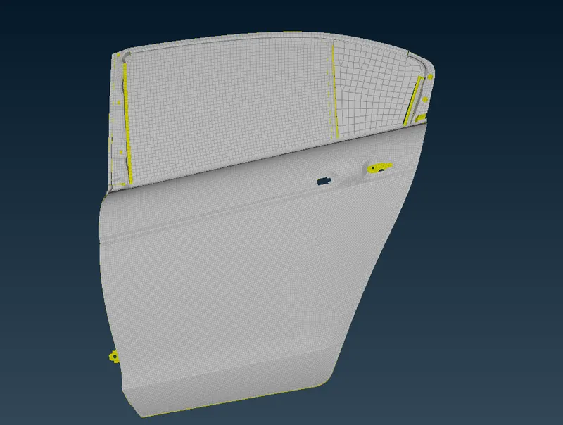
Given model;
RBE2;
- In order to connect these joints we have go to the Nastern Deck.
- nastern deck>Elements>Rbe2 elements > many node selection or two node selection according to the connection purpose.
- Generally in any rigid bodies there are two types of nodes will be available.
- slave nodes (Which are Dependent nodes) and master nodes(which are independent nodes).
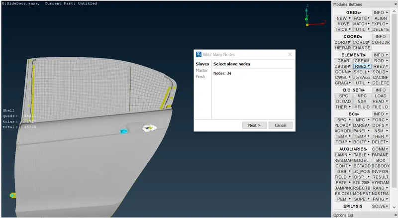
Many Node Rbe2;
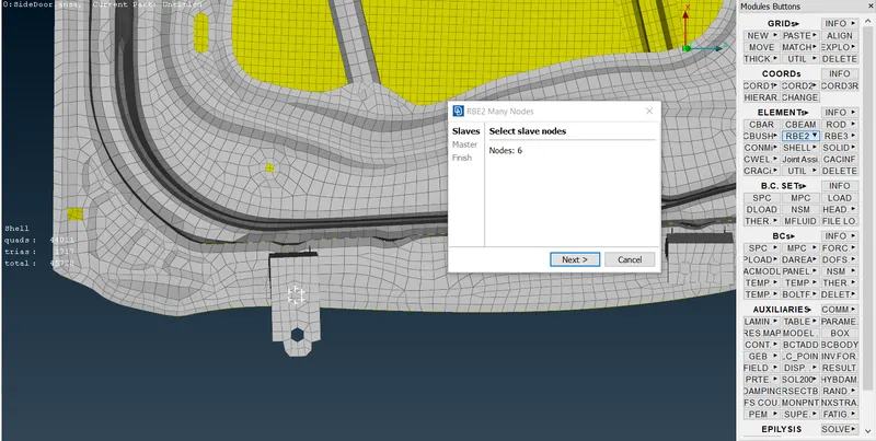
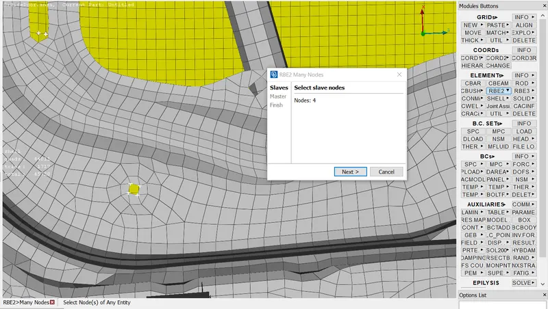
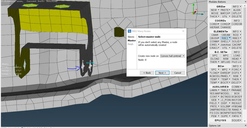
- These node selection will having different options such as feature,loop, path ,nodes will help for for an selecting a perimeters of the connection part.
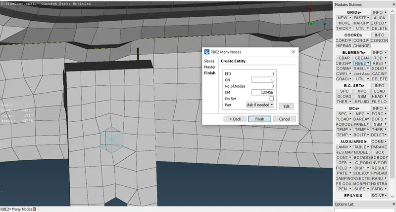
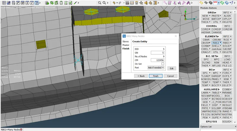
- After selecting node it will form a master and slave nodes to the connection part and next it will shows the node id, no.of nodes, and degrees of freedom of the rbe2 elements. whch shows in the below figures.
CLUSTER RBE2;
- Cluster rbe2 will be similar to the bolt connection and formed by using the Rbe2 elements, it will form a cluster representation in between two holes. This type of connection is given between the two or more holes and is deployed using the same rbe2 command.
- This type of connection is deployed in places where there is a movement involved and the Rbe2 connection will represent in where there is no movement is involved.
Two node rbe2;
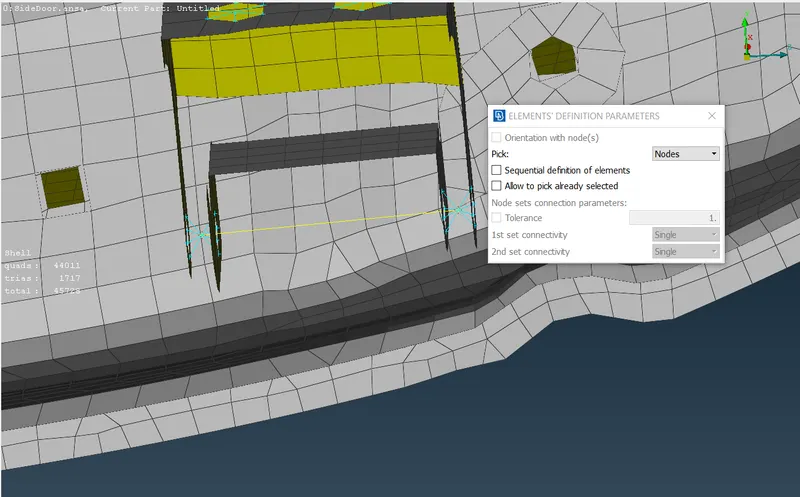
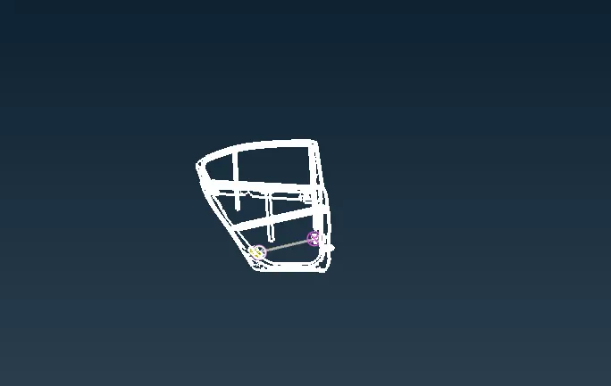
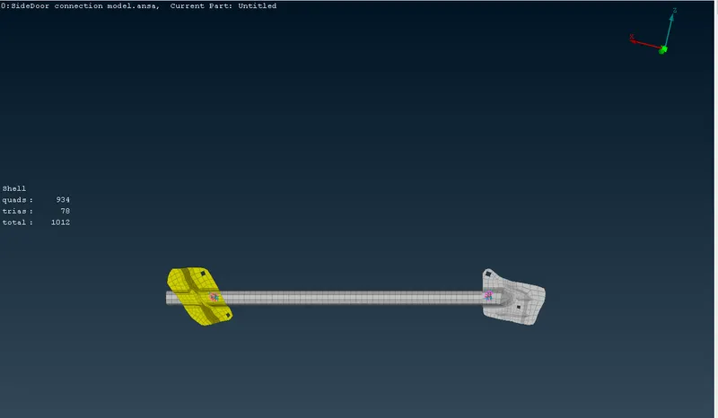
- This type of connection is given between two Master nodes of a RBE2 and It is also called as the stem representation as the connection once deployed looks like the stem of a bolt with the two sides of the connection rigid resembling a nut & a bolt. This connection is available as an option under the RBE2 command. In the options select as the Two nodes.
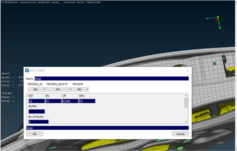
- The rbe2 will represent the each and every node id's and CM denotes the Degrees of Freedom.
- Here, 123456 denotes that the movement is restricted in translational and rotational x, y and z axis.
- We releasing the Z axes for an rotational movement of the hinges.
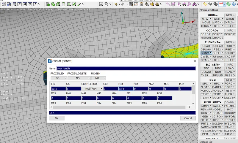
MASS;
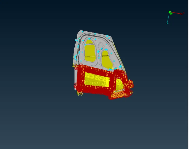
Here we are adding the mass to the master node of the door handle according to the given criteria.
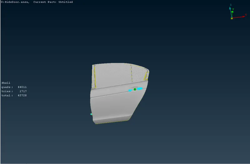
Feat2curve;
use to take an reference curve to the part by using the feature selection.
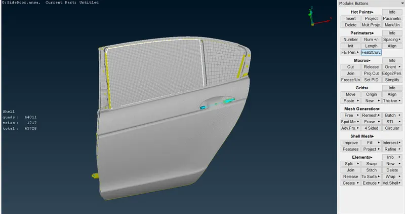
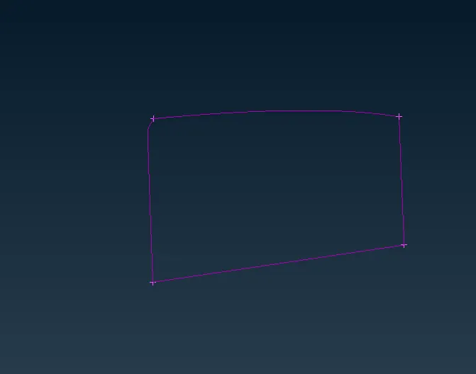
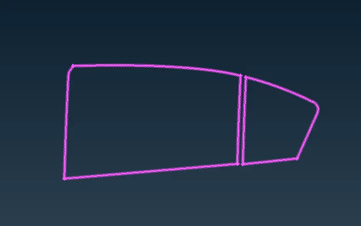
Convert> curves>select curves>convert to the spot line.
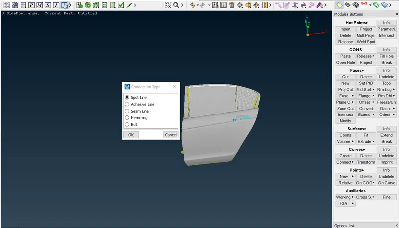
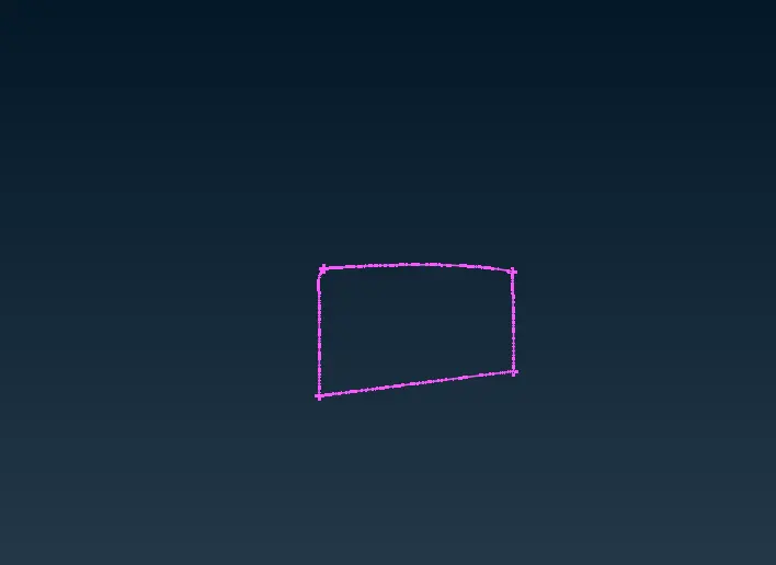
Connection Manager;
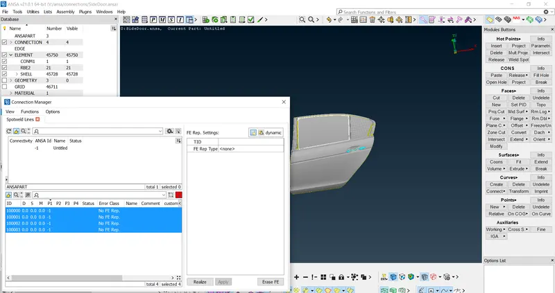
- In this connection manager we have to connect these spot line into an Rbe3CBUSHRbe3.
- First we have to select the parts(p1,p2) and next select the s ,indicate the some apporiate values.
- Set the Fe Rep type as 'Rbe3CBUSHRbe3', there it will opens the list of selection ids for the connecting parts.
- We give the search distance, rbe3 pinflages, Pbush Id where we have to create new bush property id and add the k1..to k6 stiffness values to the property card.
- Finally apply and realize the Rbe3 CBUSH Rbe3 connction to the part.
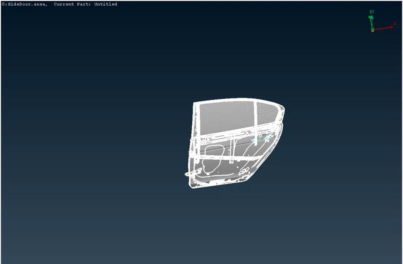

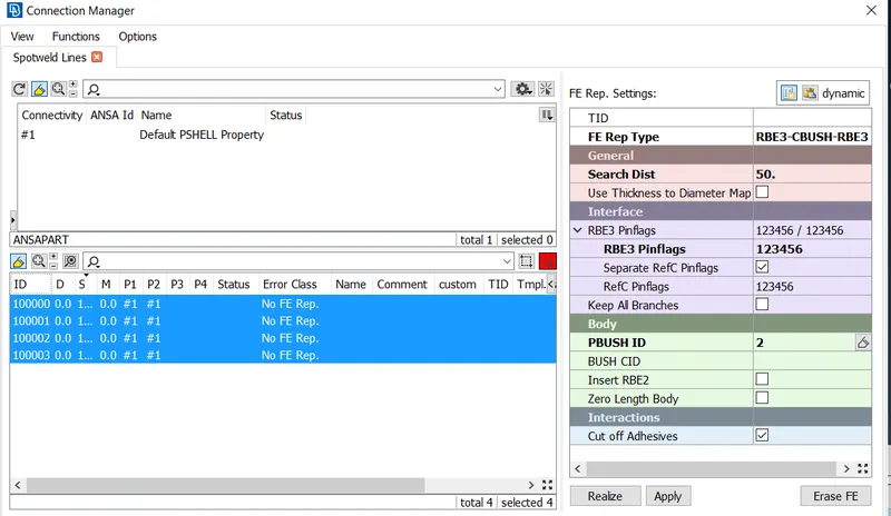
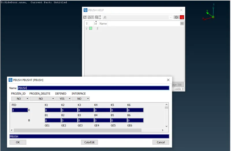
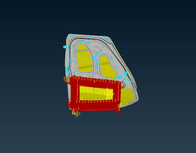
Simillarly we have done the above process to these spot line curve.
Spot Weld;
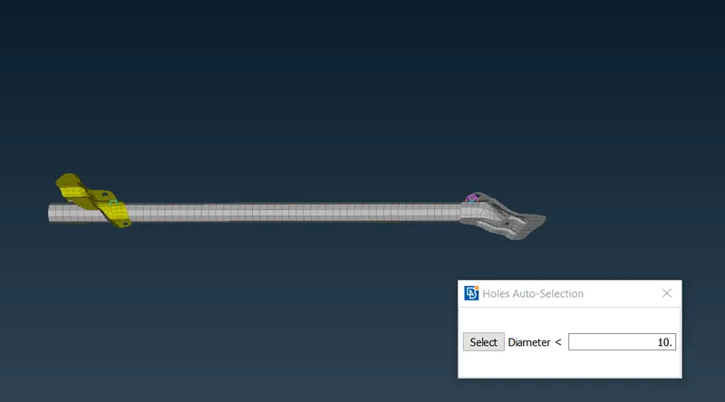
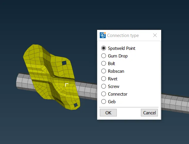
- In order to create spot weld in between two connecting parts first we should create the COG points on the connection part.
- Convert these 3D points to the spot weld point .
- Now go to the connection manager, where we set the p1 and p2 selection on the both connection part.
- Now we change the Fe Rep type as a RBE3 HEXA RBE3 form and give the search distance value .
- Then finally apply and realize the connction in between those parts.

Conclusion;
- In these section we have learnt about the deploying an connections to the different parts of an Rear door model.
- Learn about the Bolt representations, weld connections such as spot welds (C Bush connections) and rbe2 elements.
- Mass addition to the particular properties.
Here below I'M Attaching the model Link;
https://drive.google.com/file/d/1n30KCHsBsyNRKOg2ArxVa1nilCGryR_j/view?usp=sharing