Week 4- Creating the 1D elements to the Parallel Bracket model.
AIM;
To create the 1D elements on the following component with the given cross-section and degree of freedom.
MAIN OBJECTIVE;
- Creating the 1D elements to the parallel bracket model.
- Draw the middle surfaces to the given component and create material and properties to both parallel brackets.
- Make rigid elements on the brackets with the reference nodes and give cross-section according to the properties with the degrees of freedom in either translational or rotational format.
- Also, add the mass and springs to the brackets.
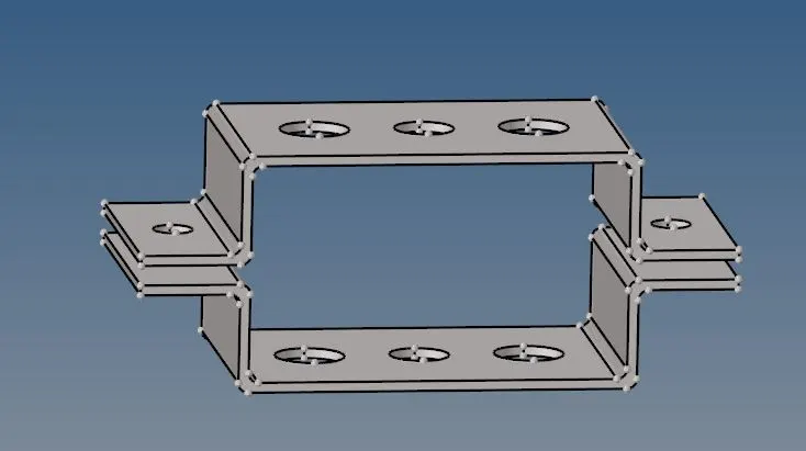
First, we import the parallel bracket from the geometry files in an iges format and import it to the GUI space area which was seen in the below figure.
MIDSURFACE;
The mid surface is basically used to decrease the number of nodes and elements in a 3D model meshing in which turns to increase the storage space and process power to needed for the entire component.
It is used to represent the entire 3D model by these surfaces and create shell elements. And these shell elements are the 2D representation of the 3D elements.

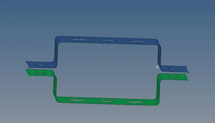
Go to the geometry, and in this were we select the Auto extraction for a given model and select the particular component in order to extract the mid surface.
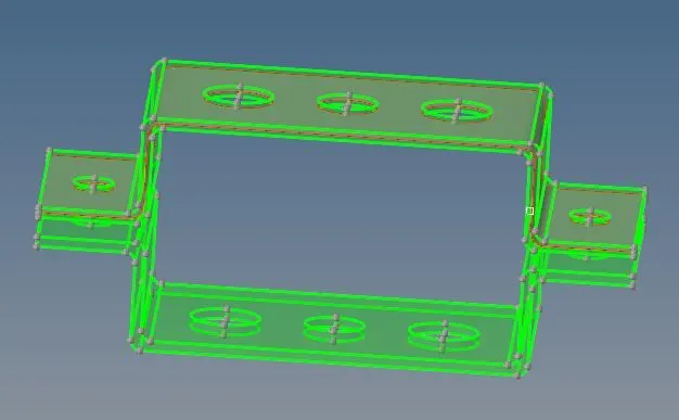
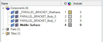
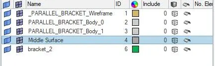
Rename the middle surface as bracket _1 and also create the new component as bracket _2. Now we extract the mid surface to the bracket_2, add the color to the component.
After this select delete  the solids of the component and delete the entire solid part as shown in the figure.
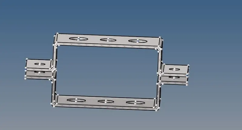
After this, we delete the parallel_bracket-body1 and 2.

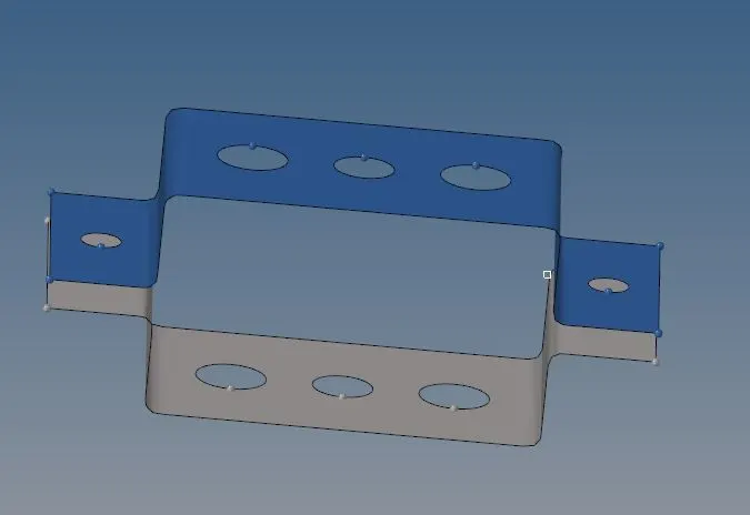
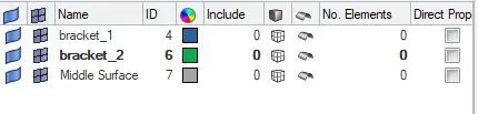
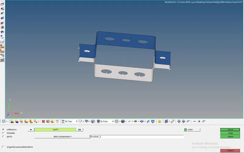
Now we see how to move the middle surface to the bracket_2, for this, we go to tool and there we organize the selected surfaces and move to the bracket_2 which is shown in below.
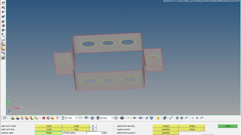
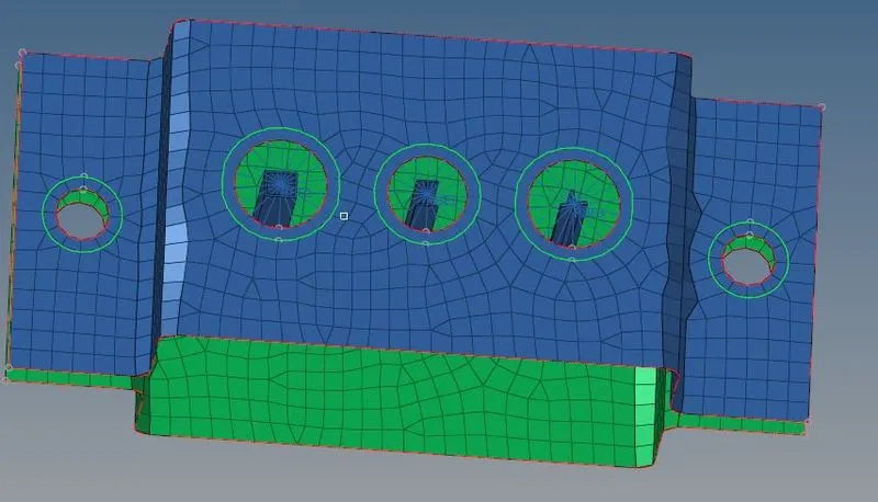
Washer split; it is used to create a washer seated on a hole in a model. First, an offset has to be specified as 5mm to determine the width of the washer and select the line to add the washers of that thickness.

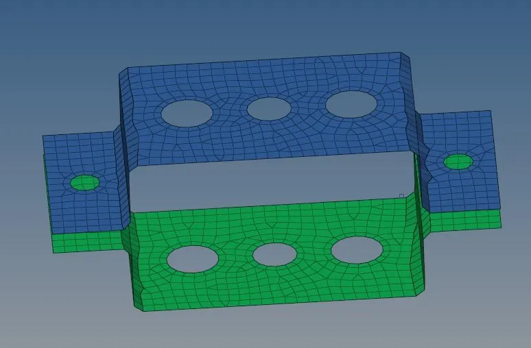
In this, we go to the 2D and auto mesh all displayed components by setting a mixed mesh type and create the mesh on them.

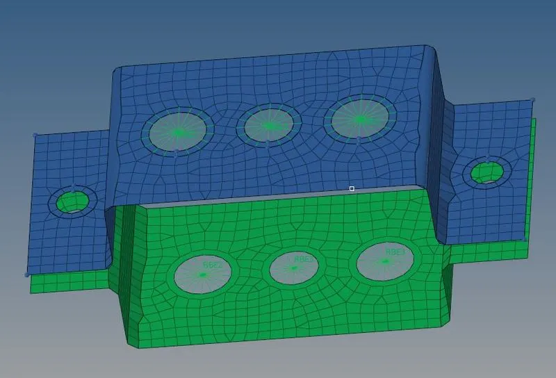
Creating the rbe2 and rbe3 elements on the parallel brackets.


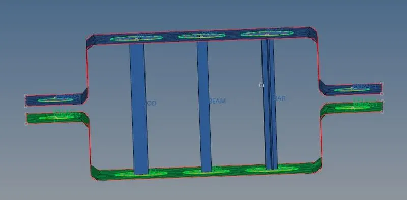
ROD; with only translational Dofs and Rbe2 link.
create>standared section>hyperbeam>Thinwalled box.
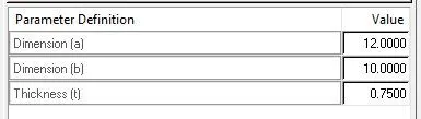
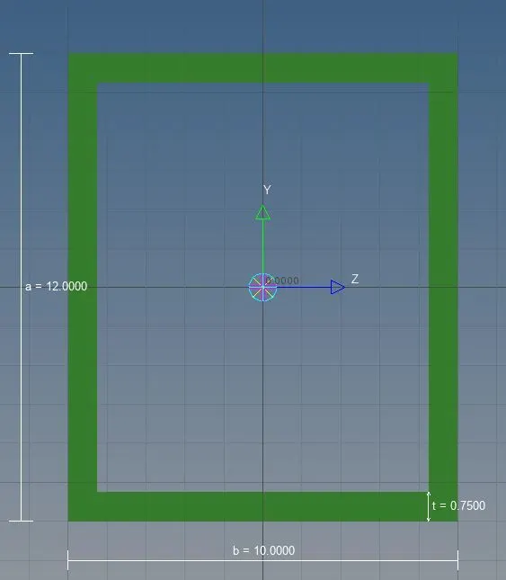
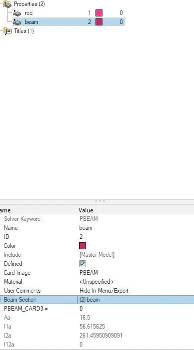
BEAM WITH I SECTION; with all Dofs and Rbe3link.
Create>standered section>hyperbeam>standared I section.
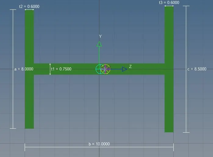
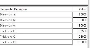
BAR; with only x and y Dofs with Rbe3 link.
Create>standared section>optisruct>Cross.
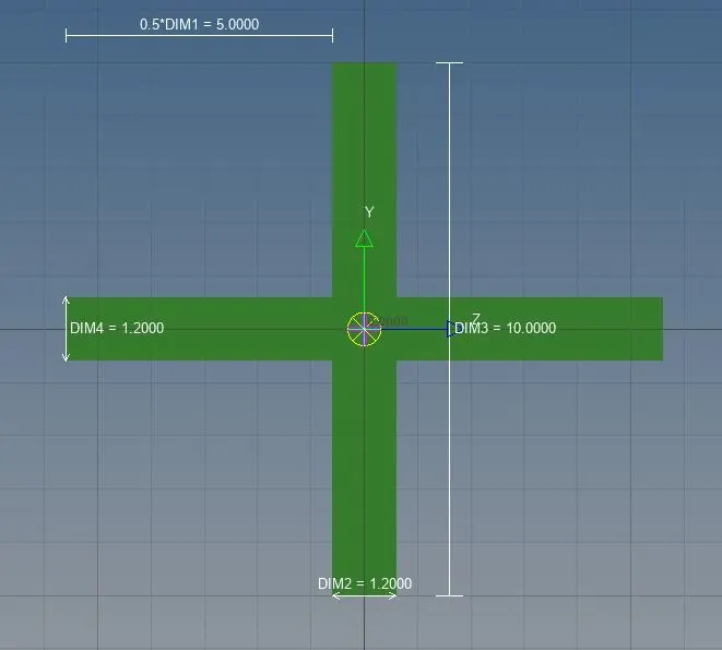
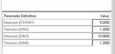
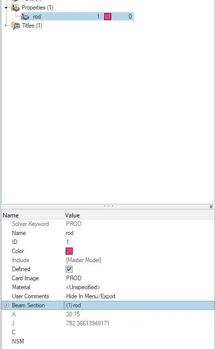
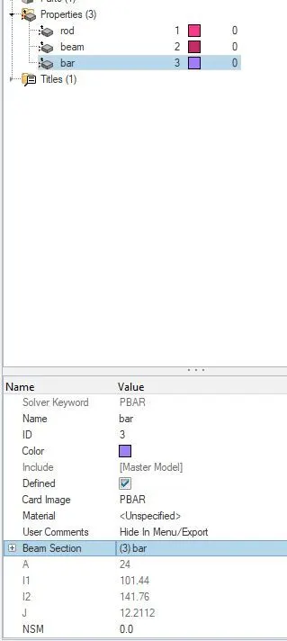
Create rod>select node 1 and node 2 and update the rod and element type crod.

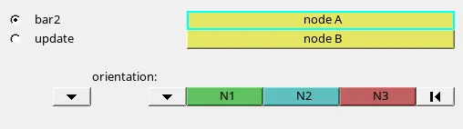
Go to 1D >Bars
In this, we create the Beam by selecting the nodes with the orientation reference points and update them. similarly, apply to the Bars as CBAR.


Go to 1D detailed representation element and view it as a 3D model of the rod, beam, and bars.
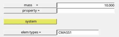
Finally, create the mass with 10mm on both brackets and attach the springs to the body components.

CONCLUSION;
We defined how to create mid surfaces and 1D elements of the parallel brackets of the model with the given rigids, dimensions, along with the Degree of freedom.