Week 6 - Creating connection for Rear door
WEEK 6 CHALLENGE
AIM
To deploy connections on the given FE model for NVH Simulation according to Nastran Deck.
PROCEDURE
- Since we are given the FE model, we deploy independent PIDS to each Pid region.
- First, we start with the door hinge, we deploy Rbe2 many node connections for rigidity on the hinge and then connect the 2 master nodes with a Rbe2 2 node connection as shown in figure 1 and figure 2.
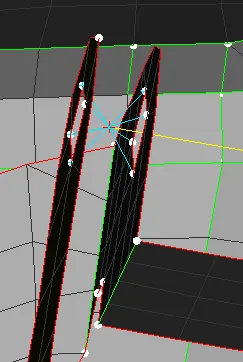
Figure 1
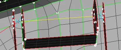
Figure2
- We then change the degrees of freedom using the info command to enable movement across one axis ( for movement of the door) as shown in figure 3.
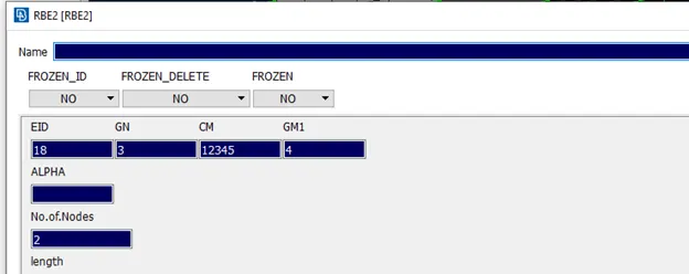
Figure3
- For regions that are connected we use cluster Rbe2 connection to show the connection as shown in figure 4 and figure 5
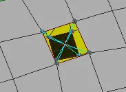
Figure 4
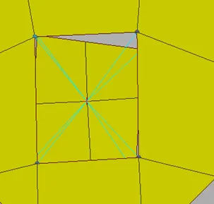
Figure 5
- Now we move on to the door handle for which we use Rbe2 many node connections and connect the master nodes with Rbe2 many node elements.
The resulting master node will denote the CoG of the component at which we set a mass of 100g using the Conm2 command as shown in figure 6 and figure 7.
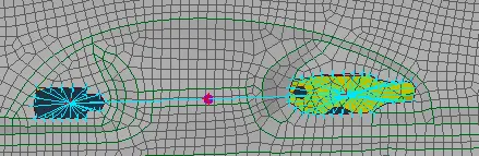
Figure 6
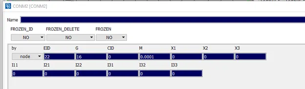
Figure 7
- Certain parts of the Fe are connected by spot welds, so we create them using the connection manager for these connections.
- First, we create a point on the part using the on cog command in the topo module, we convert this point to a spot weld using the convert option.
- Now we select connection manager, select the point, and then middle-click to go to the connection selection assistant, we choose spot weld, and then middle-click again to go to the connection manager as shown in figure 8
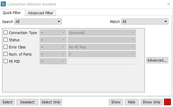
Figure8
- In the connection manager, we select p1, click f1 and then select one component and middle click. For p2 we repeat the process but select the other component. The number is shown in p1 and p2 display the PID of each component.
- Now in settings, we choose Rbe3-Hexa-Rbe3 and fill the details as shown, click apply and realize to generate the spot weld connection as shown in figure 9 and figure 10.
- This process is repeated for any other spot weld connection.
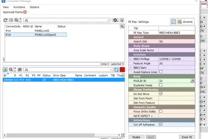
Figure 9
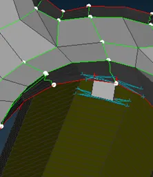
Figure 10
- Next, we move on to bolt connection. A point in the middle layer is generated using a cog, which is then converted into a bolt point using the convert option.
- Using connection manager we select the point, choose bolt in connection assistant and then fill the details as shown.P1, P2 and P3 are the 3 layers on which the bolt is connected.
- Click apply and realize to generate the connection.
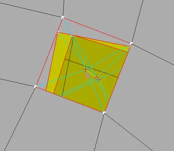
Figure 11
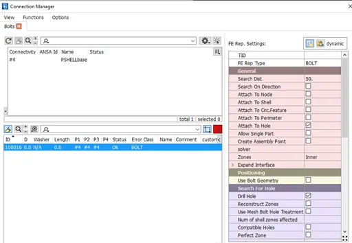
Figure 12
- For the weather strip, we denote the connection using bush elements.
- First we generate a curve using feat2curve option in mesh module, these curves are then transformed to the middle using transform option and then converted to spotlines.
- The spotlines are selected under connection manager, with spotline connection as the type under the assistant.
- The details are filled as shown under Rbe3-Cbush-Rbe3, S is the distance between each Bush element and p1 and p2 are the window and frame respectively.
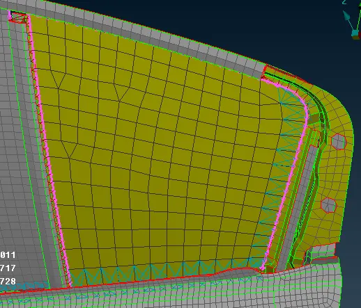
Figure 13
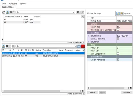
Figure14
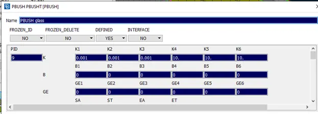
Figure 15
Learning Outcomes
The following skills were learned and practiced during this challenge.
- Connections using Nastran Deck
- Automatic Connections using connection manager
- Rbe2,Conmi,Cbush,bolt,spot weld,Spot Line connections were practiced
- Editing Degrees of Freedom of deployed connection
Conclusion
The connections for the given Fe model were successfully added and verified for NVH testing.