Week 6 - Creating connection for Rear door
AIM:
To create and apply different PID’s and deploy FE connections to the given rear door FE model.
PROCEDURE:
- Import the given FE rear door model
- Create PID’s for each parts seperately
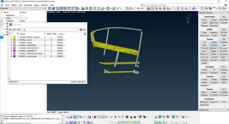
- For BOLT connections
a)Create 3D point
b)For creating a 3D point ,first create a centrepoint
c)Go to TOPO module>POINTS>ONCOG
d)Use LOOP selection tool and select the edge
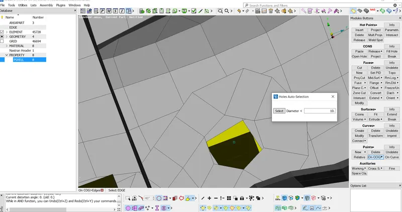
e)Convert the 3D point to a bolt
f)Go to CONNECTIONS>3DPOINT>BOLTS
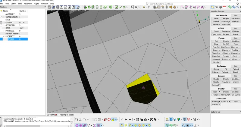
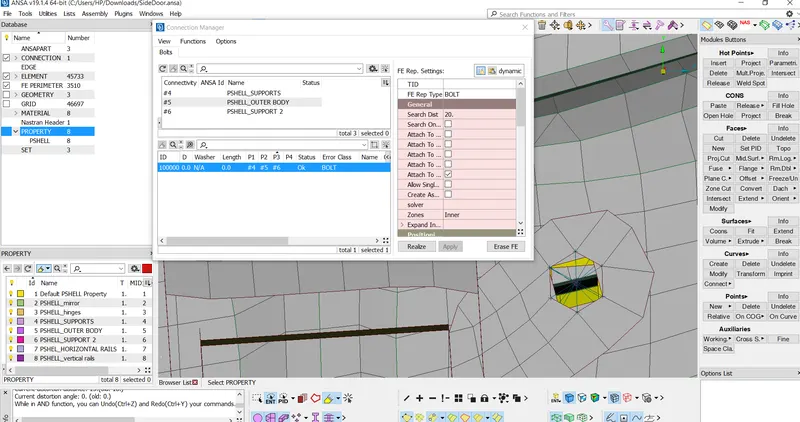
g)Go to Connection manager and create PID's(P1,P2,P3)
h)Give FE representation as BOLT
i)Give search distance
j)Apply and realize
2.BOLT Connection (MANUAL):
- Go to NASTRAN deck >ELEMENTS>RBE2>Many nodes
- Select the edge using LOOP selection
- Similarly select the other edge using same process
- Finally the Cluster RBE2 are formed by two Master nodes
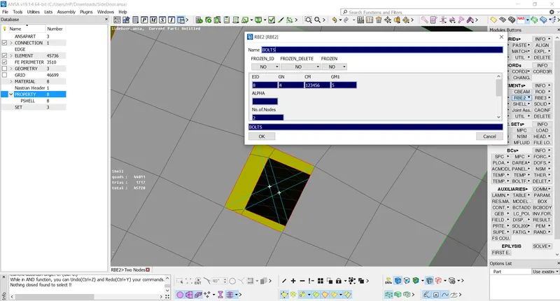
- Similalry Find and Connect all Bolt areas
2.For HINGES:
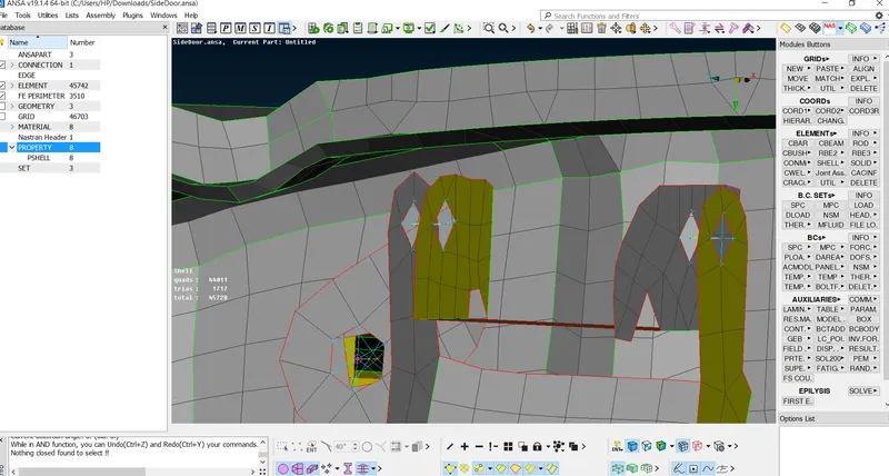
- Go to NASTRAN deck >ELEMENTS>RBE2>Many nodes
- Create Cluster RBE2 as shown below
- Go to NASTRAN deck >ELEMENTS>RBE2>TWOnodes
- Select the two master nodes
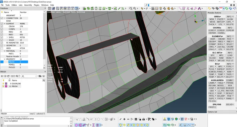
- In this case ,Go to CM and remove One Rotational DOF(Remove 6th,)
- Here in CM-123456,123-Translational XYZ and 456-rotational XYZ
- TWO nodes RBE2-Represents the stem of the BOLT
- Many node RBE2-Represent the rigid connections
2.For Door handle:
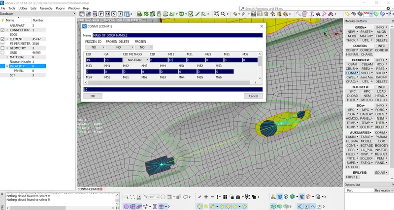
- Rigidize the holes by giving a rigid connection
- For Door Handle ,we have to define mass element
- For defining mass elements Goto NASTRANDECK>E;EMENTS>CONMI>CONM2>NODES
- Define the mass ,Apply 0.001 tonnes as mass
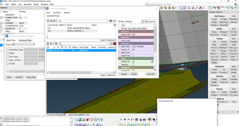
3.For SPOT welds:
a)Create 3D point
b)For creating a 3D point ,first create a centrepoint
c)Go to TOPO module>POINTS>ONCOG
d)Use Entity selection tool and select the edges
e)Convert the 3D point to a spot weld point
f)Go to CONNECTIONS>3DPOINT>BOLTS
g)Go to Connection manager and create PID's(P1,P2,P3)
h)Give FE representation as RBE3-HEXA-RBE3
i)Give search distance
j)Create WELD PID
j)Apply and realize
4.For CBUSH Connection:
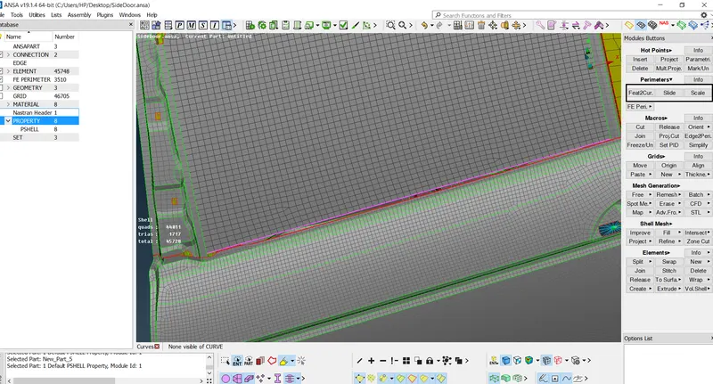
- Create a curve
- Goto MEsh module>curves>feature2curve
- convert the CURVE to spotline
-
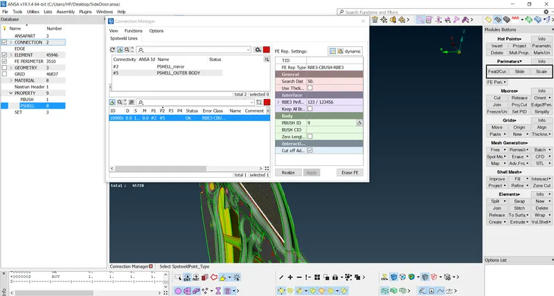
- Go to Connection manager and create PID's(P1,P2,P3)
- Give FE representation as RBE3-CBUSH-RBE3
- Give search distance
- Create bush PID
- Apply and realize
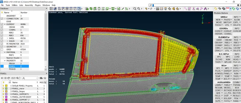
- Select the other dpotline on the other sides of mirror and follow the same process
- Final representation of Cbush as below
Conclusion:
Different types of connections used in the rear door of the car is provided and the way it should be represented in FE has also been given.These are the Connections performed in this model:
1)TWO NODES RBE2:Represents the stem of the bolts
2)MANY NODE RBE2:Represents the Rigid connections
3)FE Representation-
- For BOLTS - BOLTS
- For Spot WELD - RBE3-HEXA-RBE3
- For CBUSH connections - RBE3-CBUSH-RBE3
- For Door Handle -CONMi