Week 6 - Creating connection for Rear door
AIM: To make proper connections between components using Nastran deck for NVH Analysis.
Procedure:
- Import FE model.
- Set different components in different PIDs.
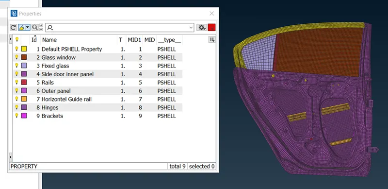
- Start by displaying the components which are to be connected.
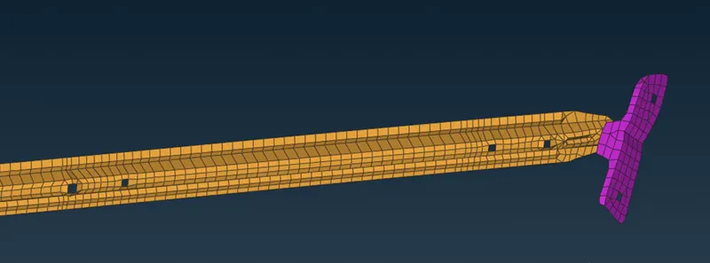
Connection type: Spot weld with RBE3 elements.
Reason: here the horizontal component should be attched to the bracket with the help of spot weld that’s because the is fixed with the horizontal component or the bracket does not move and if you want to connect it with seam weld, that would require more spaceand as you ca see in image is less space to perform seam weld, so spot weld is the best option.
How to:-
- First create a 3D point on bracket and horizonatl componet.
-Go to Topo module—Points—On COG.
-Select the element edges as shown in image and click middle mouse button.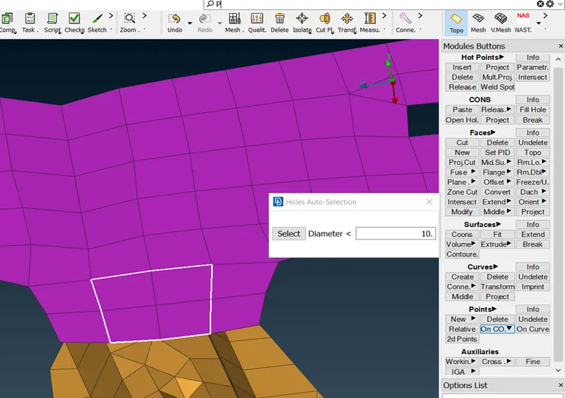
2.Convert this 3D point to connection entity.
- Go to Convert option in Assembly toolbar—select 3D point.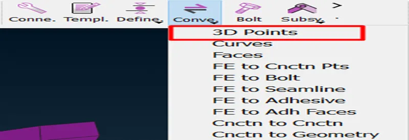
- Select spot weld from the dialouge box which pops up after selecting 3D points.
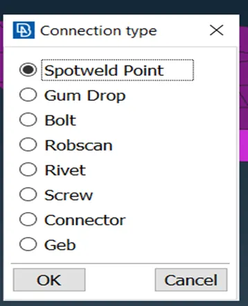
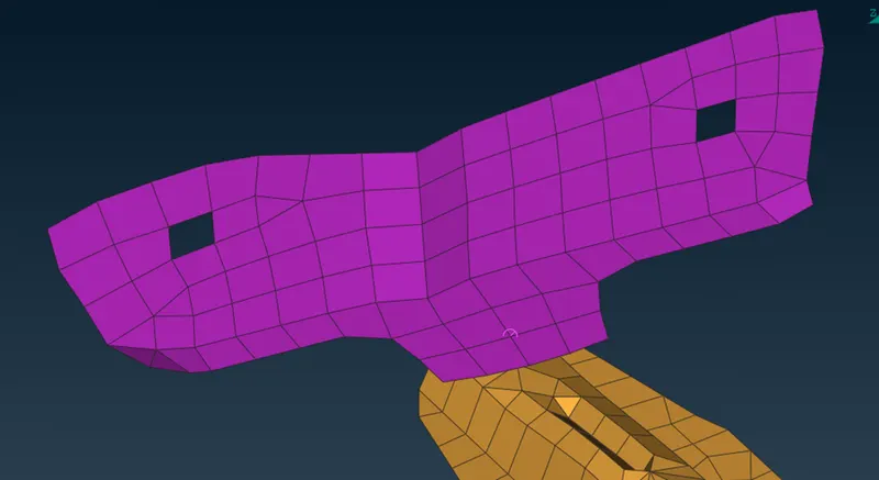
3. Go to connection manager, select the displayed spot weld connection entities and click M.M.B.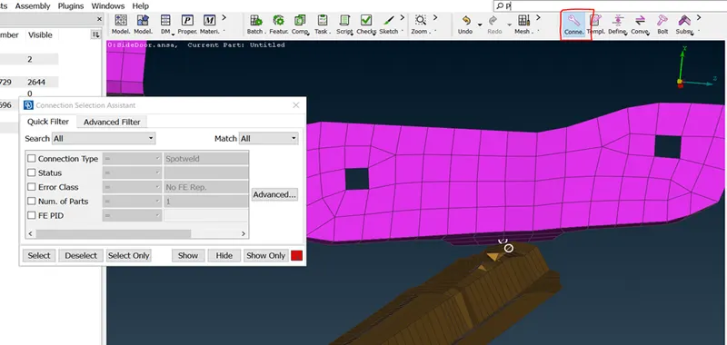
This dialouge box pops up, first assign part 1 and part 2
-right click on P1 or P2 then press F1, it will ask you to select the component which you want to assign as part1 or part2, then M.M.B.
-Now, select FE Rep Type as RBE3-HEXA-RBE3 that the element type for spot weld.
- Set Search distance as 10 (this is user’s call, as the user has to specify the approx. dist. Between two components.)
-Set RBE3 pinflags as 123456 because all the dof of the element should be constained as the component is rigid which means it shouldn’t move or rotate in any direction.
-and lastly set solid id for the spot weld.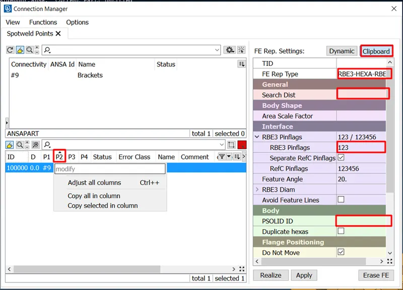
-it will look like this.
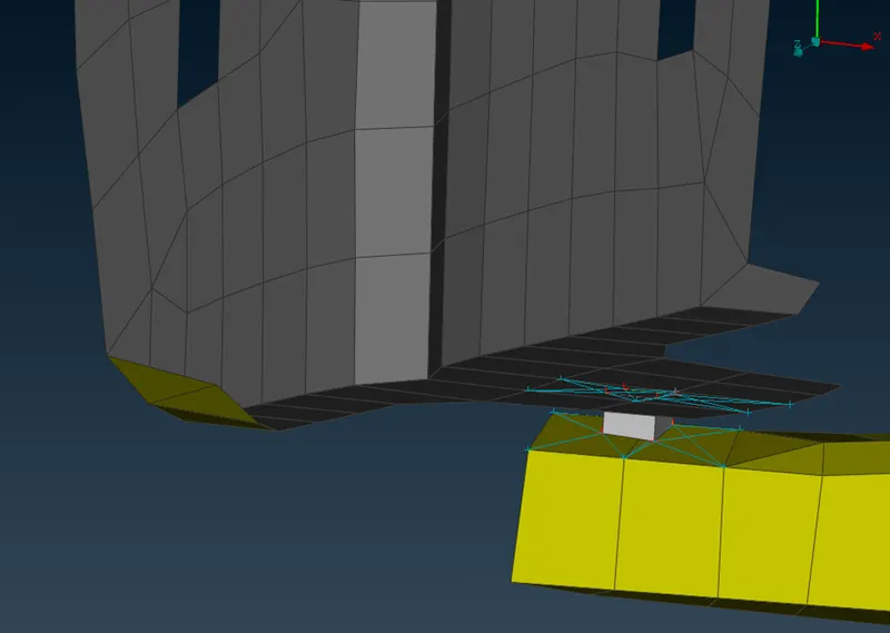
- Connection type: Seam weld for below shown components.
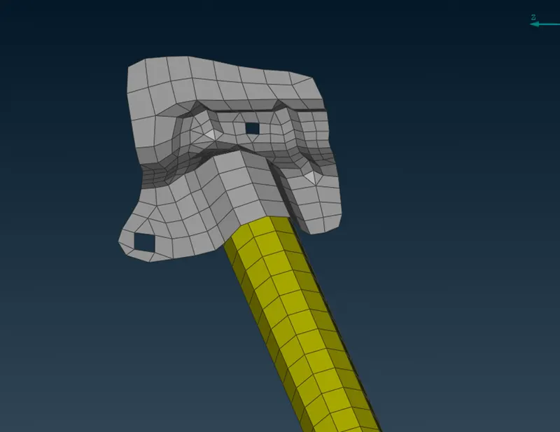
Reason: At this place Seam weld with overlap shell elements, will be appropriate because the components should not move w.r.t each other, if spot weld is applied, there are chances of movement between both components.
How to:
- The procedure is same as explained in spot weld, but this time curves are used instead of 3D point.
-Use Cons2Curves from Topo module- curves.
-select the element’s edges as shown in image and click M.M.B.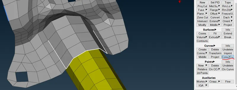
2. Go to covert option, select curves from it.
-select the displayed line/curves and press M.M.B.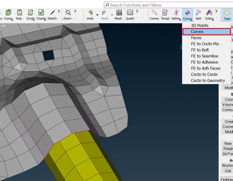
-this will pop up.
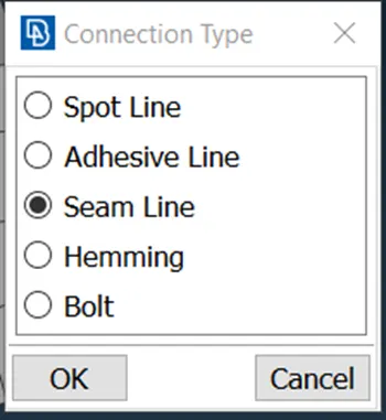
-select Seam line. And click ok.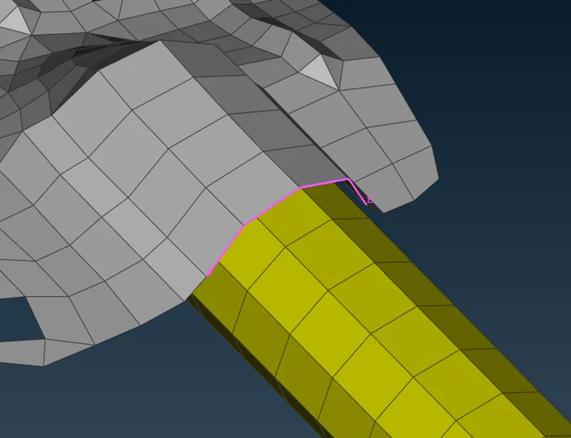
-Go to Connection manager, select the converted curve and press M.M.B.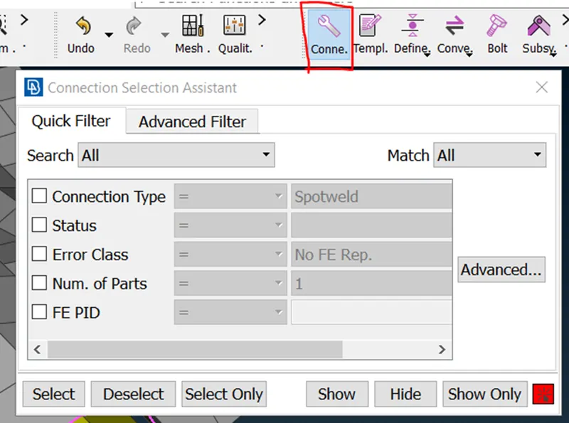
-this dialouge box will pop up.
-set the values as shown in image, click apply and realize.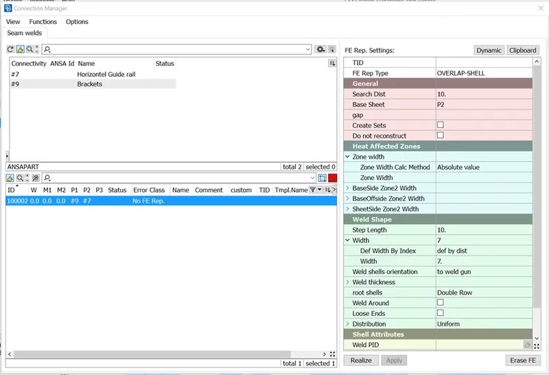
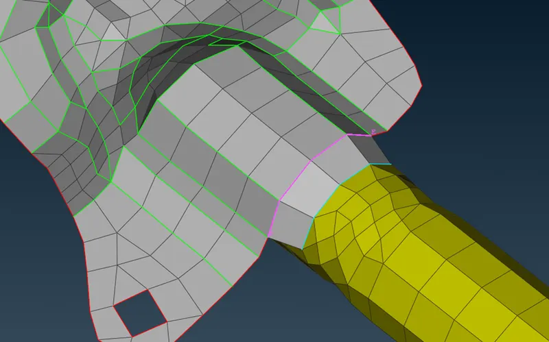
- Connection Type: seam weld
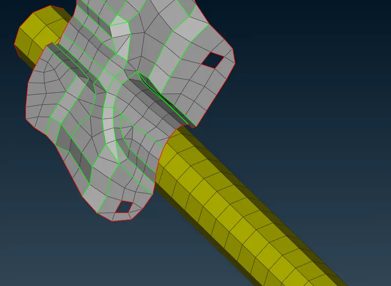
Reason: Same as mentioned in previous connection.
How to: Same as mentioned in previous connection.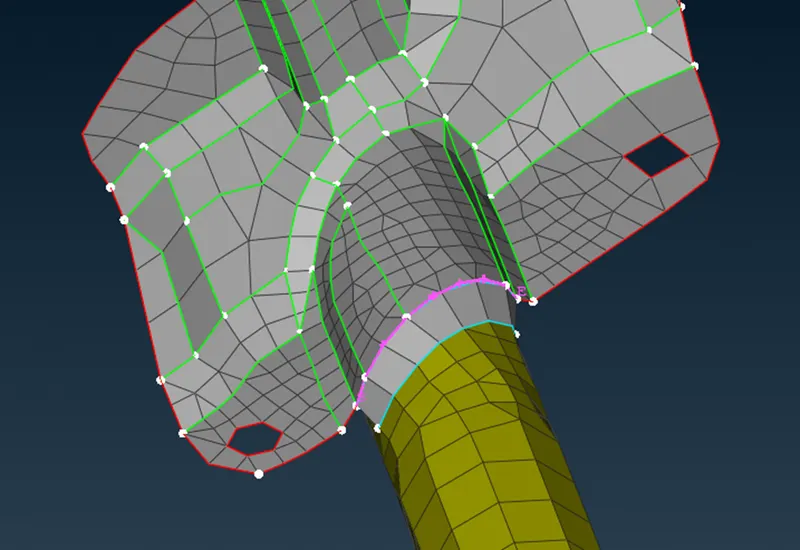
- Connection Type: RBE3 CBUSH ELEMENTS.
Reason: At window glass line there are damping elements present, because a rubber guide is present between window glass line and the door panel, to absorb small vibration, as the door opens and closes frequently, so vibration generates and it causes damage to the components.
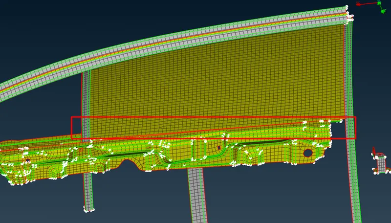
How to:
- Select the perimeter (edges) of window glass line and convert it into curves by using Feat2curves option from mesh modules-perimeters.
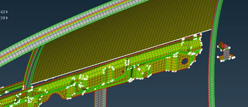
- Select spot line from convert option.
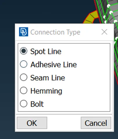
5. Set options as shown in image.
6.After realize, this is the result.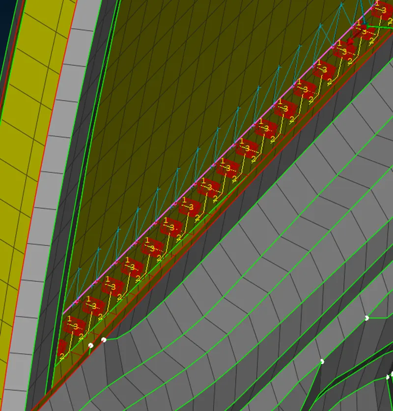
7. do the same on other side.
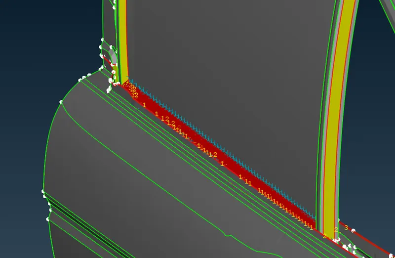
8. do the same all other side of window glass door.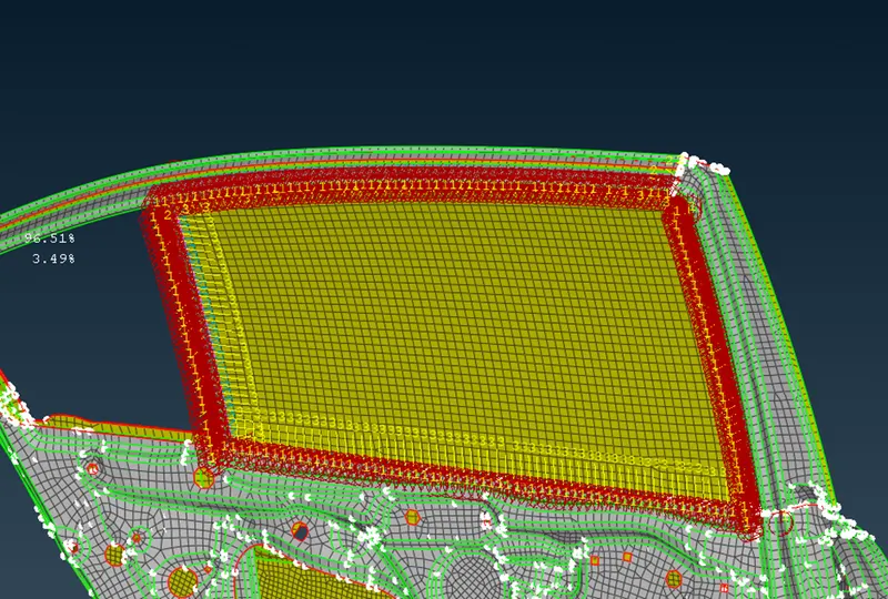
- Connection type: RBE2 elements as the door handle.
Reason: CAD model of Door handle can converted into FE model, but to decrease analysis time during a simualtion run, we can remove FE model and put RBE2 elements in a specific way and assigning a mass on it. This is represent as a handle of car door.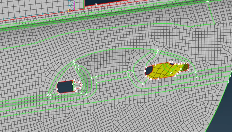
How to:
-go to nastran module and select RBE2 many nodes element from element module buttons.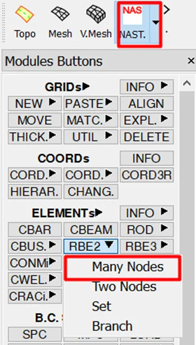
-select nodes as shown in image and press next and finish.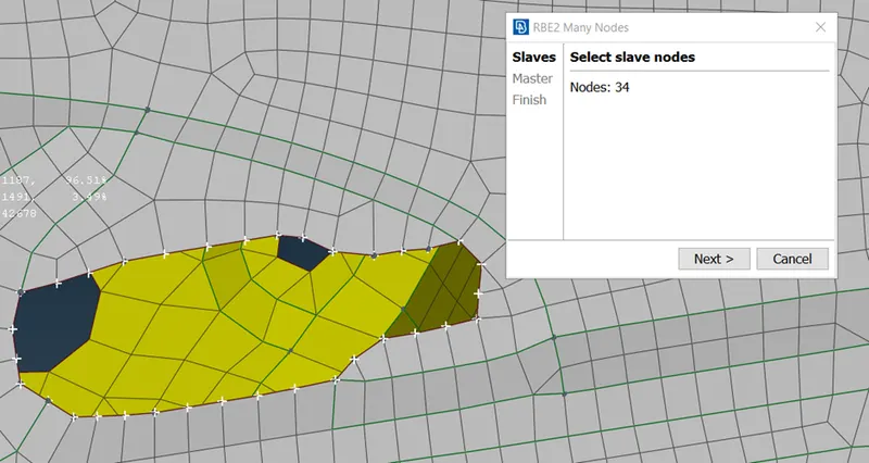
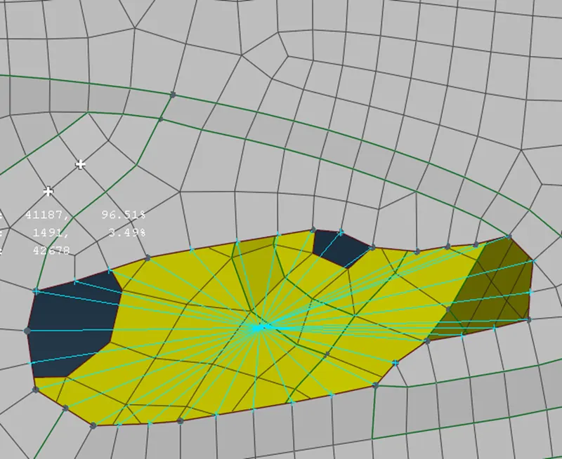
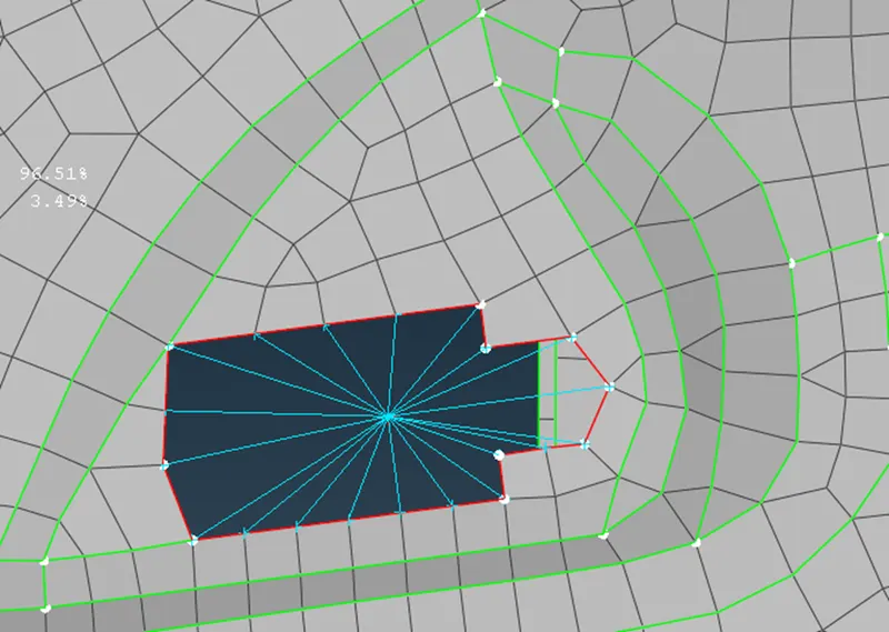
-now create a RBE2 two node element between both clustered RBE2 elements just created now.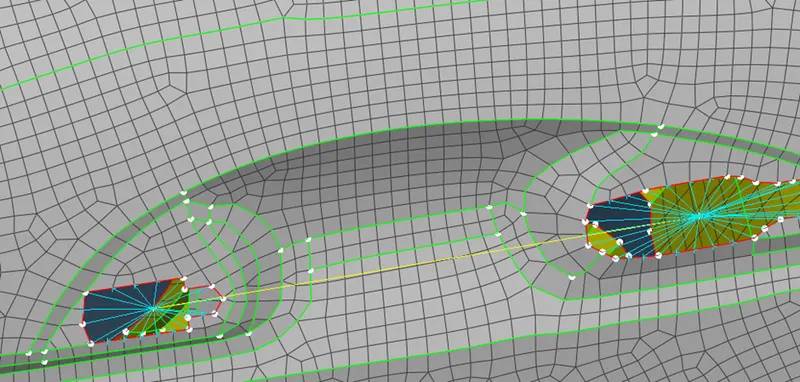
-after this assign mass to the RBE2 element on door handle.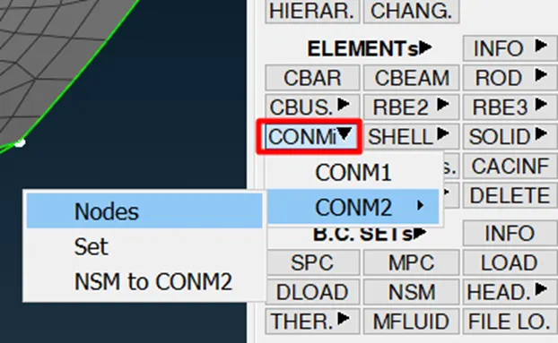
-select the node and pres M.M.B.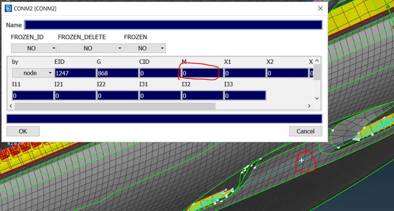
-here assign mass.
NOTE: the mass is in metric tonne.
So assuming mass of handle to be 100gms therefore M=0.0001 tonne.
Assign this value the press ok. 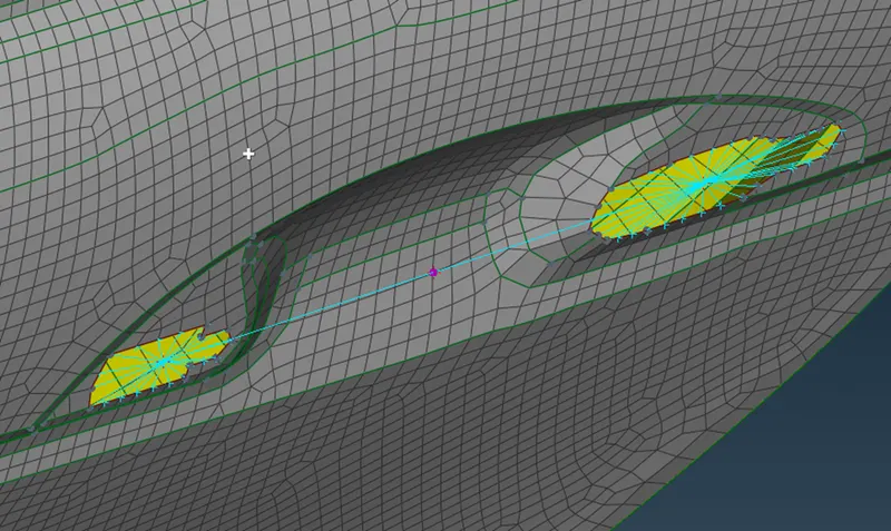
8. Connection type: RBE2 elements on fixed window.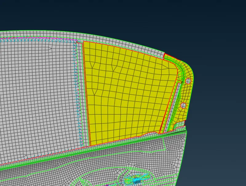
-Reason: The window is fixed, RBE2 elements will not allow any displacements.
How to:
-same as done in point
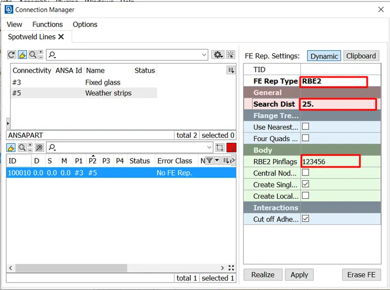
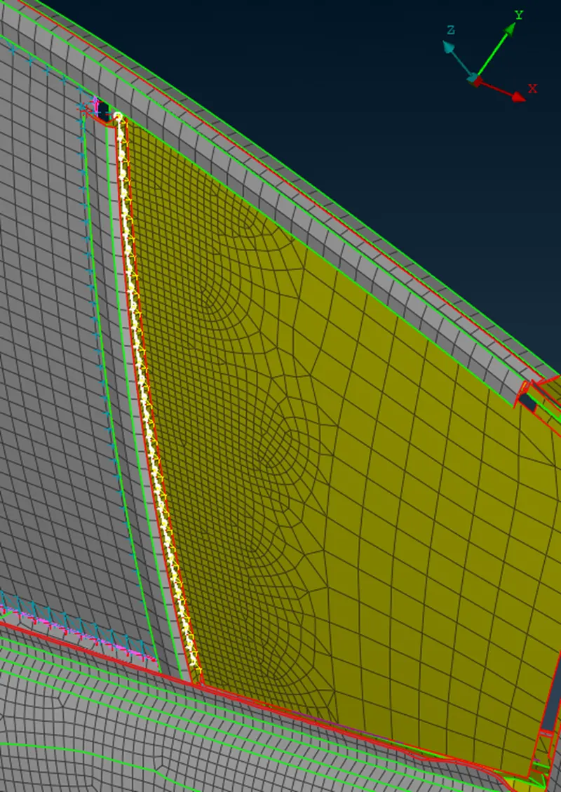
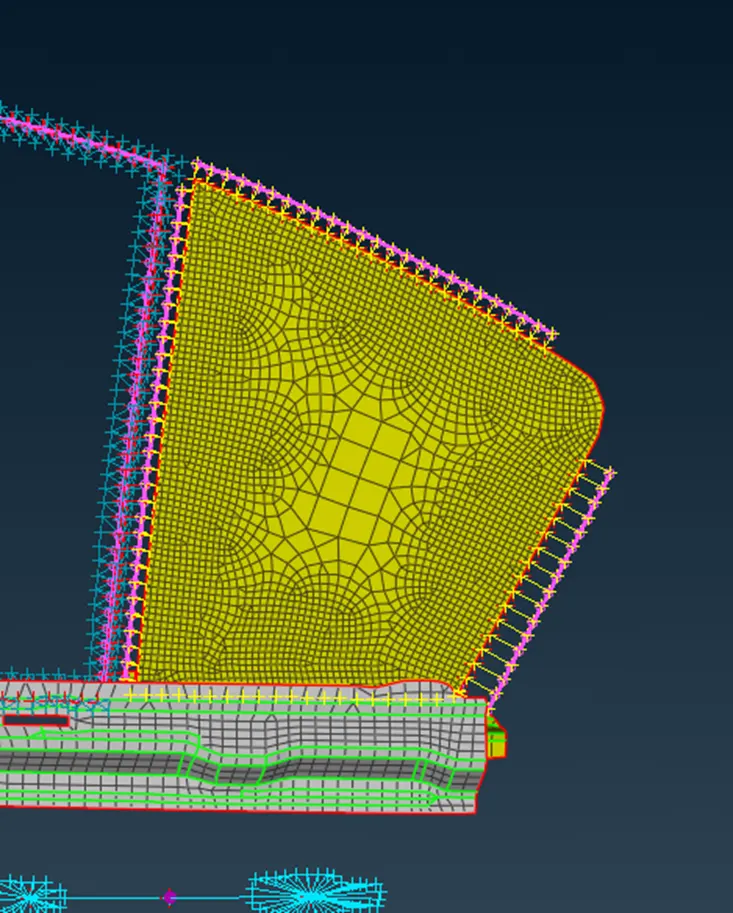
-final result.
- Connection Type: Bolts at hinge area.
How to:
-First create a 3D point at one of the hole of any component, where bolt is to be mounted.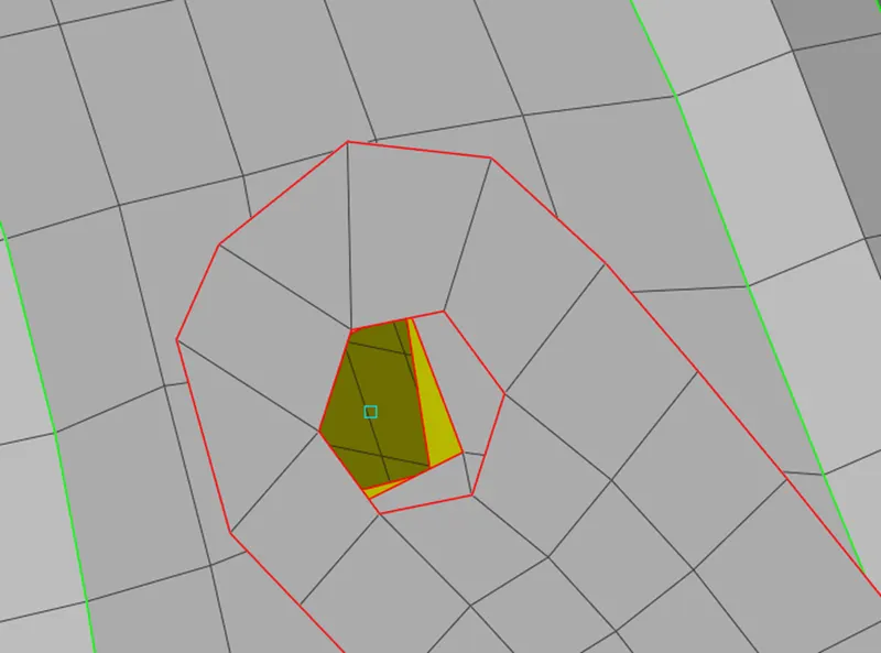
-convert this 3D point into bolt connection type.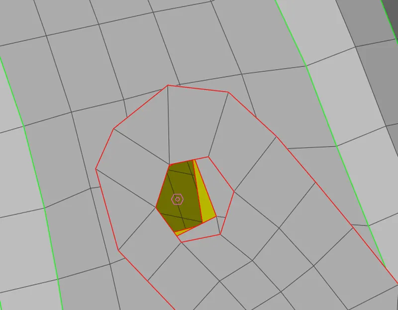
-from connection manager choose bolt.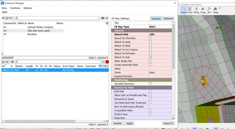
-this is the result.
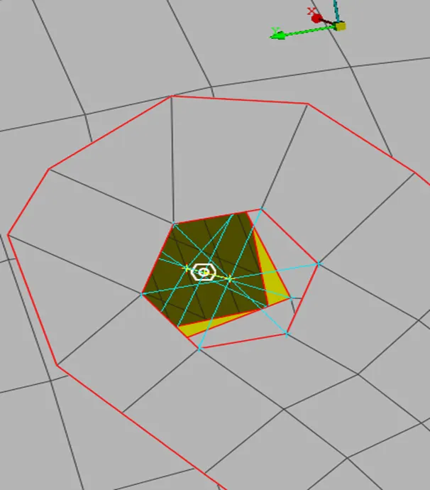
-do this connection wherever necessary.
Create RBE2 elements wherever there is a hole because the holes are given for another component to get attached or mounted on it, if you done have that component in model, then create RBE2 many nodes element at those places.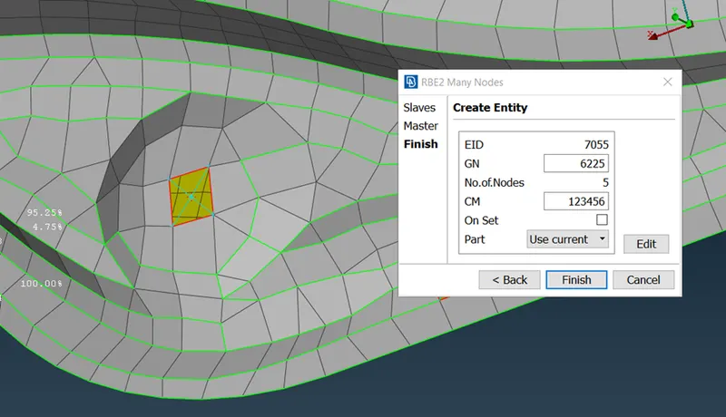
Conclusion:
- Connections should be done for specifying the Dof of components.
- Seam and spot welds are widely used in industries.
- Bolted connections are also common.
Outcome:
-These connections are done to reduce Analysis time, during simualtion run, as physical FE model will increase no. of nodes which inturn increases the Dof per node.
-These Dofs are to be solved by solvers, which takes time, this time is called computational time, which is to be decreased by CAE engineer.