Week 6 - Creating connection for Rear door
CREATING CONNECTIONS ON REAR DOOR
AIM : To create the appropriate connections between various parts of a door using ANSA in NASTRAN Deck ( preparing a part for simulation in NASTRAN TOOL).
PROCEDURE :
- Import CAD geometry.
- Differentiate the whole CAD into different components / entities as the connections require the parts to be connected in different PID's . This can be done by using the SET PID option in the TOPO Below are the images which shows the component before and after setting PID's .
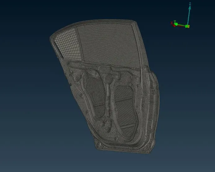
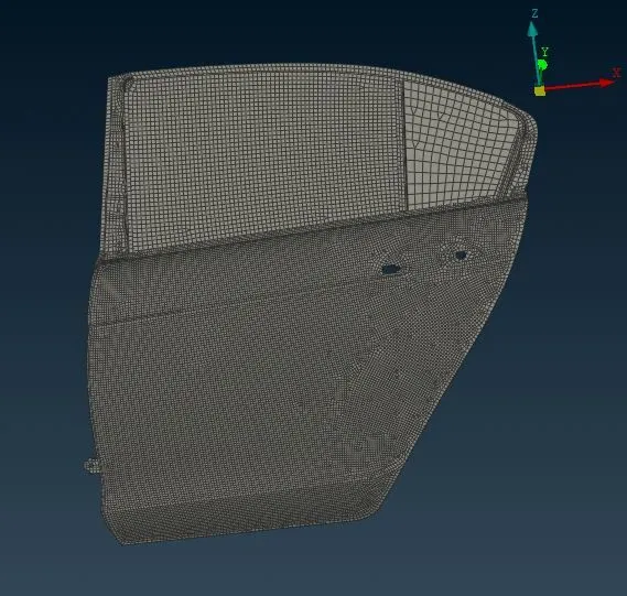
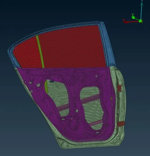
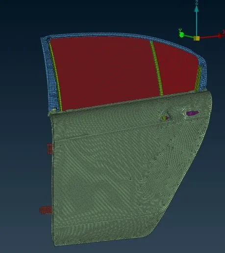
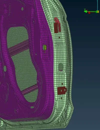
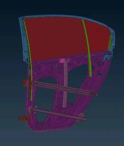
- By using RBE2 - MANY NODES from ELEMENTS - Nastran deck , Create a RBE2 connection at the hole region where there will be bolt connection .
- At the hinge portion - first create the RBE2 connection at each and , by using RBE2 - TWO NODES connect the two master nodes , and assign the degree of freedom to the hinge as the door has to rotate along Y axis for opening and closing purpose.
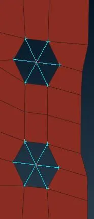
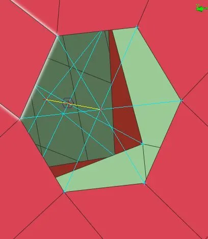
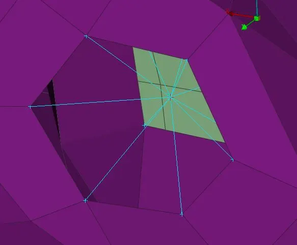
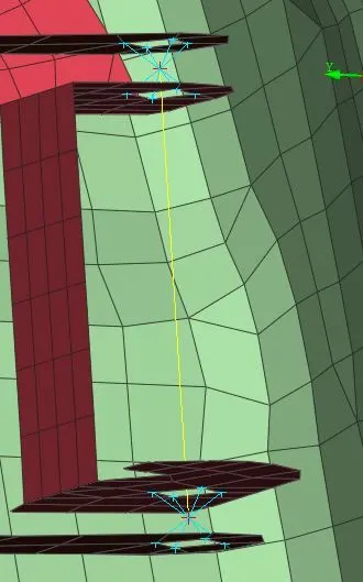
- To create the Bolt connection for multiple layers , can also be done using connection manager . For this process first create a COG point between any one of the layer , by using CONVERT - 3D POINTS - BOLT option - convert the COG point to bolt connection . Next by using connection manager and FE TYPE as BOLT - select the entities that had be connected and click on realise to create the connection.
- By creating a connection called cluster node RBE2 elements , multiple entities can be connected for bolt connection . This can be done by using RBE2 - MANY NODES and selecting those multiple layers . In this type of connection there will be only single master node for all the entities.
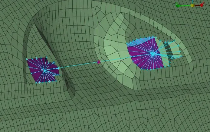
- To create the connection for door handle , create RBE2 - MANY NODES connection at two different handle holes and then connect both the master nodes of 2 holes by RBE2 - TWO NODES . Then assign a mass that represent the handle for simulation using ELEMENTS - CONMi - CONMi2 in NASTRAN module and assign the mass of the handle.
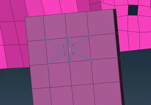
- To create a connection that represent the spot welding , create a COG point at the place , by using CONVERT - 3D POINTS - SPOT WELD convert the 3D point to spot weld point . Next by using connection manager select the entities that has to be connected and FE type as RBE3 - HEXA - RBE3 and realise to create the spot weld connection.
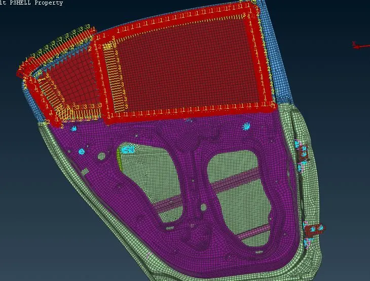
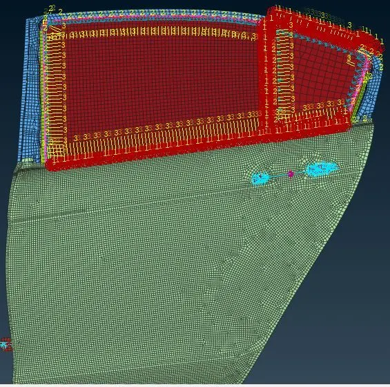
- The glass region has to be modelled as a rigid body but having the damping co-efficients as the glass / mirror is surrounded by the rubber element called as weather strips .
- To connect the mirror portion first create a curve using PERIMETER - FEAT2CURVE option from shell module . These curves are then converted to spot line using CONVERT - SPOT LINE option . Each curve has to selected at once .
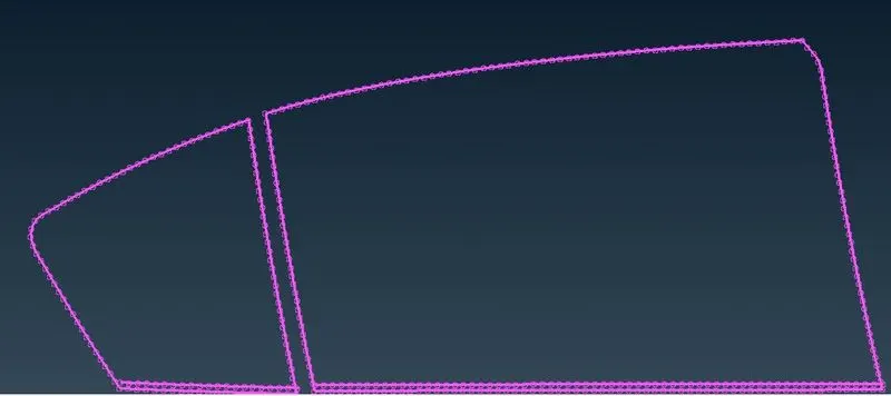
- By using connection manager and FE type as RBE3 - CBUSH - RBE3 , and select the neighbouring entity to create the connection .
- Given Stiffness values have to be updated for the CBUSH elements . Click on PBUSH ID and press ENTER + ? keys and assign the stiffness value .
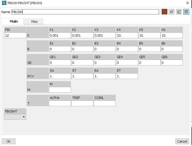
- The CBUSH elements that have been created will be having different coordinate system - need to be assigned with GCS (global coordinate system).
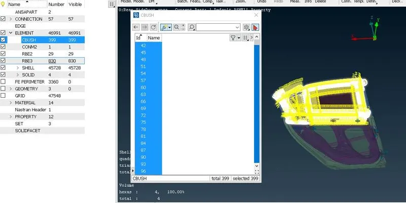
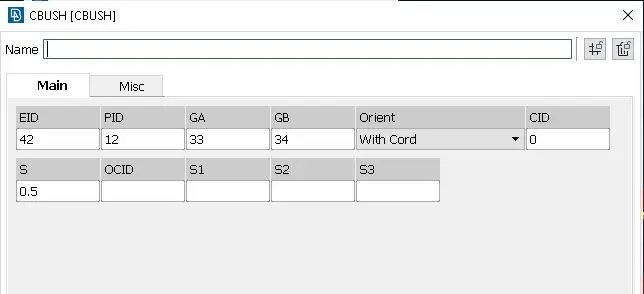
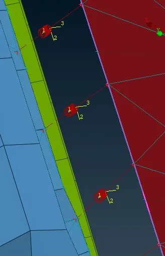
- To create this go to DASHBOARD - CBUSH ELEMENT - select all elements and give ORIENT as WITH CORD and CID value as 0 .
CONCLUSION : Suitable Connections were created on the Side Door model .
LEARNING OUTCOMES :
1) How to connect various parts with appropriate connections
2) New concept of Tailor welding .
https://drive.google.com/file/d/1A-QlyAMzRdruv78Vvjx5V0ABf_w8kIby/view?usp=share_link