Week 3 - 2D meshing for sheet metal
2D-MESHING ON A CAR HOOD USING ANSA
Aim :
To create a 2D mesh on a hood (sheet metal component) using ANSA with given quality criteria.
Objective:
1) To perform meshing on the given hood component using ANSA tool based on given quality criteria
2) Topology cleanup for the component
3) Assigning thickness and extracting Mid surface of sub-components of the hood
4) Generate mesh on the component and optimize the mesh wherever requied for obtaining better mesh flow.
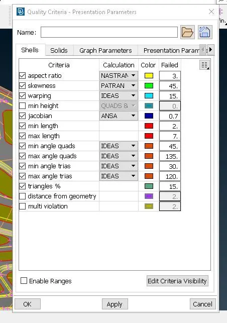
The following are the given quality criteria of the mesh that is to be generated.
|
S.N0 |
Quality criteria |
value |
|
1 |
Target / average length |
5 |
|
2 |
Minimum length |
2 |
|
3 |
Maximum length |
7 |
|
4 |
Aspect ratio |
3 |
|
5 |
Warpage |
15 |
|
6 |
Skewness |
45 |
|
7 |
Jacobian |
0.7 |
|
8 |
Minimum quad angle |
45 |
|
9 |
Maximum quad angle |
135 |
|
10 |
Minimum tria angle |
30 |
|
11 |
Maximum tria angle |
120 |
|
12 |
Tria percentage |
15 |
Procedure:
- Import the cad model which is in the stp. extension.
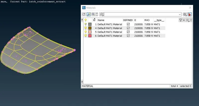
- Define the material.
- Using 'CHECK GEOMETRY' in the checks menu , execute a run which checks for any geometry error or topological error.
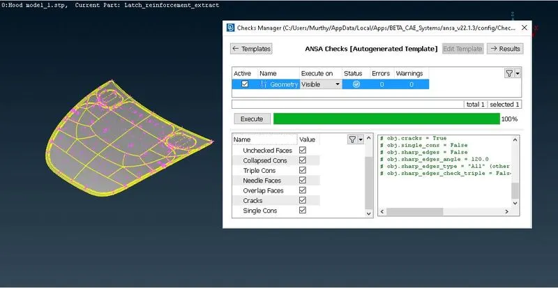
- If found these geometrical error , it can be auto fixed by the tool by the fix option , if not these errors can be corrected manually.
- After clearing all the topological and geometrical errors , once again run the check geometry until all the errors are addressed.
- The above check runs need to run for all the sub-components of hood
- Assign the thickness of the component using 'MEASURE' option available on top tool bar at various locations of component and store the thickness value for every sub-component. This is useful for extracting mid surface of the component.
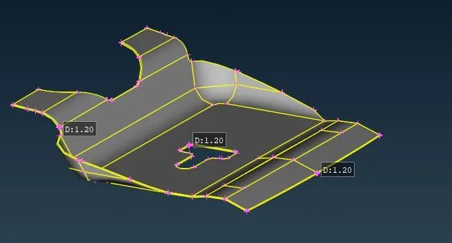
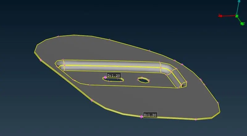
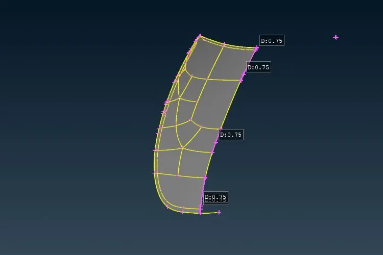
- Mid surface of the component can be extracted by using two methods., using 'OFFSET' or 'MIDSURFACE-SKIN' option from FACES bar on the side tool bar.
- The mid surface extracted by the offset option a new 'PID' has to be set using 'SET PID' option in the 'FACES' bar, but the mid surface extracted by the SKIN option a new PID will be automatically created by the ANSA Tool.
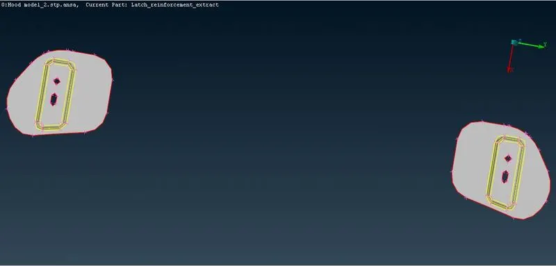
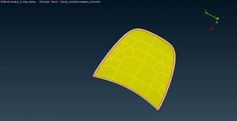
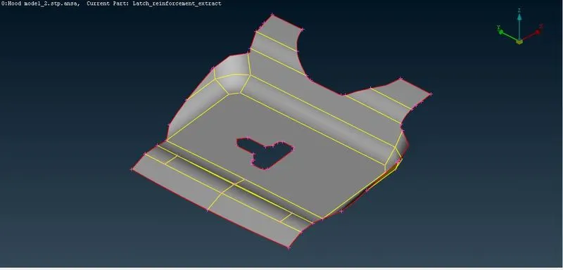
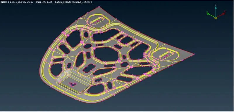
- Again run the check geometry on the mid surface for any topological errors
- By using 'MEASURE' option , check the perimeter elemental length.
- Assign the perimeter elemental length of given value using 'LENGTH-PERIMETR' option in the PERIMETERS option.
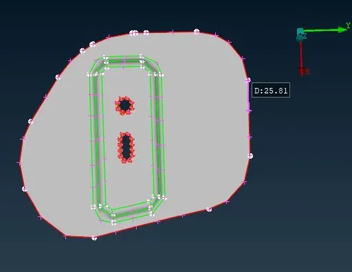
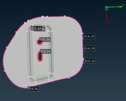
- If there are any holes present on the surface of the component , always the even number of elements on the perimeter of the holes gives better results.
- This can be checked by using 'NUMBERS' option in the PERIMETER bar. Select the cons of the holes and press middle mouse click button to check the number of elements present on the perimeter and alter if any required.
- Arrange the features (holes) of the component parallel to the nearby perimeter for better results
- In the 'MESH PARAMETERS' give the specified requirements for the element and the type of mesh.
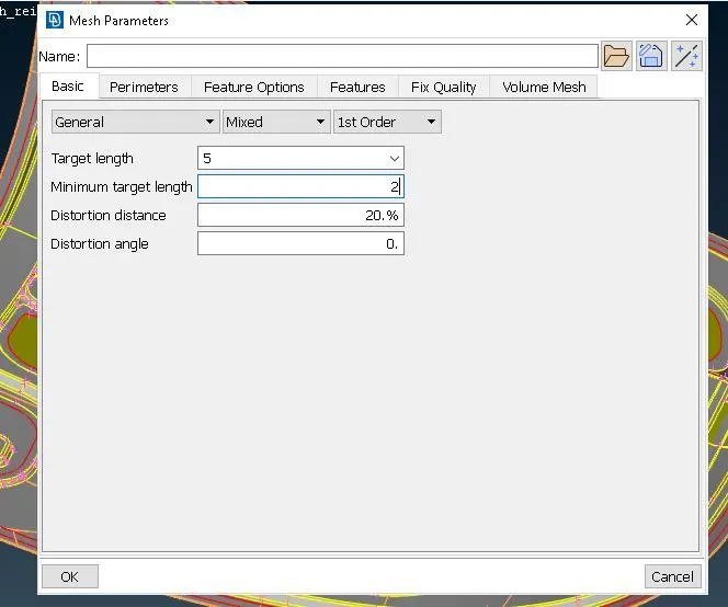
- Give the specified values for the quality checks in the 'QUALITY CRITERIA (F11)' tab. Select all the required quality checks and assign the given values.
- These steps need to be repeated for all the sub components of the hood
- Before generating the mesh , check all the features (holes, fillets, sharp edges etc.,) of the component are captured properly.
- In the outer part of the hood , the elemental quality criteria will get failed in the hemming region due to the fillet having very small surface , De-featuring need to be done by 'CUT' option (deleting one of the featuring line) to capture the fillet properly.
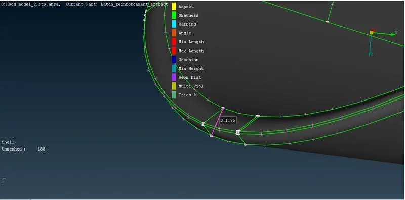
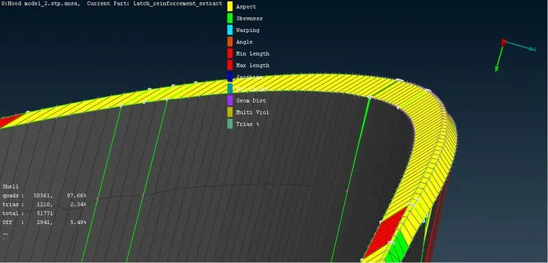
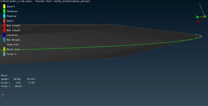
- Delete un-necessary hotpoints and cons which may cause in failing of deploying proper mesh flow.
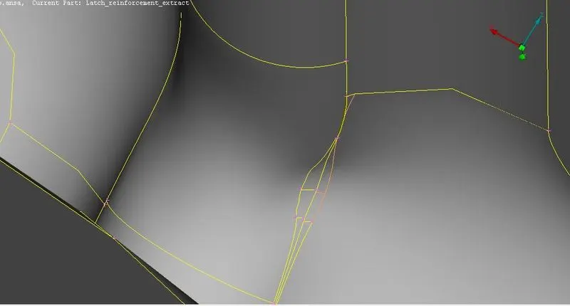
- Run 'CHECK GEOMETRY' for each mid surface extract and fix the issues if any.
- Using 'BEST' mesh in MESH GENERATION tab , generate the mesh on the mid surface.
- The inner extract of the hood component can be split into two halves , as the component is symmetrical through its center . Half portion can be deleted by using 'RMBDL' in FACES option . Once the mesh is generated on one half it can be copied by using 'TRANSFORM' option.
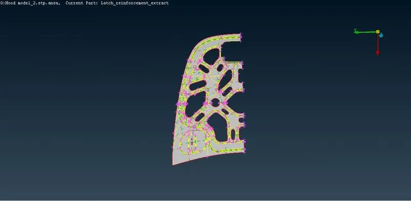
- Optimising the mesh that is generated by using 'MOVE' , 'SPLIT' , 'PASTE' , 'SWAP' commands
- Using the 'IMPOVE' option , the mesh can be regenerated, reconstructed , smoothen wherever required on the component.
- Avoid trias on the edges , back to back trais , opposite trias , trias facing towards each other , distorted quads , trias on fillets.
Learning outcomes:
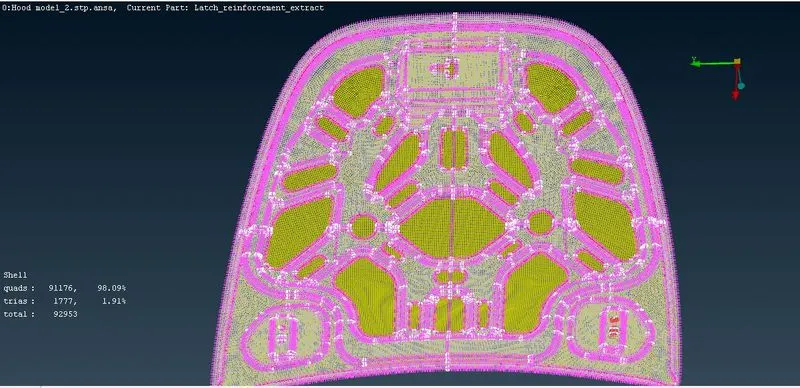
Meshing the sheet metal components including topological/geometrical cleanups , 2D-meshing , creating proper mesh flow , correcting the off elements (elements that are failed).
Conclusion:
A 2D-Mesh has been generated successfully on a sheet metal component following the given quality criteria.
https://drive.google.com/file/d/186KwzXS6t9HeX1r_q8HaF6G1Cnlnxl94/view?usp=sharing