Week 6 - Creating connection for Rear door
Aim: Creating connection for rear door
Procedure:
- Take the geometry (Meshed)
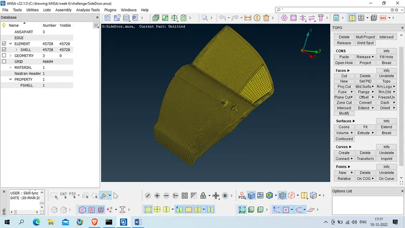
- Create PID for every sub-part as below ( Classic mess- Micros- Set PID- Select part – New – Pshell- Ok Assign details – ok)
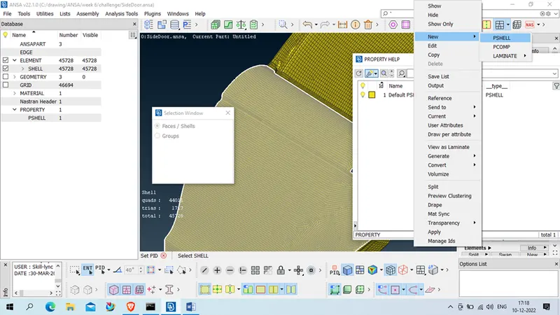
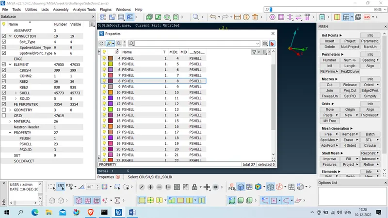
- 1st we will create bolt connection to the door hinges
For that we will create point on COG ( TOPO- point – point on COG – select any closed loop in that Hinges bolt area- and create point by selection )
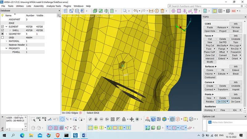
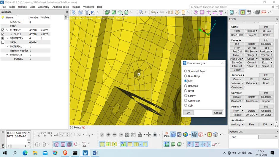
After both created , we will provide connection using ( assembly- connection manager – select bolt-
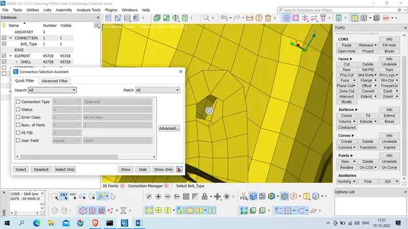
Middle click _ after middle click one pop box generate for connection manage as below
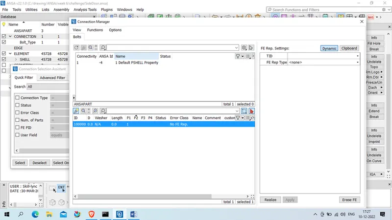
Assign P1 , P2, P3 as per available PID for same bolt
For selection middle click on P1- (Modify – press on modily- Sift+?) – select PID and enter
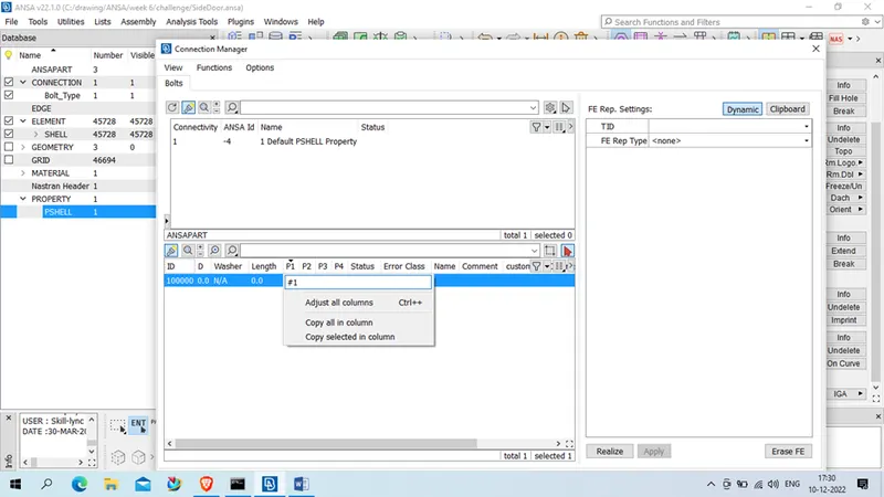
Assign
FE rep type –bolt
Search distance- as much user want like 20,50 etc.
Zone- In/Out X
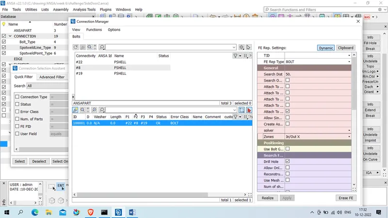
After that press on realize , bolt connection will be deployed ,
Repeat same for all hinge bolt .
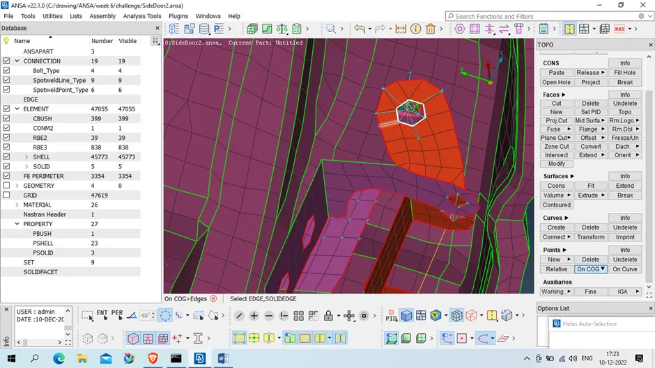
After that this point will be converted to bolt using (Assembly- Convert -3D point – select the point – middle click – select bolt )
After bolt we will deploy connection between hinge and body
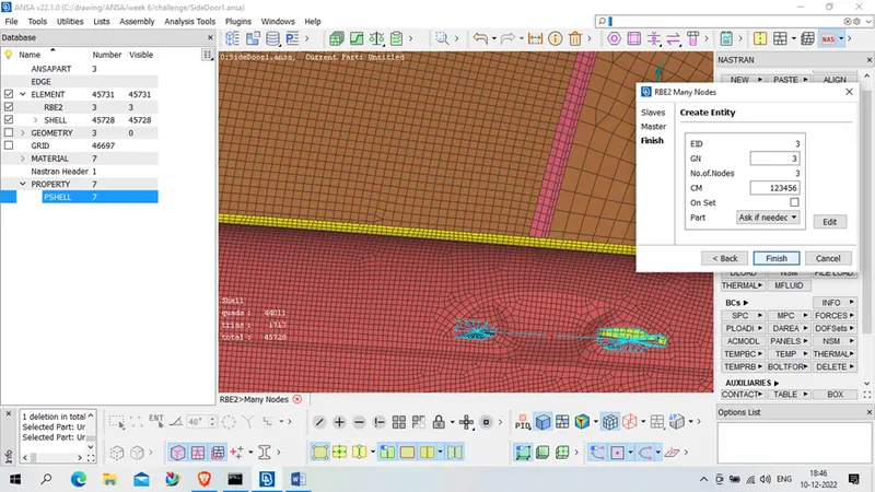
For that we will use RBE2 –many nodes connection in ( Nastran – Elements- RBE2- Many node )
Select the nodes
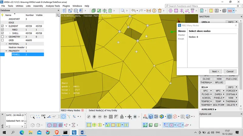
Next-
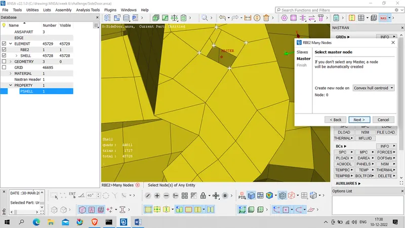
Select Master Node – Next
Create Entity – finish
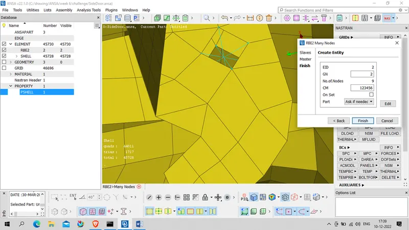
Middle click
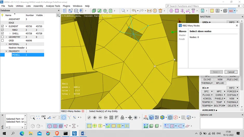
Now RBE2 Connection has been deployed .
Repeat same for all the required location
- After This we will deploy RBE2 two node connection to door hinge and restrict the door movement in Z direction of vehicle
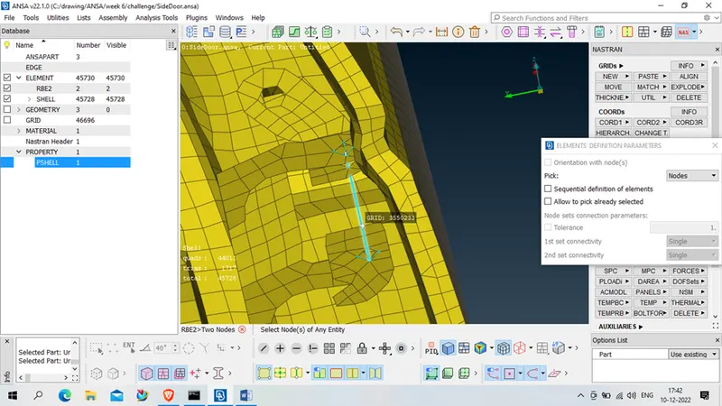
For that we will use RBE2 two node connection in ( Nastran – Elements- RBE2- two node )
And select two node of same hinges as shown below
Press ok and middle click
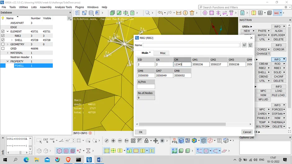
After connection deployed we will go to info (Nastran- element – info ) select the connection and restrict CM as providing only 12345 in CM box
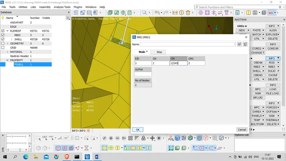
Press Ok
Again RBE2 Box will pop –up
Restrict CM as given below
Repeat same for other one ,
Connect hinge to door by using RBE2 connection in element
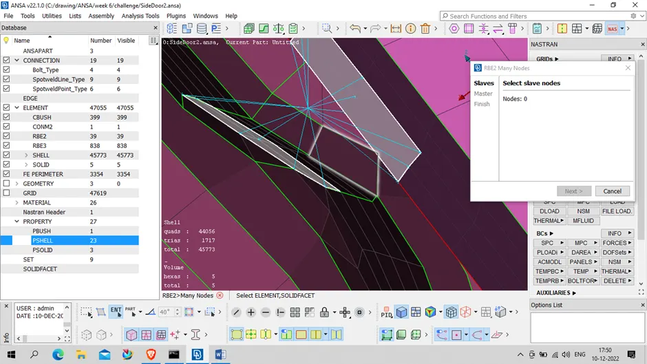
After this our hinge connection is done
- For latches
As our geometry is damage and there we can’t do anything , hence we will avoid connection for latches
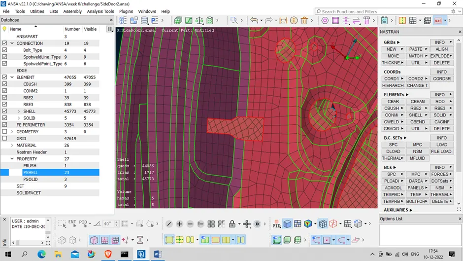
- Now we will deploy connection to glass trail mechanism USING RBE2 elements
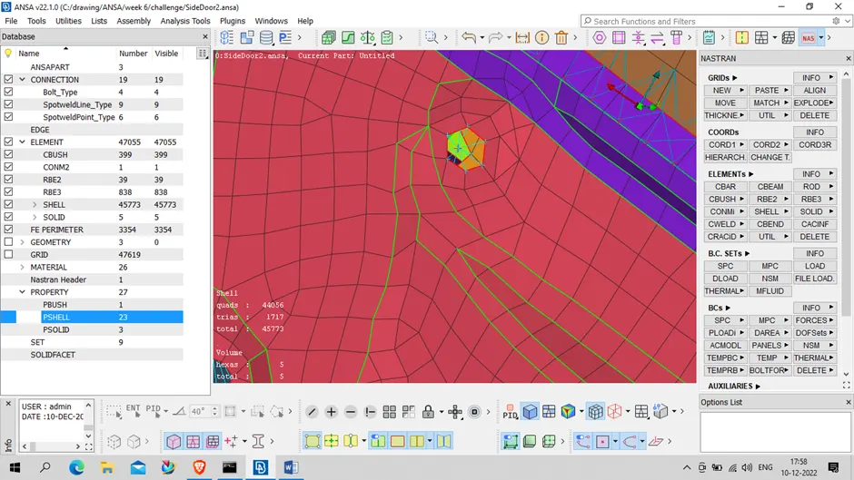
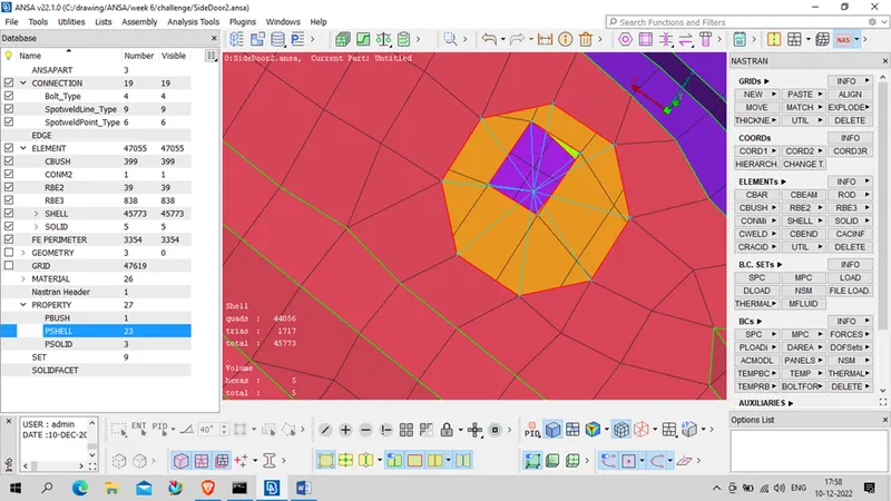
- Spot weld connection
For this first we will create point on COG in topo mode and required location ,
After point , we will convert point into spotweld point
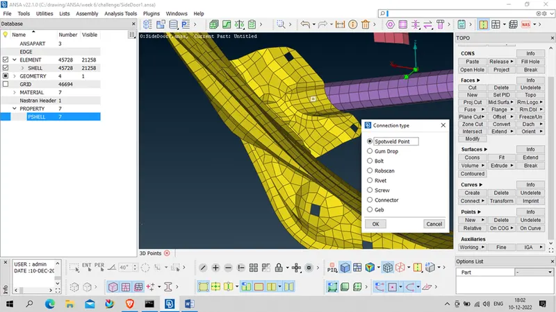
After getting spot-weld point , we will deploy connection for spot-weld using connection manager
Select spot weld point , middle click , assign P1 and P2
FE REP Type – RBE3- HEXA – RBE3
Search distance – 20… etc as per user
RBE3 pinflags- 123456
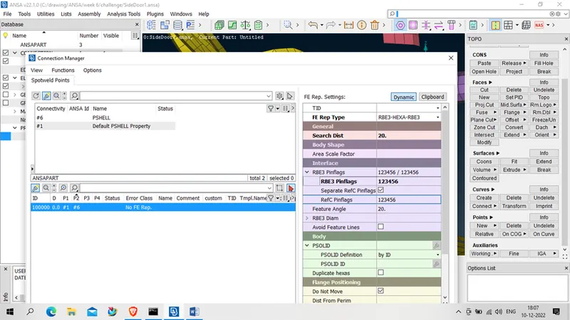
After this we have to create solid is
Body- Psolid – select that and press sift+?, below pop up will create
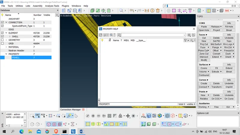
Create new Psolid
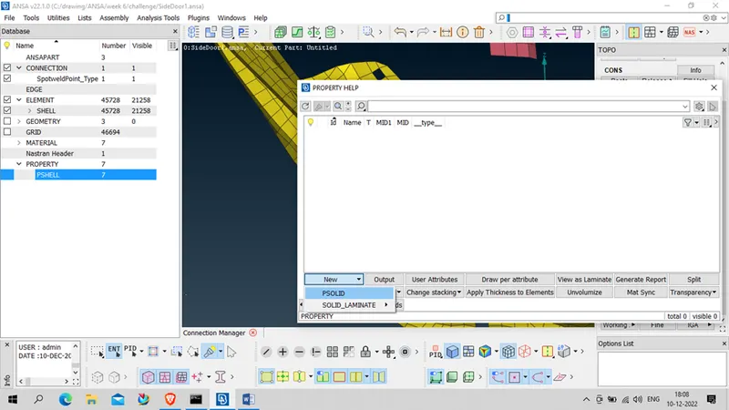
Assign Data like name ,PID, MID etc and press ok
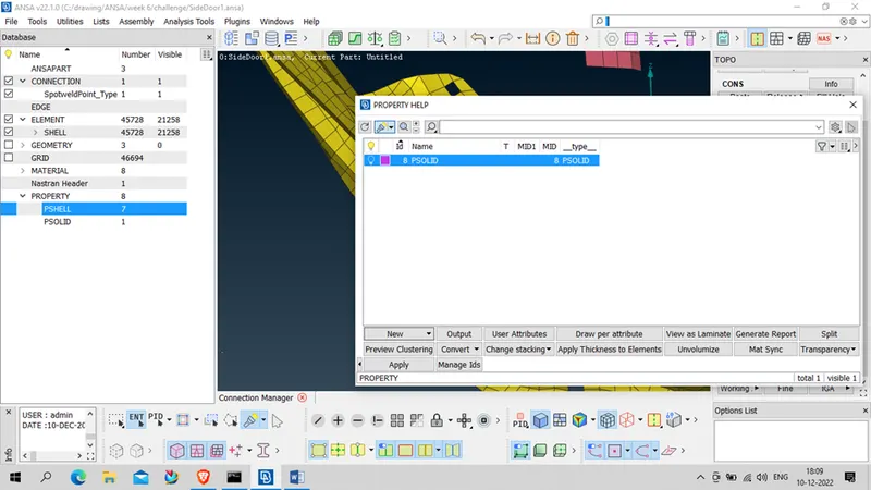
Double click on Psolid created now , it will assign to our connection
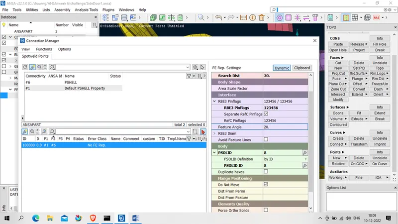
After that – apply- realize, our spot weld connection is deployed, repeated sopt weld connection where required
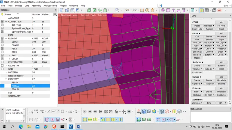
- Now we will apply connection between glass and frame
for that we will extent the strip mesh
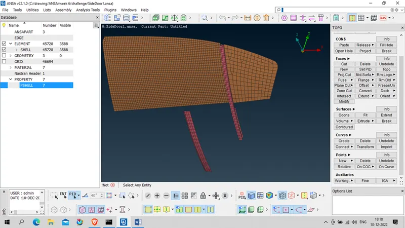
Using Classic mesh – Grid – MV free – selected the element as given below
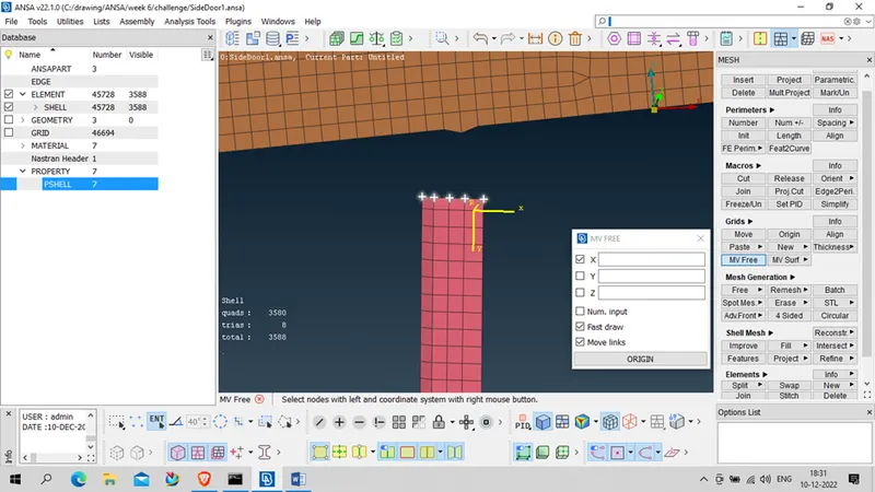
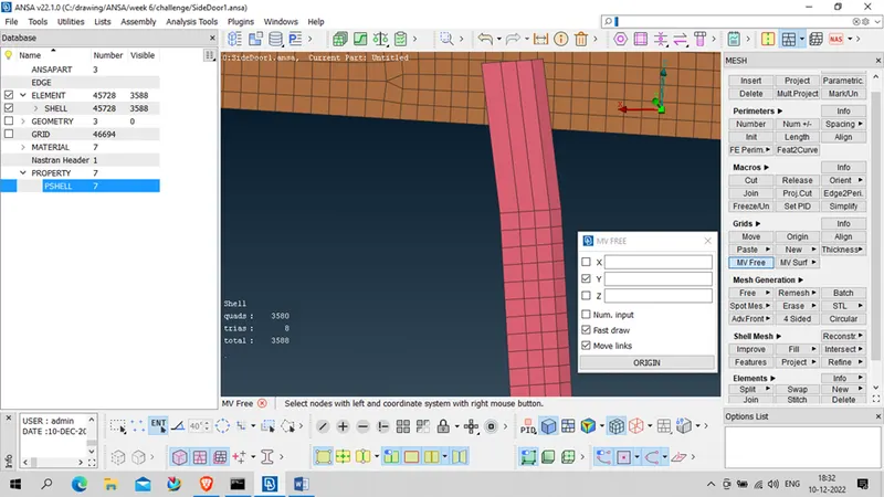
Increased the same in y direction
Correct the mesh using reconstruct mesh ( assign the mesh parameter as 5or 6 first )
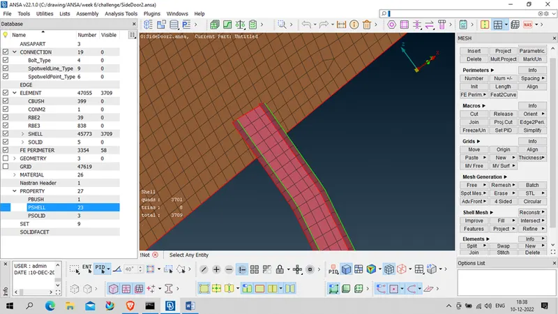
Now deploy the connection in the same using RBE2 connection in elements ( in Nastran deck)
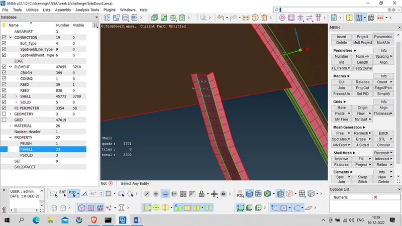
- Now we will provide connection to Door handle
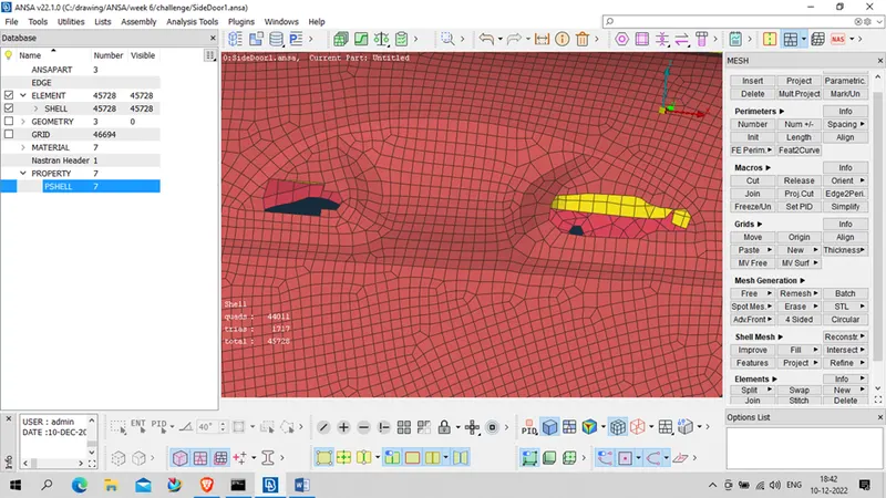
Now 1st we will provide RBE2 Connection to both the handle connecting portion
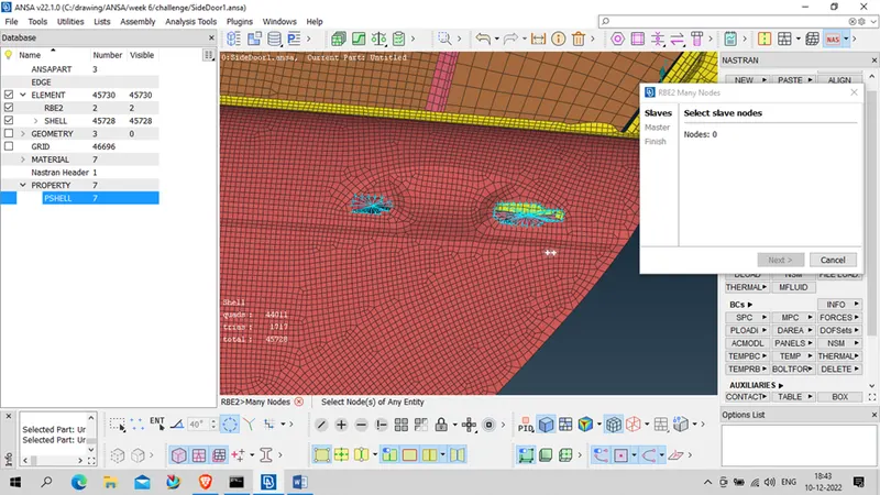
After That we will provide RBE2 between the center of both node
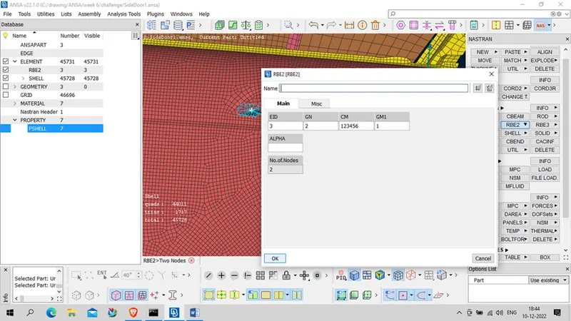
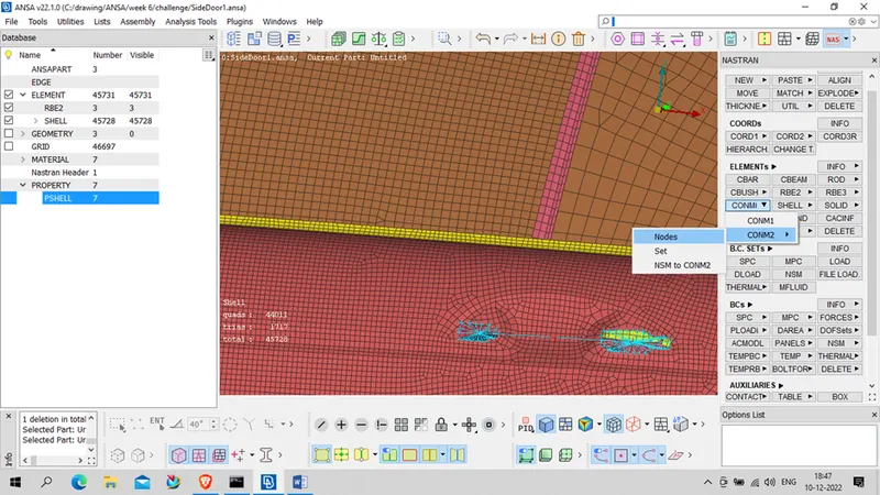
Now we will assign the weight to the node using ( Nastran- element – CONMi- CONM2- NODE-
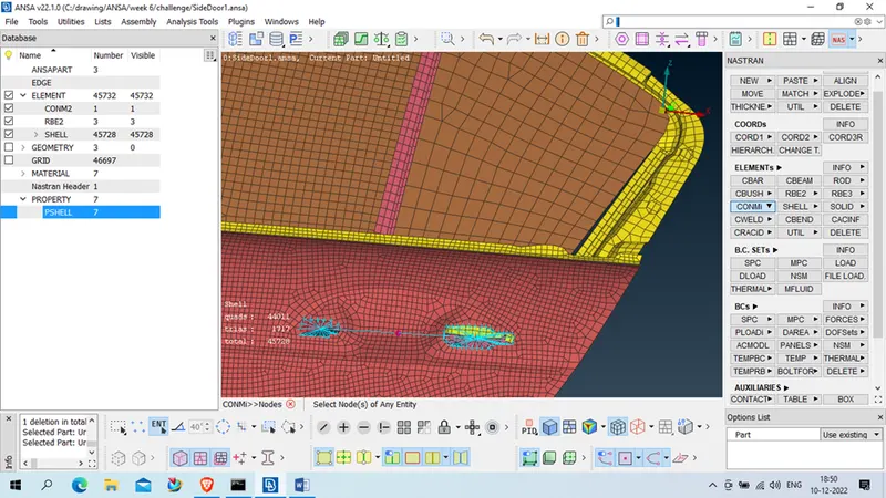
Select the node then below pop up will generate
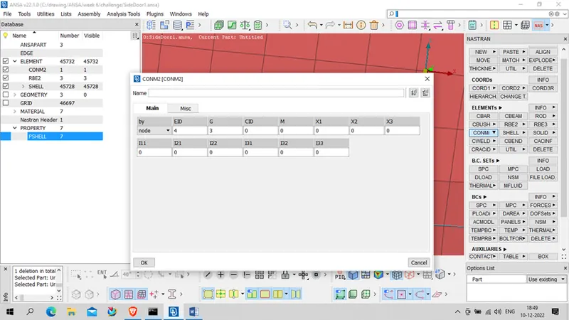
Assign the mass in tonnes (1e-4) for 100 grams and click ok
- Connection for whether strips
1st we will create curve using ( Classic mesh- perimeters – Feat2curve- select the glass edge mesh and click middle button)
Repeat for all side for both class
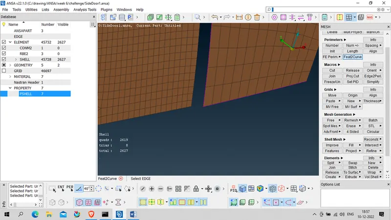
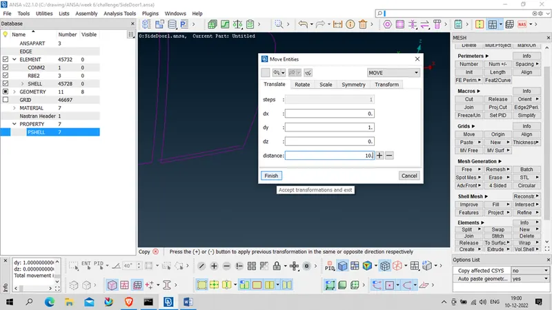
Transform –copy down side curve
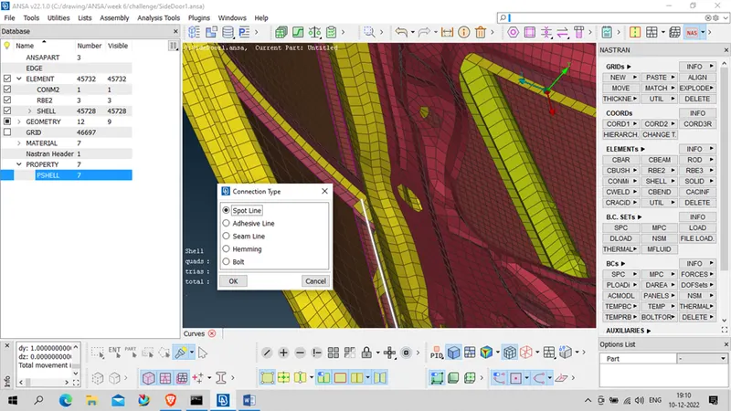
Convert curve to Spot line ( Assembly- curve _ Select curve – middle click – select Spot line – ok ), repeat same method for all the curve
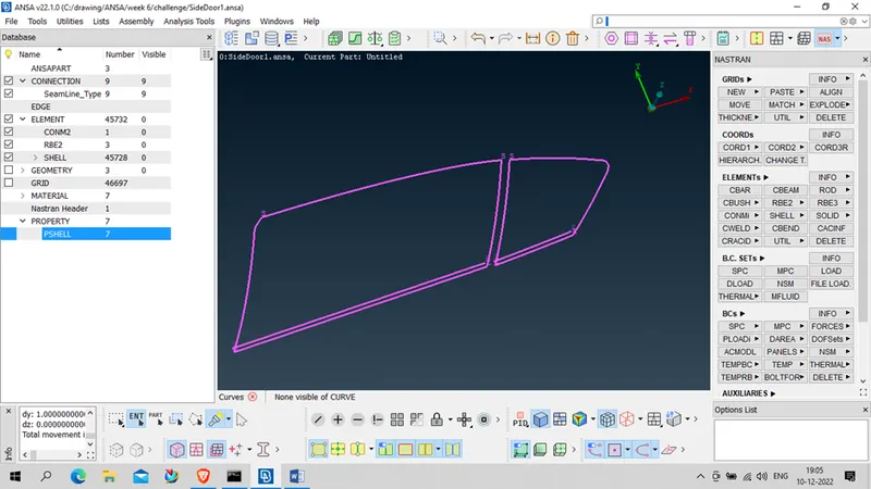
Now we will deploy the connection to curve line ( Assembly- Connection manager- select curve –middle click )
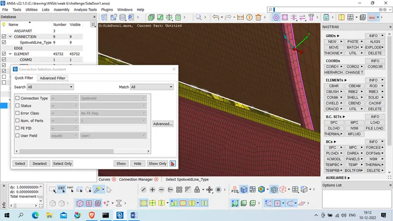
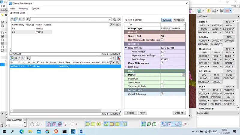
After middle click we will get connection manager box
Assign S, P1, P2
FE REP type- RBE3- Cbush-RBE3
Search distance -50..etc
Keep all branches – Ticked
Create Body-Bush – (Shift+?)
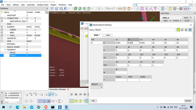
Press ok
Double click on created PBUSH it will assign to connection
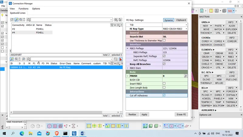
Click on realize , Connection has been deployed
Repeat same for all the spot line curve
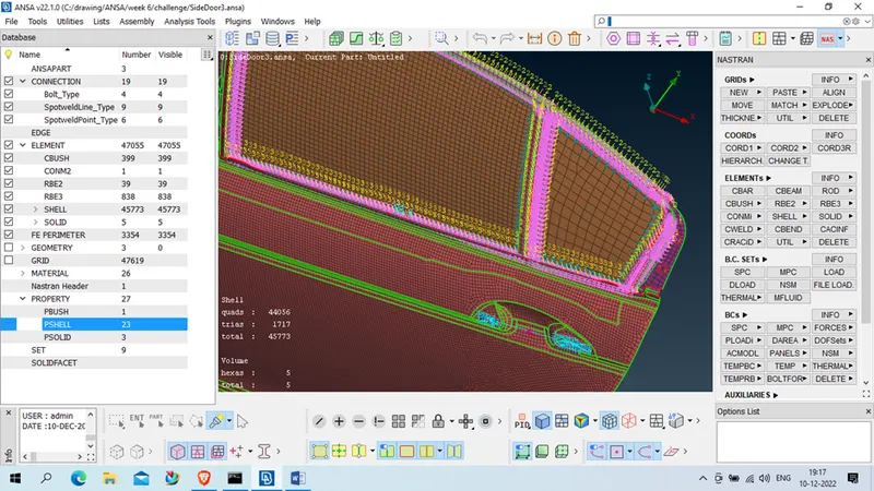
Allign the Pbush cordinate
Open Cbush ( In element ) Its originally form with vector
We will show orient and CID of that
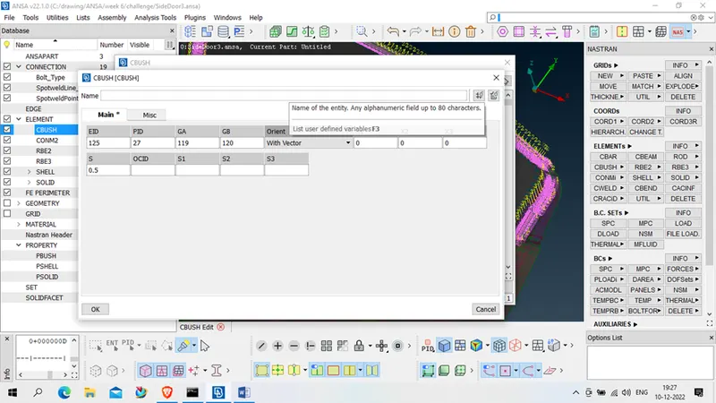
We will change oreint – to With vector and allign CID to 0
Same we will select all the PBush – Right click and select modify
New Modification
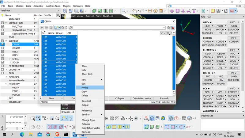
Modify Rule
Orient – with cord
CID -0
Press ok
All the Pbush are now allign with the globle axis of the vehicle

Conclusion : In this week we had learn to deploying connection in nastran deck ( Bolt Connection , Spot weld , RBE2, RBE3, etc.)