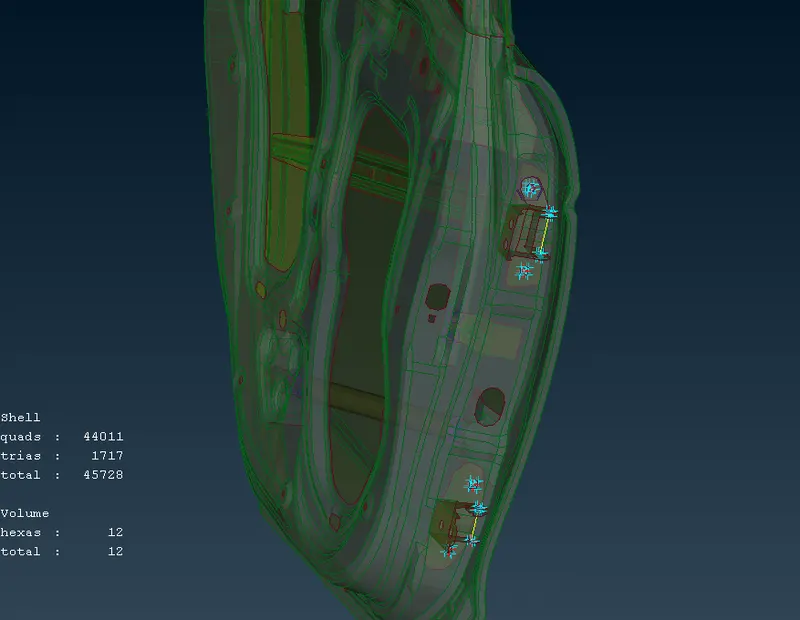
Week 6 - Creating connection for Rear door
AIM - To Create Connections For Rear Door Using ANSA Preprocessor.
OBJECTIVE:
- To create different types of connections which are given below.
- CBUSH Connection for weather strip on window region.
- Spot Weld Connection.
- To create Bolt Connections.
- Creating Hinge connection using RBE2 2 node and many node.
- Applying Mass on the Door Handle.
PROCEDURE:
- First the model is iported into ANSA.
- Then the rear door is divided into several PIDS for ease of assigning the connections.
- Necessary connections points are identified for different connections like CBUSH, Spot weld, Bolt, Hinge and Mass.
- Then the connections are made. The procedure for different connections are listed below with images.
- CBUSH:
- We have to create a curve on the edge of the window using feature2curve option uisng command Modules → classic mesh → perimeter → feature2curve.
- Then we have to convert the curve into spot line using convert option in assembly.
- Then using connection manager from same assembly we have to select the spot line and hit middle mouse button.
- It will open the connection manager where we need to provide spacing, select P1 and P2 (PID's).
- Then in connection manager we have to provide FE representation as RBE3-CBUSH-RBE3.
- Then provide search distance and create Bush PID.
- Then hit APPLY and Realize.
- The CBUSH will be created succesfully.
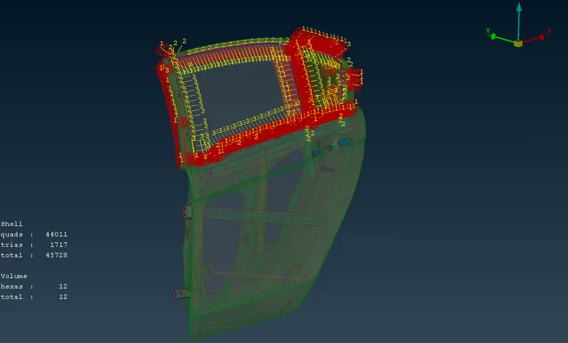
The below image shows the CBUSH created around the window.
2. SPOT WELD CONNECTION:
- First we have to create 3D point. By using command Module → Topo → Points → On COG.
- Then convert that 3D point into spot weld point. By using command Assembly → Convert (Select the 3D point) → Then select spot Weld.
- The using command Assembly → Connection Manager (Select the spot weld point and click middle mouse button) → Select the P1 and P2 (PID's).
- Then give FE Representation as RBE3-HEXA-RBE3.
- Then give the search distance.
- Create the weld PID.
- Then hit APPLY and Realize.
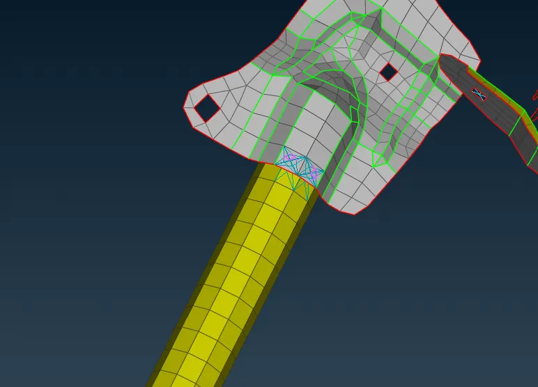
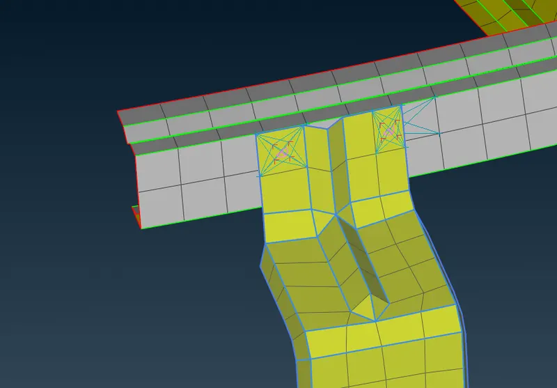
Below are few images of spot weld done in this assignment.
3. BOLT CONNECTIONS:
- First we have to create 3D point. By using command Module → Topo → Points → On COG.
- Then convert that 3D point into Bolt. By using command Assembly → Convert (Select the 3D point) → Then select Bolt.
- The using command Assembly → Connection Manager (Select the Bolt point and click middle mouse button) → Select the P1 and P2 (PID's).
- Then give FE Representation as Bolt.
- Then give the search distance.
- Then hit APPLY and Realize.
The below image shows Bolt connection made in this Assignment.
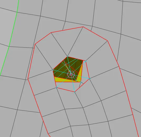
4. CREATING HINGE CONNECTION USING RBE2 - 2 NODE AND MANYNODE:
- At first the from NASTRAN Deck RBE2 - Many nodes is selected to make RBE2 cluster between 2 holes. The same is done on the opposite side pair of holes. The image for the same is shown below.
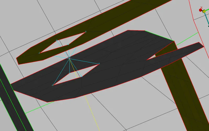
- After that RBE2 - 2 - Nodes is selected from the NASTRAN deck and the two master nodes created by RBE2-Many nodes are joined by RBE2-2-Nodes. This form the Hinge. While setting the RBE2-2-Nodes property Degree of Freedom is given. Below is the iamge for the same.
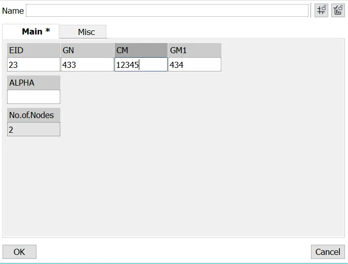
In the above image the CM column is use to give Degree of Freedom. The number 12345 denotes the contarints or restriction of movements in Translational X, Y & Z and Rotaional X & Y Directions.
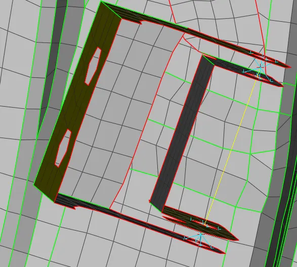
- Thn press ok and teh Hinge connection is created. Below is the image of Hinge connection made in this Assignment.
5. APPLYING MASS AT DOOR HANDLES:
- At first RBE2-Many nodes elements are choosen from Modules → NASTRAN → Elements → RBE2 - Many Nodes.
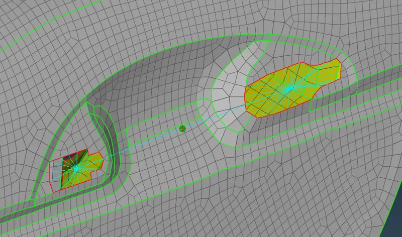
- Then the 2 big empty region near the door handle is filled with RBE2-Many Nodes Elements.
- After that two master nodes of RBE2-Many nodes cluster is connected by RBE2-2-Node element.
- And then the mass is added using Modules → NASTRAN → Elements → RBE2 - CONMi (Defination of concentarted mas element connection).
- In this the Mass is added at the door handles. Below is the image for the same.
LEARNINGS:
- Learn to apply different types of connection in ANSA.
- Learn to identify different types of connection.
CONCLUSINON:
- Applied all the types of connection as specified in the objective.
- Final images of the connection in different view are shown below.
The below image shows the CBUSH Connection.
The below image shows the Mass added on the door handle.
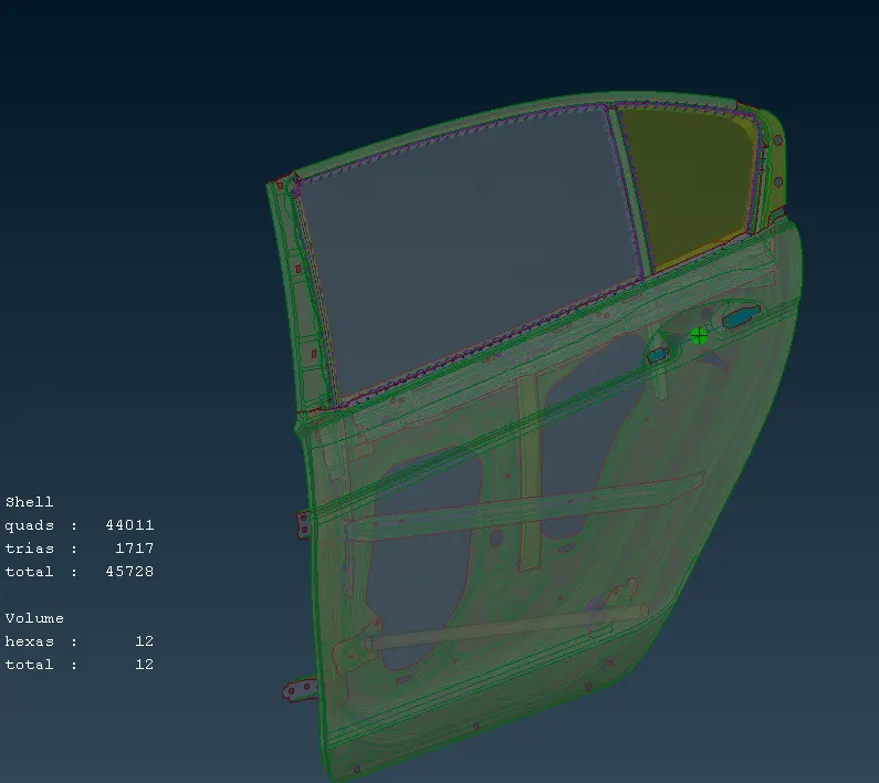
The below image shows the RBE2 connection made at the Door handle.
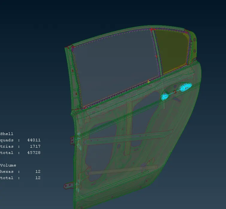
The belwo image shows the hinge and Bolt connections.