Week 6 - Creating connection for Rear door
Aim:
To create connections for the front door by using different 1D elements.
Procedures:
1)Geomentry Check was done and ensure that the CAD model is free from Geomentry errors.
2)PID Assignment
After geometry and topo clean up the meshed models is assigned various PID as per necessary requirements by "Property manager > New > PSHELL > Apply > Selection of the appropriate part"
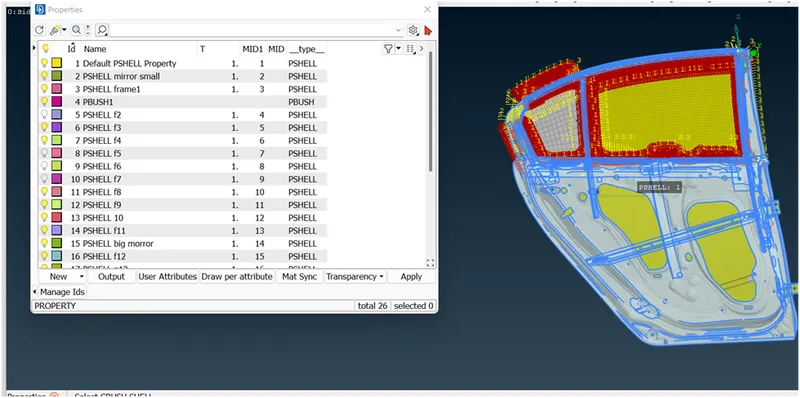
3)Bolt connection deployment
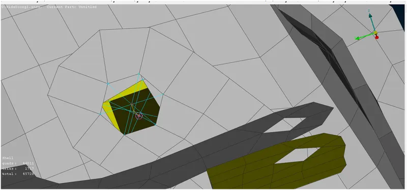
Connection establishment between two hole by using BOLT connection
create Bolt by using cluster RBE2, selecting one hole at a time and join it by cluster RBE2 and to define the bolt body or stem we can use 2-Node RBE2 to make connection among the parts.
4)Spot weld connection
create the Spot weld connection to join the parts, to create spot weld firstly we have to define a 3D point between elements by using ON COG option in geometry Panel, select the Edges and then creating the 3D point between the selected edges, after that we have to convert it into Spot weld by using convert option in Assembly section
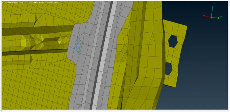
Above Fig :Spot weld through COG method
our connection is not realize yet, for Realizing the connection we have go to Connection manger in Assembly section, here we have to define the parts that needed to joined as P1,P2 and then we have to define the search tolerance and also we have to define the thicker side of the part to create weld at it, after that we have to define spot connection as RBE3-HEXA-RBE3 and then we have to click on Apply and then click on Realize to make the connection.
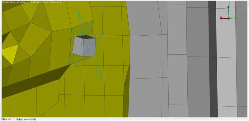
Above fig:Spot weld connection realized
5)Connection Seam welding
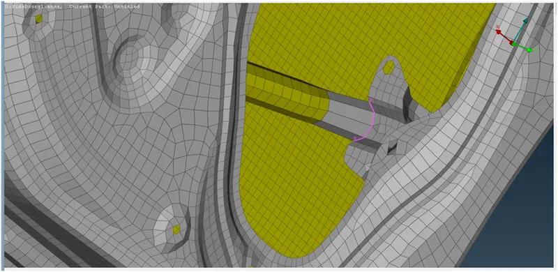
Seam weld connection is also used to connect two mating parts. Generally, we use two types of seam weld connection i.e. overlap shell and Y-joint shell. Overlap shell connection is used when we have to connect two parts which are parallel to each other. And Y-joint shell is used when we have to connect two parts which are perpendicular to each other.
Mesh module ----> Perimeter----> Feat2curv. This command will help to create curve from the CONs. Now we have to convert the curve into seam line. Then using connection manager, we have to select overlap shell in FE representation type. Now overlap shell weld connection is established between parallel mating parts by selecting appropriate sheets in P1 and P2 as shown in picture below.
6)Connection for door Hinge:
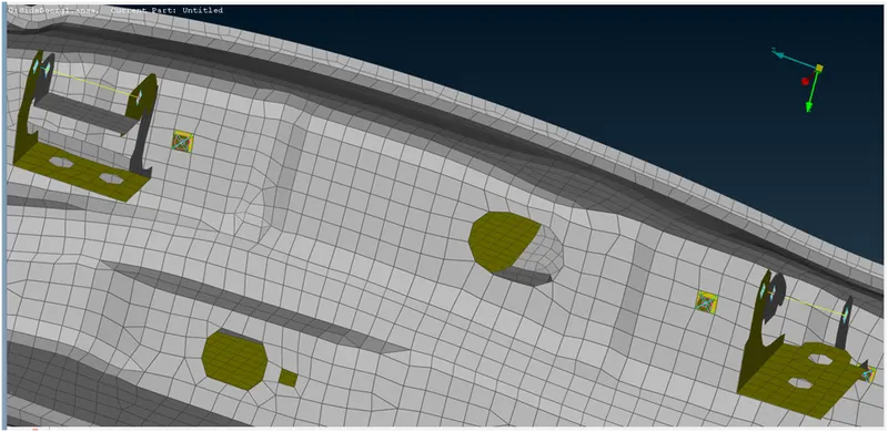
Use RBE2 command in "NASTRAN module > Elements > RBE2>Many Nodes>Select nodes>Ok> Finish" to create bolt connections separately then join the two connections by using "NASTRAN module > Elements > RBE2 > Two Nodes >Select nodes > Ok > Finish".
7)Connection Door Handle
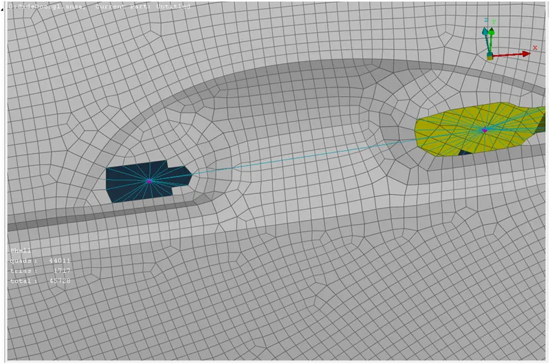
RBE2 command in "NASTRAN module > Elements > RBE2>Many Nodes>Select nodes>Ok> Finish" to create bolt connections separately then join the two connections by using "NASTRAN module > Elements > RBE2 > Two Nodes >Select nodes > Ok > Finish".
8) C bush connection for window Glass
For Door Glass connections create Curves around the glass using "Mesh> Perimeter > Feat2Curve". Then offset the curve on the both sides in Y direction at 1mm distance. Convert the curves into Spotline following that use the connection manager to select the curve and create CBUSH under RBE3-CBUSH-RBE3 by assigning P1, P2, S , Search distance and PBUSH ID. The PBUSH ID is created for all CBUSH connections. Finally click Realize Apply to finish the connection.
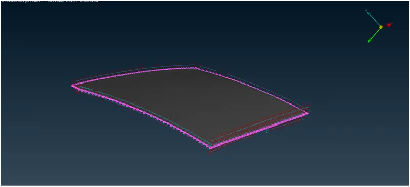
Above fig:C bush connection made on all 4 side of Glass
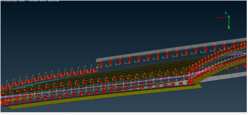
Above fig:Closer view of connection realization on both side of complete glass area
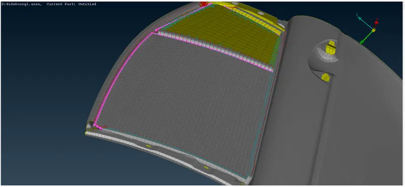
Above fig:C bush connection deployed over the complete Glass panel area
Learning outcome
- 1D element and type of connection.
- Different type of methods to make connection.
- Assigning mass to the body.
- Assigning seam and spot weld connection.
CONCLUSION
Connections are created successfully for given rear door model of a car by using RBE2, RBE3-HEXA-RBE3, RBE3-CBUSH-RBE3 and CONMi element.