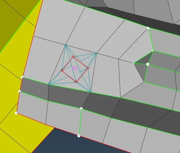
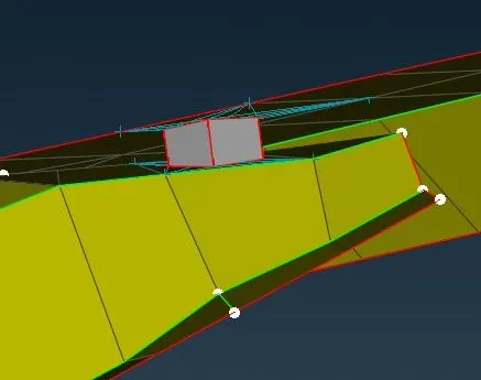
Week 6 - Creating connection for Rear door
Aim: In the given Rear door FE model, we have to create and Apply different PIDs for different components.
Procedure:
The model has been imported to ANSA
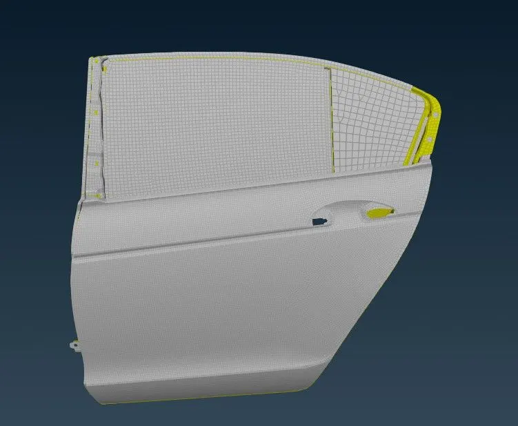
It has been observed that a Common PID is present in the model.
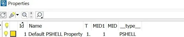
So, we have to set the different PIDs for every FE component.
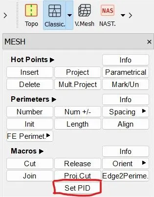
For setting PID, go to Mesh module open Macros group select Set PID and we can create a new PID
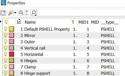
After Giving the separate PIDs
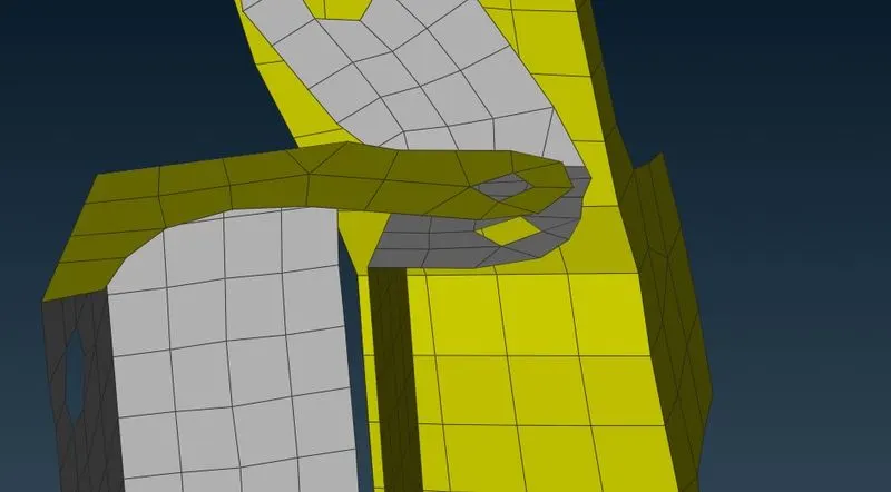
Bolt:
We can see here there is the area where we can set a Bolt
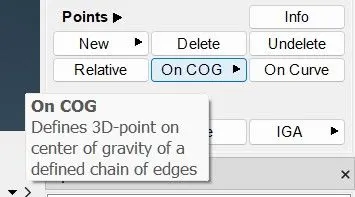
Now go to Topo module and select On COG in Points Group ( TOPO > Points > On COG )
COG: Center of Gravity
Select the Edges, so now we can see the 3D box
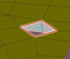
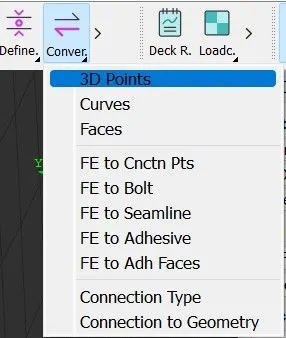
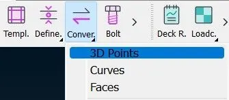
Now go to Conver and select 3D Points.
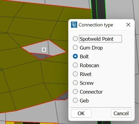
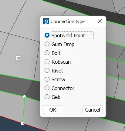
Select the Bolt in Connection type.
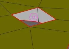
So now we can see a Bolt on the center.
Now go to the Connection Manager
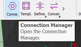
And select the Bolt.
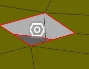
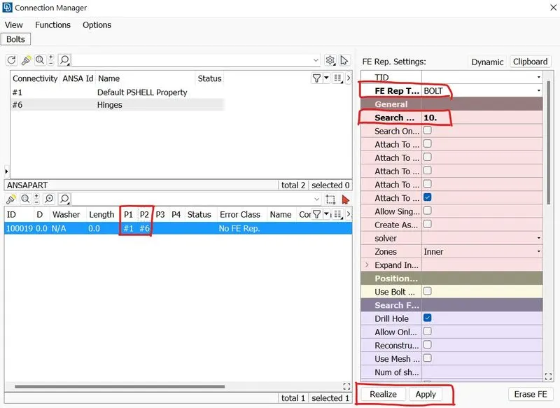
Then we get the connection manager slide, now here we have to give the Property number which we have to create the bolt and the number should be including symbol #.
Give the FE rep type as Bolt and keep the search distance value of 10
then apply and realize.
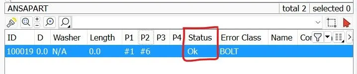
When we give apply and realize we can see "OK" in the status.
And Here we get the Bolt.
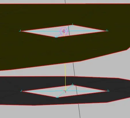
Cbush:
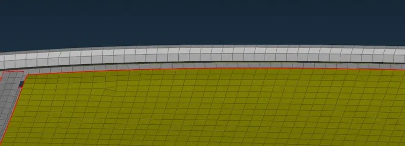
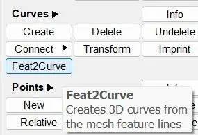
Go to Topo module and select Feat2curve in the Curves group
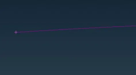
Select the perimeter and make a curve.
With FE mode.
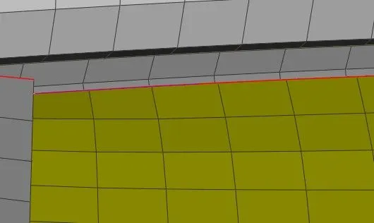
Without FE mode.
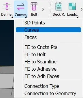
Select Curves in Convert.
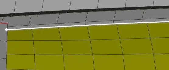
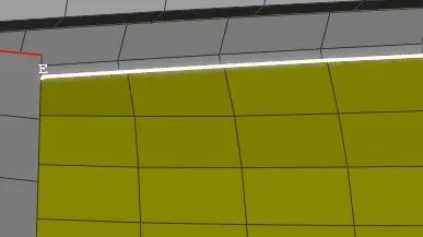
Select the curve.
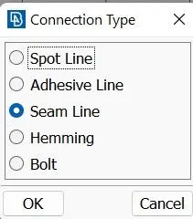
Now select the Seam Line.
then go to the connection manager
Again click on the curve which we have created
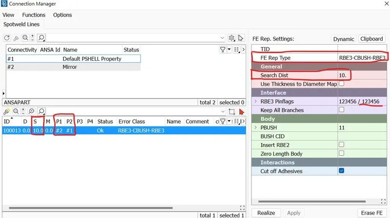
Here we have to give the surface value 10 select the property and give the P1 and P2 values (give # before giving the value) then FE rep type must be RBE3-CBUSH-RBE3 and search distance 10 give the RBE3 Pinflags value as 123456 and in the Body segment in PBUSH give Shift + ? and now give apply and realize.
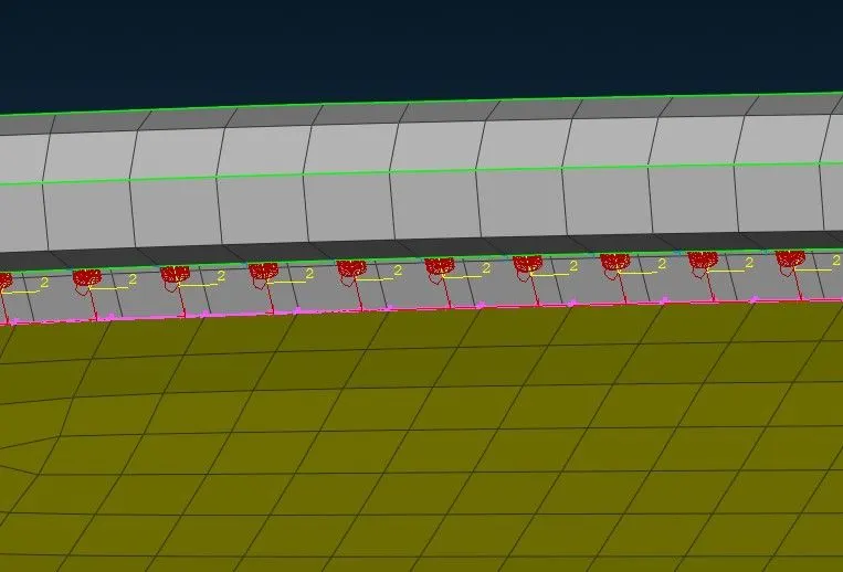
Now we can see the CBUSH has been formed.
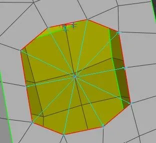
Now we are filling this hole by creating an RBE2 connection.
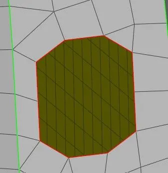
Select NASTRAN
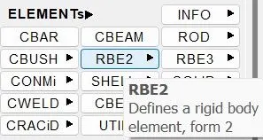
In Elements group select RBE2
Select the nodes.
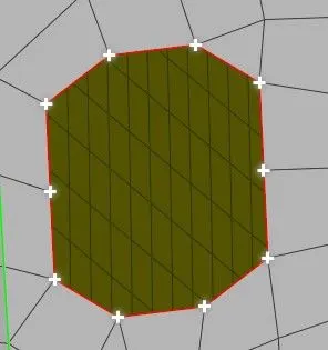
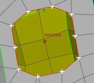
Now give the middle mouse click.
Spot welding:
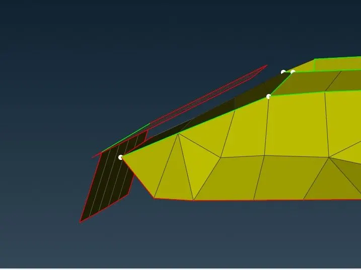
Here we are giving the spot weld.
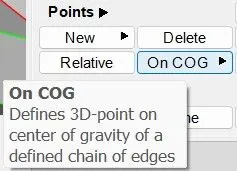
Go to the Topo module, in Points groups select On COG.
Now select the edges.
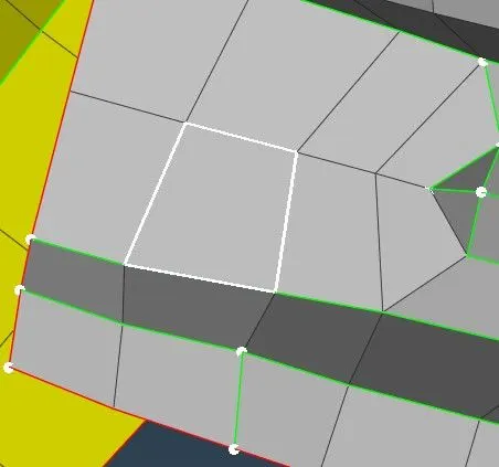
After selecting the edges we can able to see the Blue color 3D box.
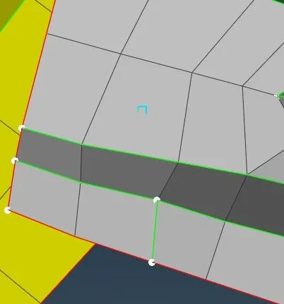
Now go to the covert and select the 3D Points.
and select the 3D box, then we can select the Connection type as Spotweld point
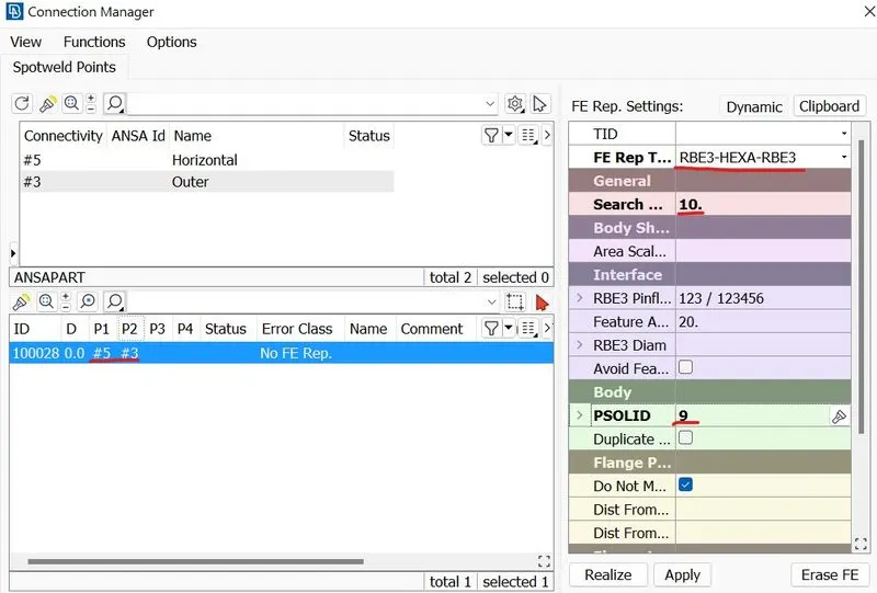
Now go to the Connection manager and select the spotweld point
Now we can see this interference, here we have to change the P1 and P2 values and the FE Rep Type is RBE3-HEXA-RBE3 and the search distance is 10 then in PSOLID give Shift + ? and select the PID where we have to keep the Spot weld. Then apply and realize.
Now we can see the Spot weld has been done.