Week 6 - Creating connection for Rear door
Aim: For the given Rear door FE model, create and apply different PIDs for different components and perform suitable connections.
Types of Connections:
1. Bolt connection
- Bolt connections are formed from two or more holes, which are either shell or solidly meshed. Mostly, bolt connectors consist of a head, washer, body, and the nut of the bolt, by selecting among the provided options. The specified elements of the head and the nut connect the centre of the hole to the nodes of selected edges or perimeters of the hole.
2. Seam weld connection
- Seam weld connections pass through continuous weld lines which have more structural rigidity than spot welds.
- When taking seam length as a reference, we represent it in two ways i.e. one is overlapping the shell connection (particular in parallel positions of the joints) and another is Y shell joint (for perpendicular positions of the part connections).
3. Spot weld
- Spot welding is a form of resistance welding. In this method welding of two or more metal sheets is done together without using any filler material by applying pressure and heat to the area to be welded.
4. RBE2 elements
- These RBE2 elements will form a set of nodes such as slave nodes (dependent nodes) and master nodes (independent nodes). Distribute the loads equally to each and every element irrespective of their independent nodes.
- It will consist of the node IDs, Degrees of freedom, and all other properties related to them.
Procedure:
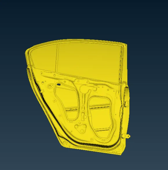
1) Open the given rear door model into ANSA from file>open>browse
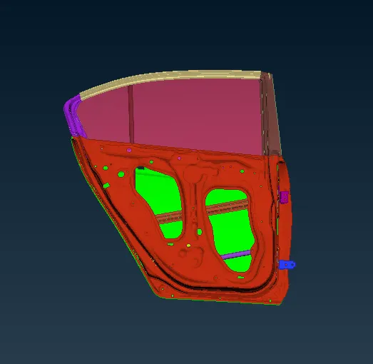
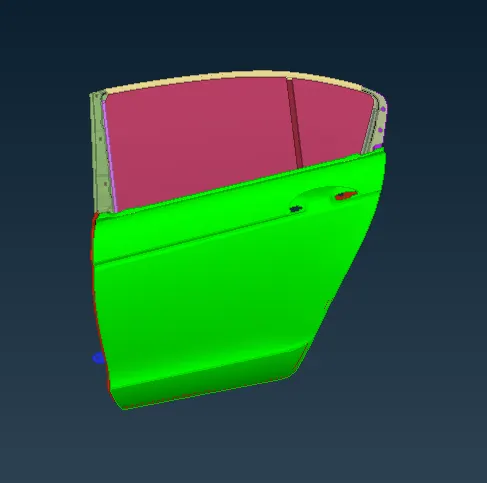
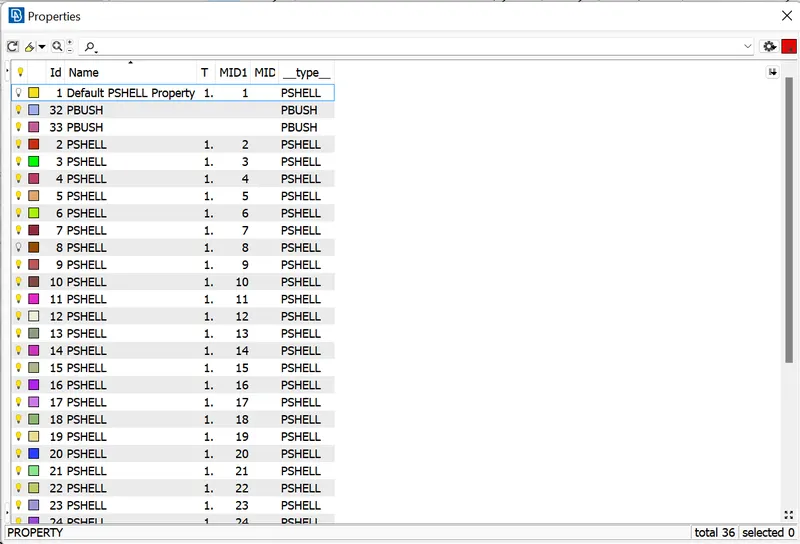
2) Set PID by creating a separate PID for all the door parts. Click Set PID>chose face/shell>select part. Then middle click on the mouse button opens the p_card. Right-click to open a new p_card for assigning the property to that part.
3) Creating connections:
A) Creating an RBE2 connection:
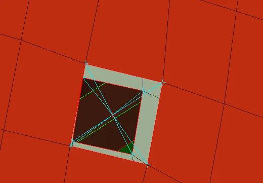
a) Creating RBE2 from many nodes
Navigate to NAST>ELEMENTS >RBE2>MANY NODES. Then select the needed nodes for making the connection.
b) Two-node RBE2
Navigate to NAST>ELEMENTS >RBE2>TWO NODES to create a two-node RBE2.
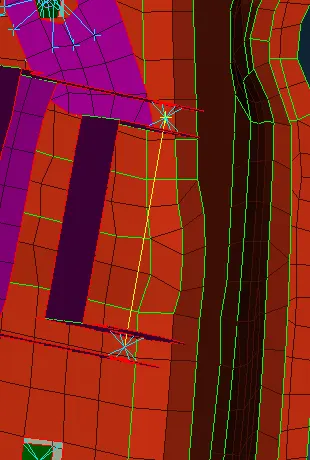
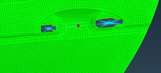
The handle connection is an RBE2 element that can be used. Navigate to CONMI>CONM2>NODES. Then select the nodes in order to give the mass representation of the handle.
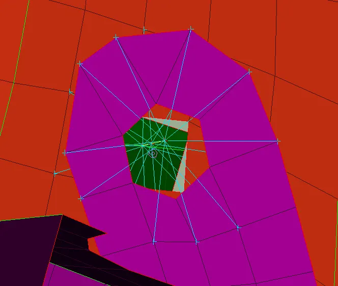
B) Bolt connection:
First, create a 3D point on CoG. Navigate to TOPO> POINTS>on COG. Next, convert the point into bolts points by making the connection by using the connection manager. Select the p1 p2 p3 and make the connection of bolts in the FE rep. settings
C) RBE3-HEXA-RBE3 connection:
First, create a 3D point on CoG by navigating to TOPO>POINTS>on COG. Then convert the 3D point into a spotweld point. Make the connection by using the connection manager. Select p1 p2 and make the connection of RBE3-HEXA-RBE3 in the FE rep. settings. Lastly, create the PSHELL for this connection.
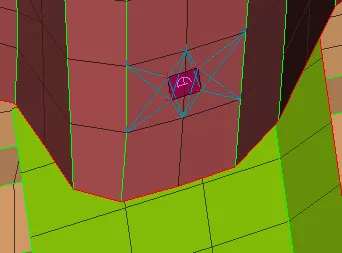
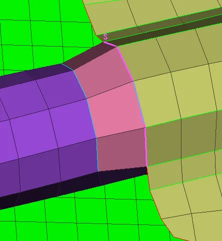
D) SEAM WELD connection:
Create a line by using the feat2curve option. The line is converted to a curve to seam weld. Make the connection by using the connection manager. Select p1 p2 and make the connection of OVERLAP-SHELL in the FE rep. settings. Lastly, create the PSHELL for this connection.
E) RBE3-CBUSH-RBE3 connection:
Create a line by using feat2curve. Offset the bottom line at a distance of 10. This line is used to convert the curve to spotweld weld. Select the p1 p2 and make the connection of RBE3-CBUSH-RBE3 in the FE rep. settings. Create the PSHELL for this connection. Make all sides of the line separately and change all the CBUSH into a global axis. Create orient and CID for all CBUSHES.
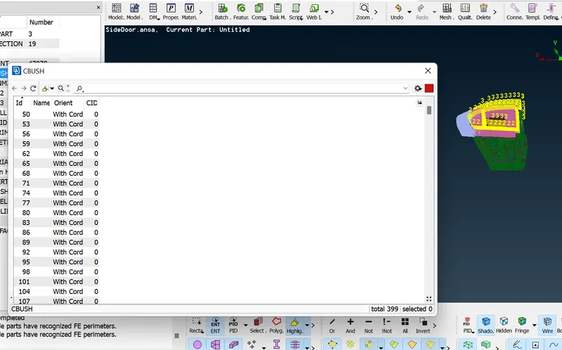
Image of full connections:
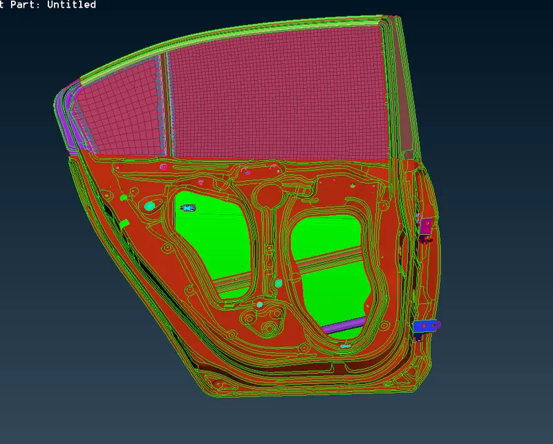
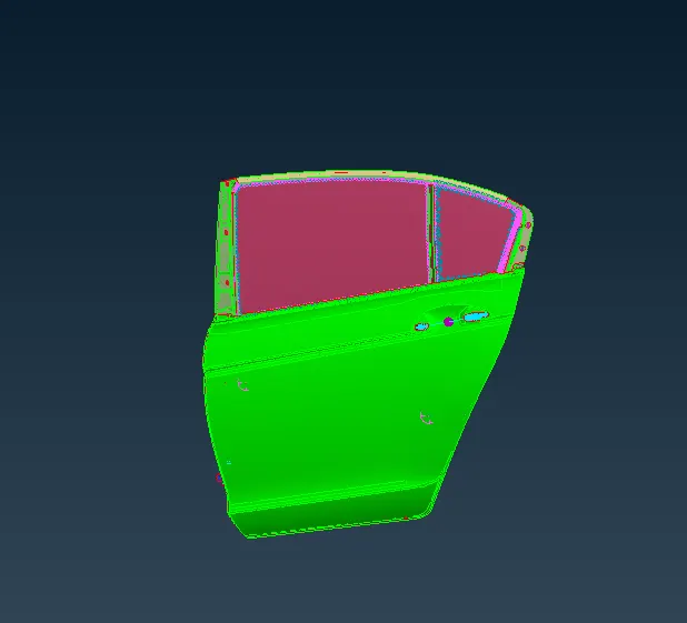
Conclusion: This challenge has been successfully completed and different connections have been generated on the given rear door part to represent the real door connection of the vehicle body.