Week 6 - Creating connection for Rear door
Aim- For the given Rear door FE model, Create and Apply different PIDs for different components. By using the same technique and the elements as shown in the video, Perform suitable connections.
Procedure-
1.Open the given model in ANSA.
2.As the provided model is only FE and there's no geometry, we need not to check the geometrical erros as we usually do.
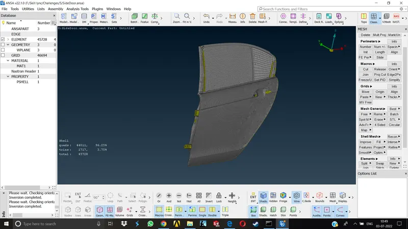
3.The PIDs are not assigned, all the features are bundled in a single PID, so our first job is to assign different PIDs for different components.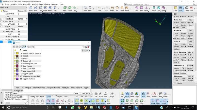
4.Now, we have to decide which type of connection is suitable for given parts. As we are not provided with the specific connection data, we need to observe different parts and imagine how they should be connected ideally.For example, the hinge connection is pretty common to all of us as we have already seen a lot of car doors connections , it is obviously a bolt on connection.
5. In this particular model the most common connection types will be Bolt-nut connection, 2 or more parts connection without nut-bolts, spot weld connection, seam weld connection, bushing connection for window glass,etc. We will be taking a look at them one by one.
BOLT CONNECTION-
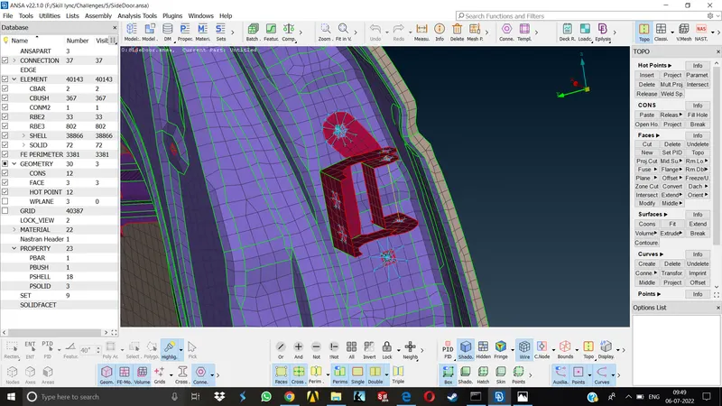
As this is a hinge, it will be connecting the door to the body of the car and the door will be pivoted around the hinge in order to open and close it properly. As the cad of the body was not available, connection of hinge with the door body only is represented as bolt on connection.
We can either represent the connections manually or automatically. The advantage of doing it automatically is we can change so many settings and modify the connection any no. of times as we want. But when we deploy it manually, if we have to change the type of connection later on, we have to delete the connection previously made and reselect the nodes and all the other areas and establish the connection manually again.
AUTOMATIC CONNECTION
To acheive this type of connection we can create a 3D point where we want the bolt connection, Convert that 3D point into BOLT CONNECTION then go to the connection manager, choose the connection type as BOLT in selection assistant,again select the connection type as bolt in FE Representation settings,Give the proper search distance,Choose a proper zone type to be established, select the body type as RBE2, select the parts to be bolted (P1/P2) and click Apply and Realize.The bolt connection will be established, 2 rigids will be formed in case of 2 part connection and the middle line will represent the stem of the bolt.
As the door will be pivoted along the global Z direction, we cannot keep the Z DOF restricted as it will prevent the door from opening and the connection formed will be wrong, So before applying the connection we have to keep the DOFs uptil 12345 only.erase the 6 as it will be representing the Z axis.
MANUAL CONNECTION
Go to the Nastran Deck, Elements>RBE2> (Two noded/Many noded)
select the many noded connection for representing the rigid connection, select the nodes on the area where we want to represent the connection,hit middle click and the rigids will be formed. Now to represent the stem of the bolt we have to select the 2 master nodes of the rigid and establish a two noded RBE2 connection there.
For the connection other than bolt(parts within the subsystem) we can represent them manually as clustered connection RBE2 , the master node for selected parts will be common.
Deciding criteria for the type of connection.-
1.We use bolt connection wherever specified or generally where two different subsystems needs to be attached.
2.If we have to represent the connections within a subsystem ( parts of the same subsystem) we generally use the manual method and represent many noded RBE2 connection.
3.If we have to connect two different components where there are no holes for representing the RBE2 connection or bolt connection, generally these will be sheet metal components adjecent to each other and if they represent very small components, we use spot weld type of connection to represent them.
4.IF we have to connect two components representing a structural attachments with the model where they have to bear a lot of load,stresses as compared to simple components we use seam weld type of connection.
5.For any attached entities to the model such as Door handle or Mirrors, we need not to represent the whole FE representation, we can just create many noded RBE2 conection where they will be mounted, create a two noded connection for connecting different mounting positions and define a mass on the COG of the entity.
6.For representing the connection between window and the door body, we will be using CBUSH type of connection. For this we have to create curves along the body of window, convert them to the spot line connection and then going to connection manager and select P1,P2,P3 accordingly, specify the space between the bushes, create a new PID for bushes and deploy the connection.
SPOT WELD CONNECTION-(RBE3-HEXA-RBE3)-
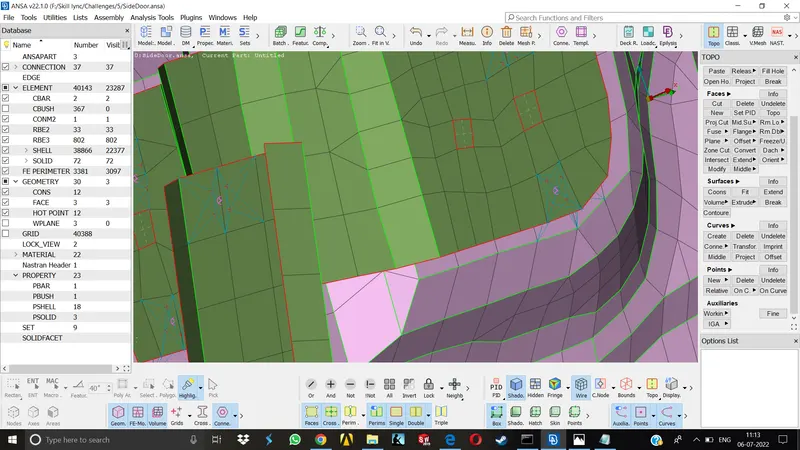
Create a 3D point on the COG of the area where we want to deploy connection
Convert that 3D point to spot weld type
Select the connection type as Spot weld in Connection selection assistant
Go to connection manager assign the PIDs of the parts we want to connect, select the proper FE Representation type,assign proper search distance, assign proper DOFs, create and select the new PID for the weld element, click apply and realize.The weld connection will be deployed now.
SEAM WELD CONNECTION- (OVERLAP SHELL for parallel parts, Y-JOINT SHELL for perpendicular parts)
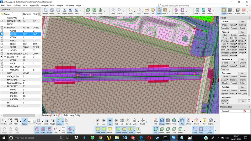
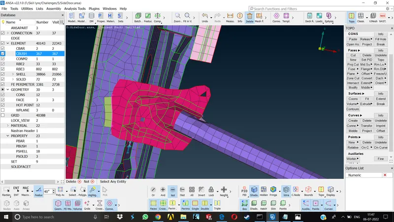
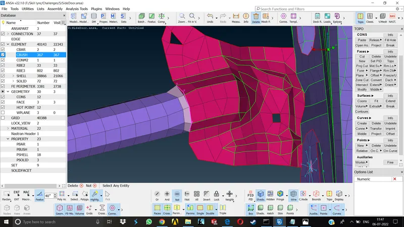
Create a curve along the area on which we want to deploy seam weld
Convert that curve into seam line
Select the connection type as seam line in Connection selection assistant.
Go to connection manager assign the PIDs of the parts we want to connect, select the proper FE Representation type,assign proper search distance,assign the base sheet info manually or keep it to automatic,assign proper weld step distance,assign the type of weld we want i.e. primary row/offset row/double row(double row recommended), create and select the new PID for the weld element, click apply and realize.
CBUSH CONNECTION - (RBE3-CBUSH-RBE3)-
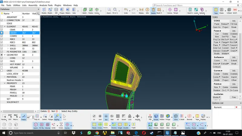
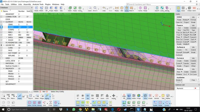
Create curves along the area where we want to deploy the connections
convert them curves to spot line by selecting them one by one
Select the connection type as spot line in Connection selection assistant.
In the connection manager apply proper spacing for the bushes, select the parts between which we want the bush coinnection,give proper FE rep type, assign search distance,create and apply new property for the cbushes,click apply and realize.
repeat this for all the four sides of the window.
One thing we need to keep in mind that once the CBUSH is formed, we need to assign proper orientation to the vectors of the cbushes. We have to align the vector direction of cbush with the global co ordinates of the model to avoid any kind of deviations in the model.
Learning Outcomes-
1.Basics of connections
2.Types of connections
3.Deploying different types of connections on the given model
Conclusion - The connection part was new and little bit tricky to understand. I have stumbled across many difficulties while deploying different type of connections and learned a lot of new things in this particular challenge. After doing this challenge i can perform connections on basic models for sure.