Week 6 - Creating connection for Rear door

Week 6 - Creating connection for Rear door
Abhishek Anil Patil | Course Title | 24/06/2022
Objective
This week, the connections for the front door by using different 1D elements are taught in detail.
Now for the given Rear door FE model, Create and Apply different PIDs for different components. By using the same technique and the elements as shown in the video, Perform suitable connections. (No thickness need to be assigned to FE as intention is just to deploy connections)
(Refer “Model Requirements” in “Grading Policy” to know what to be done in the model)
Write a detailed report on why you choose a certain type of element for connecting certain parts of the door. ( Refer “Report Requirements” in “Grading Policy” to know what to be added in the report)
Click here to Download the Model
Note:
1. The given model is not 100% accurate, few features might be missing in CAD. Ignore such and only work with the given features/FE in the model.
2. Apply some alternative methods if any method is not working.
CAD model
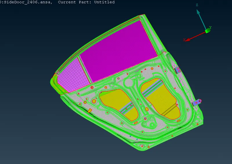
Set different PIDs for the model after importing it in the ANSA environment
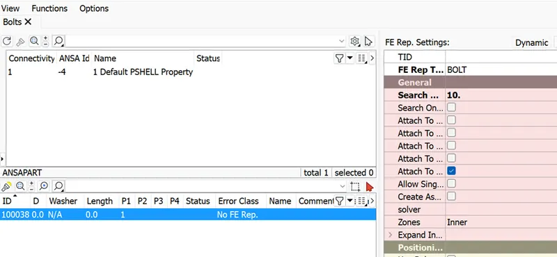
BOLT connections
Go to Topo à points à COG
Create a point in the hole
Go to convert à select the point and choose Bolt
The go to connection manager
Enter the P1 and P2 PID nos and open the FE rep type and choose Bolt
Enter search distance as 10
Then click realize
Spot weld connections
Go to Topo à points à COG
Create a 3d point on the overlap node
Go to convert, select the 3D point and choose spotweld point
Go to connection manager
Select spot weld
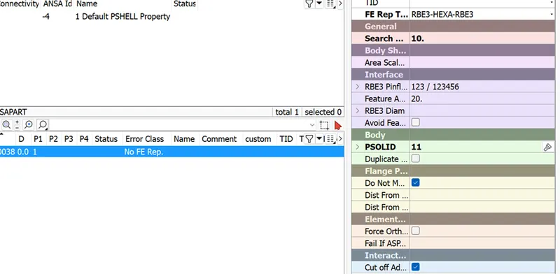
Enter the P1 and P2 PID nos and open the FE rep type and choose RB3 HEXA RB3
Enter search distance as 10
It requires a PSOLID PID, so create a PSOLID and enter the pid number in the options
Then click realize
Spot weld connection
Go to perimeteràfeat2curve and create a curve that is parallel to the surfaces and covers the overlap area
Go to convert, select the curve and choose sspotline
Go to connection manager
Select spotline
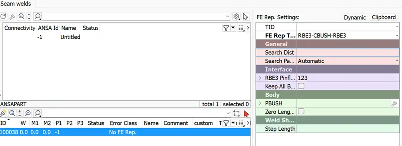
Enter the P1 and P2 PID nos and open the FE rep type and choose RB3 CBUSH RB3
Enter S = 5
Enter search distance as 10
It requires a PBUSH PID, so create a PBUSH and enter the pid number in the options
Then click realize
seamline connections
The window damper is modelled using seamlines
Go to perimeteràfeat2curve and create a curve that is parallel to the surfaces and covers the overlap area
Go to convert, select the curve and chooseseam
Go to connection manager
Select seamline
Enter the P1 and P2 PID nos and open the FE rep type and choose OVERLAP SHELL
Enter search distance as 10
Use base sheet = P2
Choose define width by angle and enter value as 45
Root shells = offset row
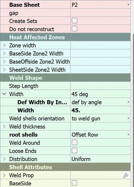
Then click realize
Mass
Go to Nastran à elements à RBE2
Use loop to select the loop and create a master node
Do this for both the loops
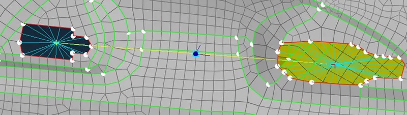
Use cog to create a mid point
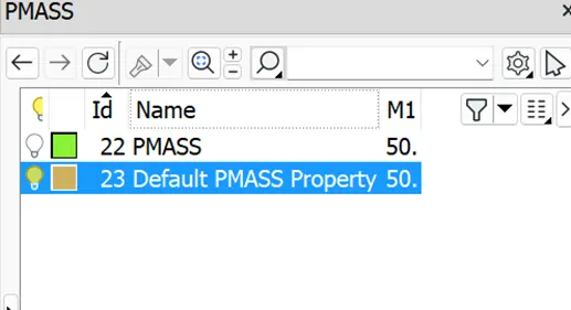
Go to elementsà CMASS1à one node
Add value as 50
Hinge connections
Go to Nastran à elements à RBE2à many nodes
Use loop to select the loop and create a master node
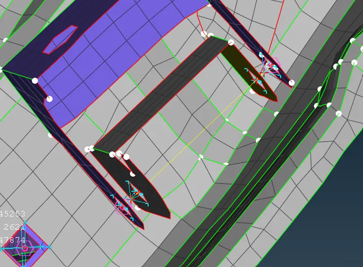
Do this at both ends
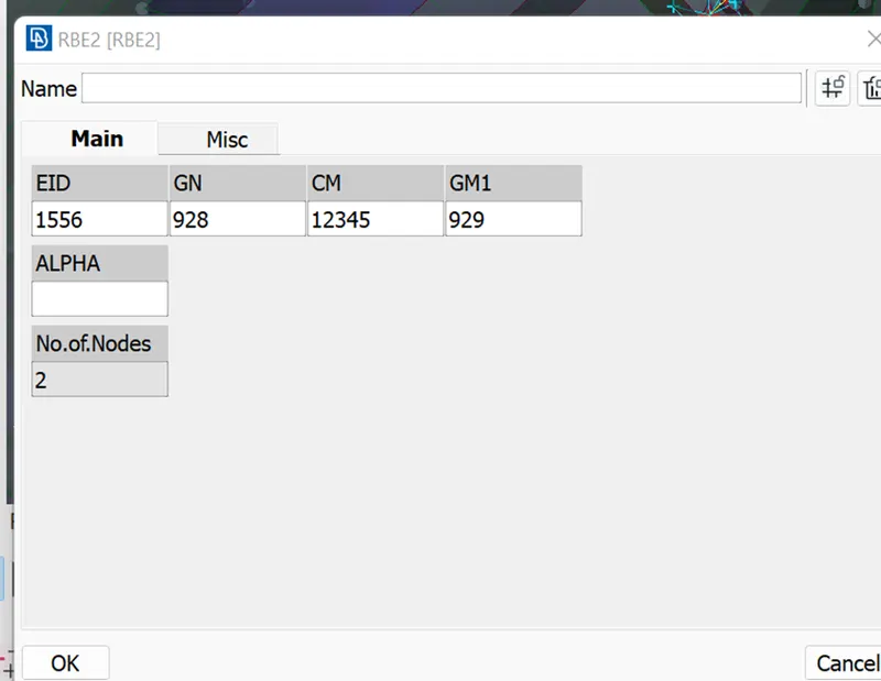
Go to Nastran à elements à RBE2à 2 nodes
Select the two nodes
Change the CM to the above shown value as the door rotates in the z direction
Check
Do the connections all over the model and to check
Isolate a PID
Click on all neighbours
Then click on invert
There should not be any pid visible in this view
The following image shows this view
Conclusion
Creating various connections like RBE2,CBUSH,RBE3 HEXA RBE3 and BOLT
Assigning mass to the model