Week -2
Simulink challenge 2
Doorbell using solenoid
Objective
Make a Simulink model of Doorbell using solenoid block with the following details:
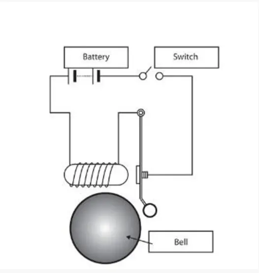
In the above arrangement, when the switch is closed the electromagnet receives electrical power from the battery and pulls the metal arm to hit the bell producing sound.
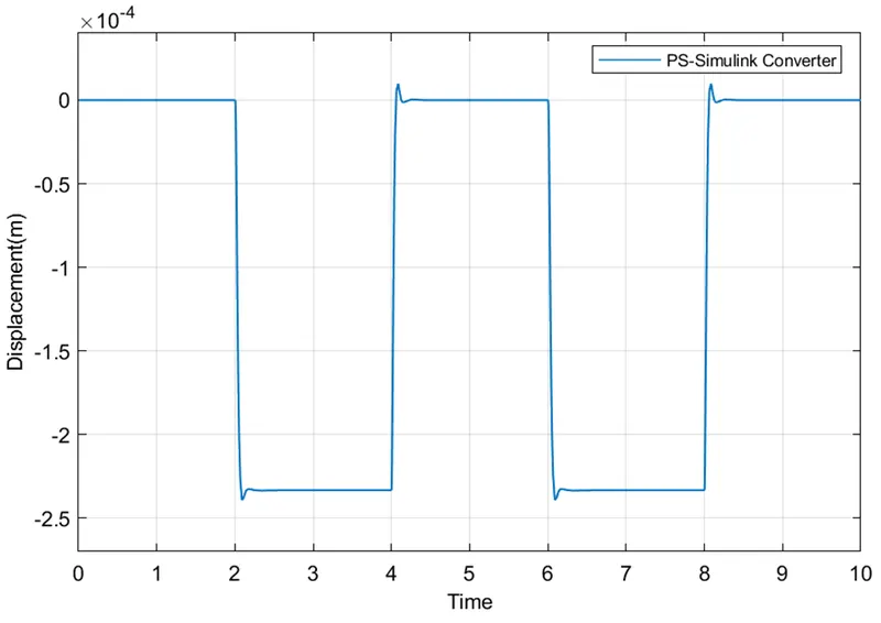
Create a situation where the switch is closed for 2 seconds and then released. Observe the physical movement of the plunger.
Working of a doorbell
The heart of a doorbell is an electromagnet. Electromagnets are coils of wire wrapped around a small piece of magnetic metal. When electricity passes through the wire, it creates a magnetic field around the wire.
When you press a doorbell button, you complete an electrical circuit that allows household electricity to flow through the doorbell's internal electromagnet. The magnetic field generated by the electromagnet is then used to power a mechanism that creates the doorbell sound.
Solenoid
A solenoid is a type of electromagnet, the purpose of which is to generate a controlled magnetic field through a coil wound into a tightly packed helix. The coil can be arranged to produce a uniform magnetic field in a volume of space when an electric current is passed through it. The term solenoid was coined in 1823 by André-Marie Ampère to designate a helical coil.
Simulink diagram
Pulse generator
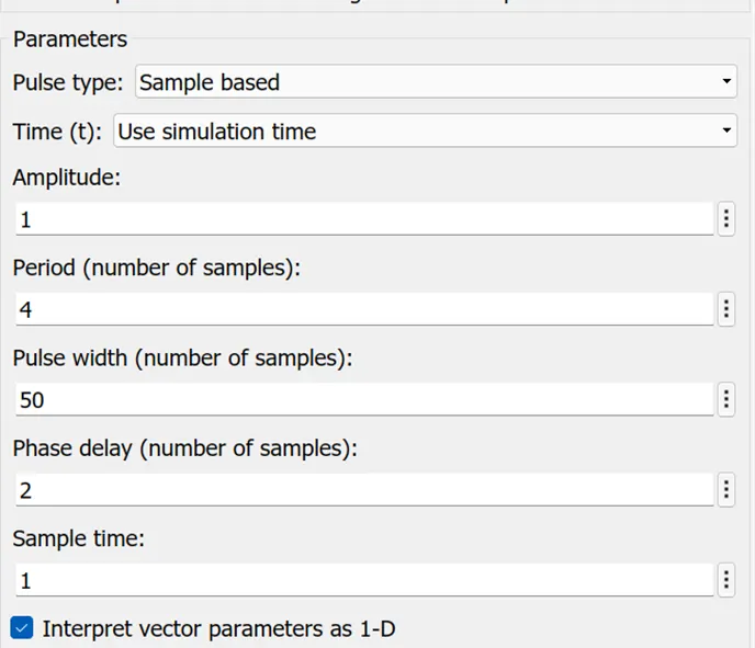
Pulse generator is used to generate a pulse of 2seconds by using following parameters
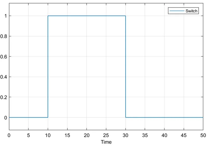
This creates a signal of

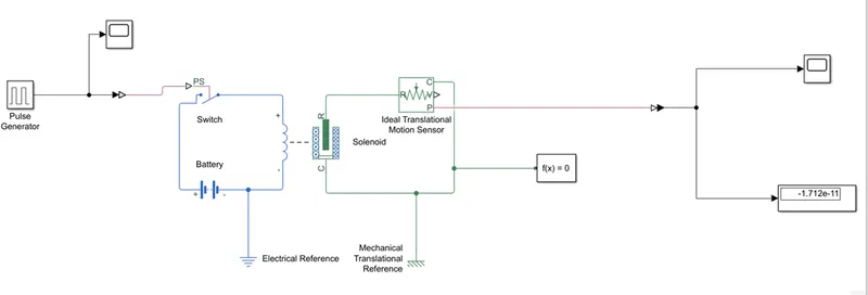
Solenoid is used as an electromagnet which converts electric current to mechanical motion
Switch is used to complete the circuit
Battery provides power supply
Ideal mechanical translational motion sensor is used to measure the displacement of the solenoid spring.
Scopes and displays are used to display the output signal
Output
Simulink challenge 2
Thermistor fan model
Objective
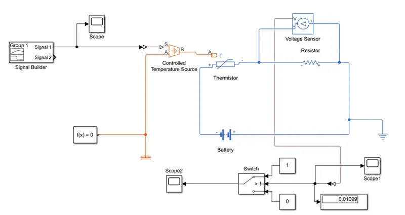
Use a thermistor to sense the temperature of a heater & turn on or turn off the fan as per the below conditions:
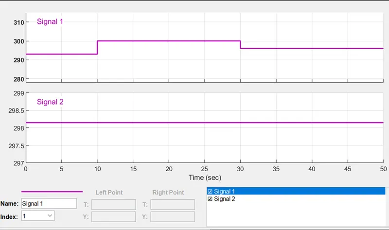
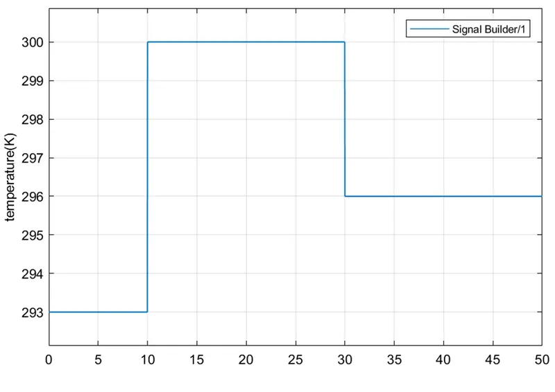
Temperature source: 20 °C from 0 to 10 seconds, 27 °C from 10 to 30 seconds, 23 °C from 30 to 50 seconds
Fan conditions: ON if the temperature above 25 °C, OFF otherwise’
Thermistor
A thermistor is a resistance thermometer, or a resistor whose resistance is dependent on temperature. The term is a combination of “thermal” and “resistor”. It is made of metallic oxides, pressed into a bead, disk, or cylindrical shape and then encapsulated with an impermeable material such as epoxy or glass.
There are two types of thermistors: Negative Temperature Coefficient (NTC) and Positive Temperature Coefficient (PTC). With an NTC thermistor, when the temperature increases, resistance decreases. Conversely, when temperature decreases, resistance increases. This type of thermistor is used the most.
Simulink model
Blocks used
Signal builder – used to create input Simulink signal
Controlled temperature source
This block represents an ideal energy source in a thermal network that can maintain a controlled temperature difference regardless of the heat flow rate. The temperature difference is set by the physical signal port S. A positive temperature difference causes the temperature at port B to be greater than the temperature at port A.
Thermistor
This block represents an NTC thermistor using the B-parameter equation.
Resistor
This is used to create a potential difference.
Voltage sensor
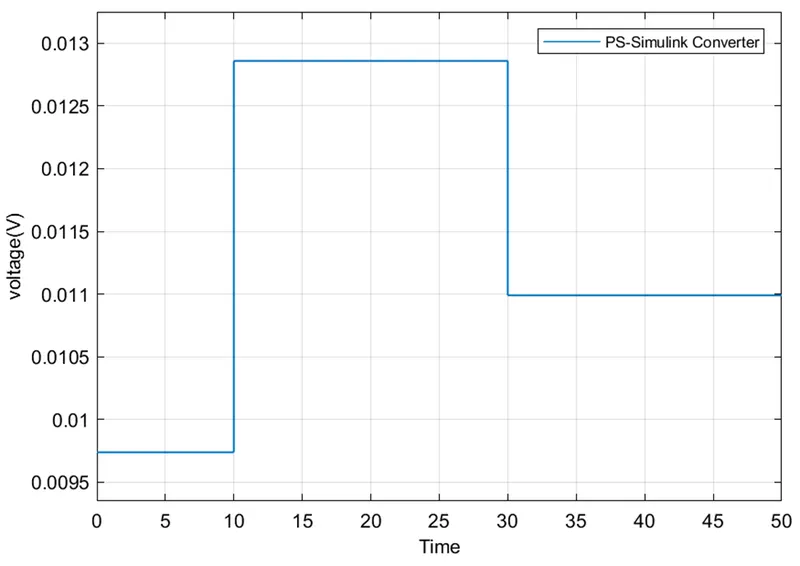
Used to measure the potential difference across the resistor
Switch
The physical signal from voltage sensor is converted to Simulink signal and the connected to a switch.
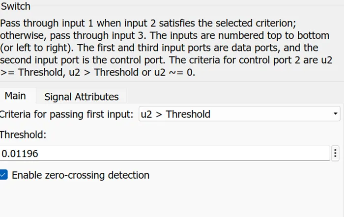
The voltage for temperature of 298.15K (25C) is calculated and is 0.01196V
This is used as threshold value for the switch.
If V>threshold then switch is ON unless switch is OFF.
Observations
Input signal
Voltage sensor signal
Output signal