Week 6 - Creating connection for Rear door
OBJECTIVE :
- Creating and applying the PID for all the parts.
- Creating and applying suitable connection whenever required.
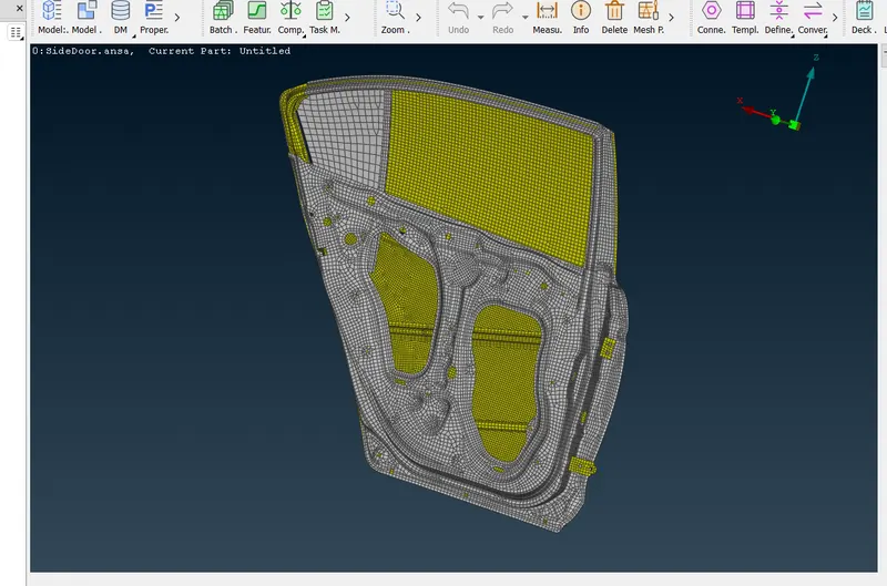
CAD Model :
Procedure :
- Rear Door model is imported and Model is checked for all parts.
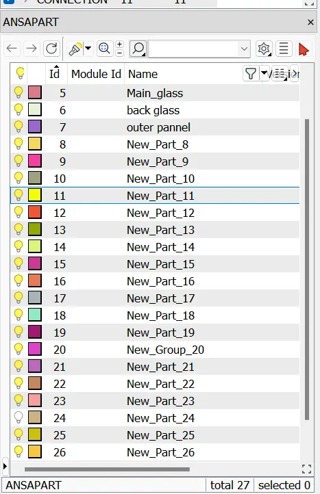
- For all the parts PID created and applied to all parts.
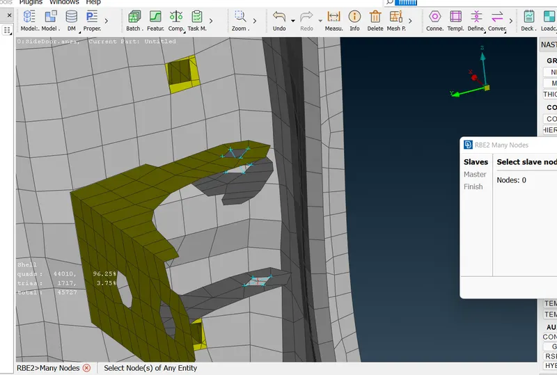
- Initially rigid connection is created using the RBE2 element at the Door hinge, with locked DOF in all direction, where door is attached with the BIW of the vehicle.
- This RBE 2 elements are called as rigid bodies as it had infinite stiffness , which means it will transfer all the load to the salave nodes uniformly irrespective of the distance of the slave nodes.
- Then using the RBE2 element with the 2 nodes RBE2 element is created with the unlocked rotational DOF about the Z axis .
- This is because , Door has to open and close only about global Z axis .
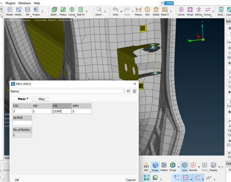
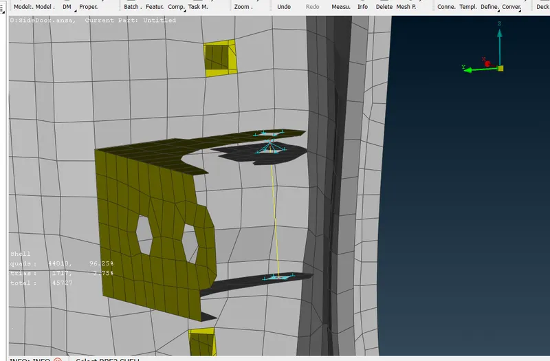
- In the same way RBE2 elements are created at another door hinge .
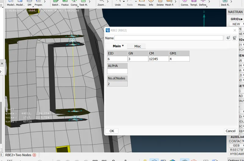
- Then the plate which is connecting the Door to the BIW of the vehicle is attached to the door with the Rigid connection as ,with DOF constrain in all direction.
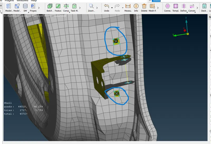
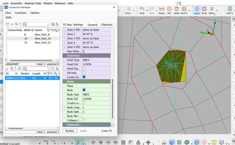
- Initially 3D point is created and then using the converter this 3D point is converted to the Bolt symbol .
- Then using the connection manager, Bolt connection is applied and realised as,
- Plate which is attached to the window glass is attached to the mechenism with the verticle plate which moves up and down when mechanism is activated.
- This plate is attached to the verticla plate with the rigid connection as,
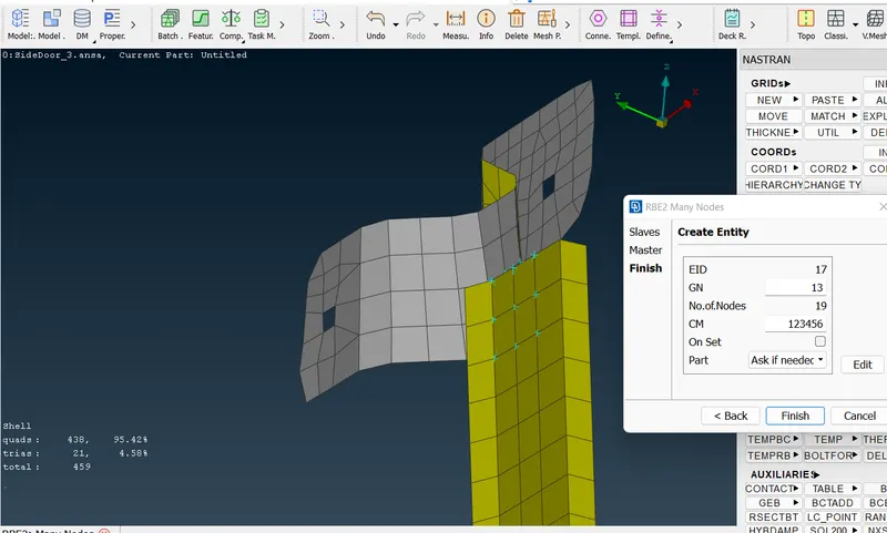
- Then this verticle plate attached with the window attched plate with the same as,
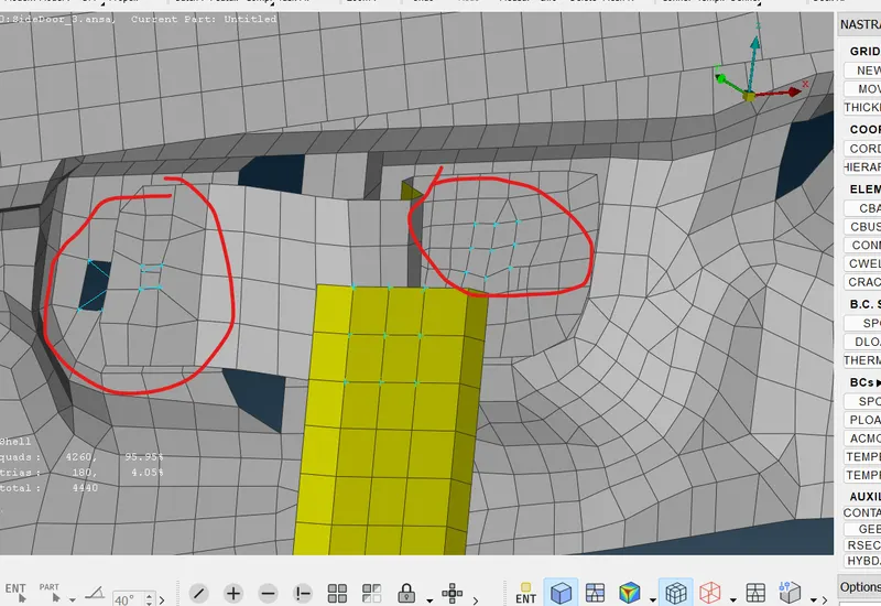
- Window glass and plate is then connected using the rigid RBE2 elements for farm connection .
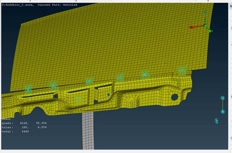
- Now for providing the connection between the window glass and the door, RBE3-CBUSH-RBE3 element is used as we cannot use the rgid connection as window glass is attached to the mechanism by which it opens and closes.
- This RBE3-CBUSH-RBE3 elements will not establis a rigid connection .
- This 1D element allows the movement of the window glass when vehicle got in crash situation.
- For creating this connection , initially curves are created.
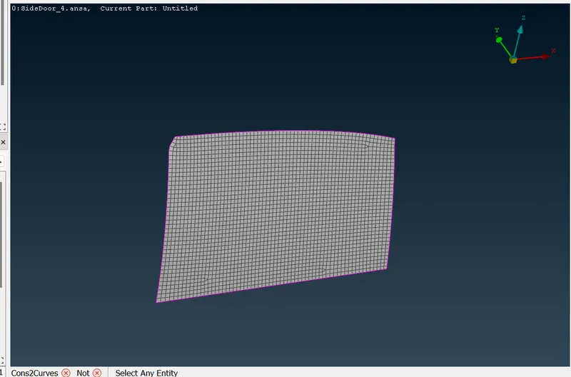
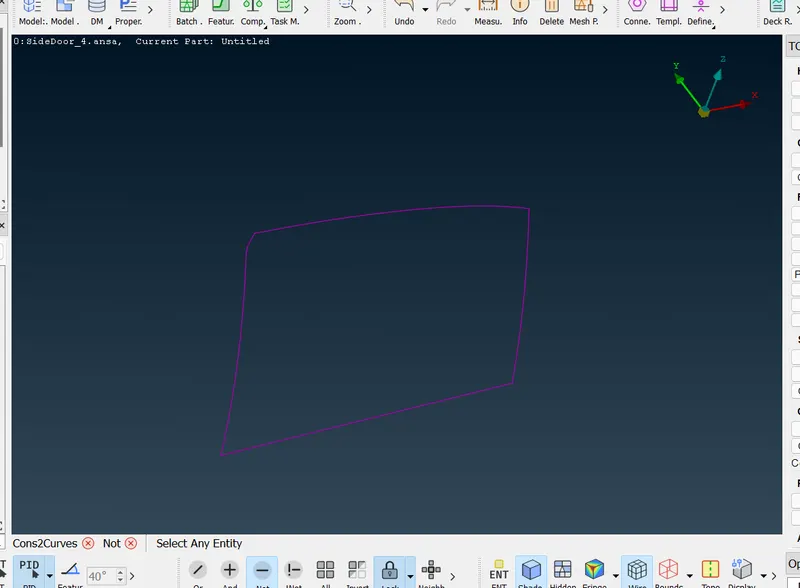
- Which are then converted in the spotlines one by one using the Converter.
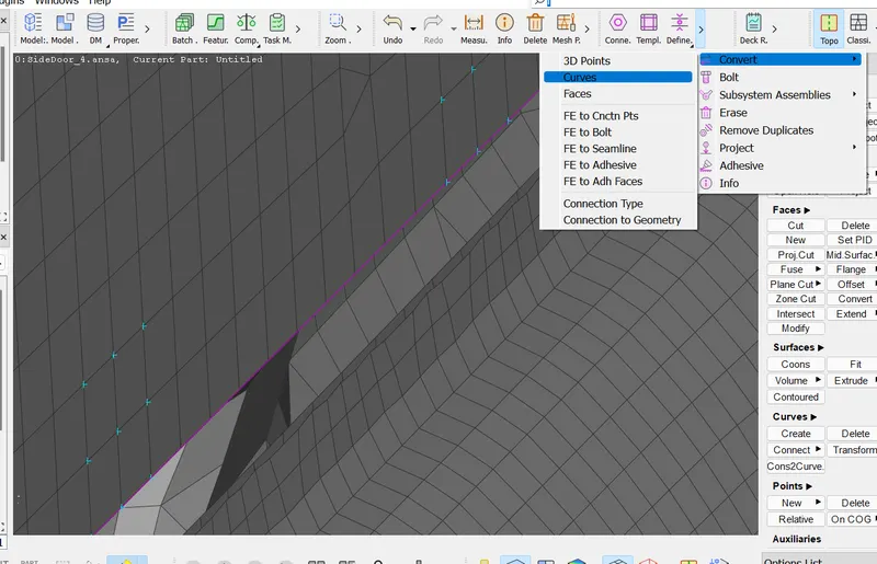
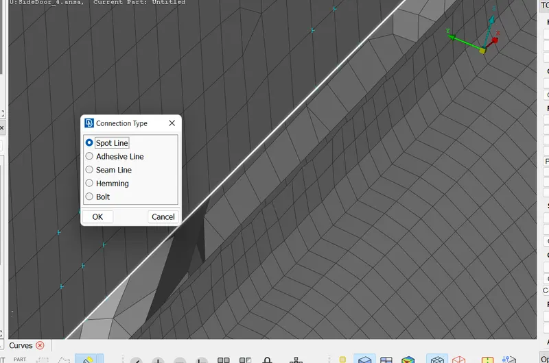
- Then this spotlines are converted into the RBE3-CBUSH-RBE3 connection with the CID as 0 .
- Hence this 1D connection will be associated with the globale cordinates system.
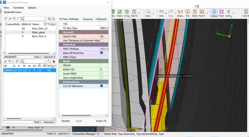
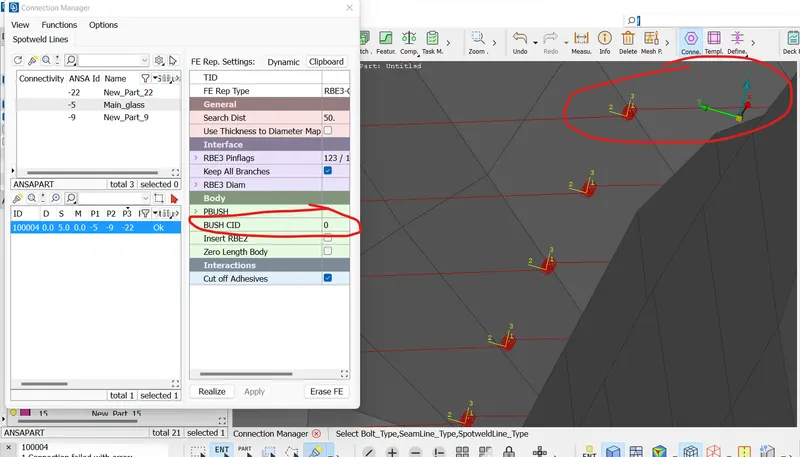
- In the same way for other side same RBE3-CBUSH-RBE3 connection is provided .
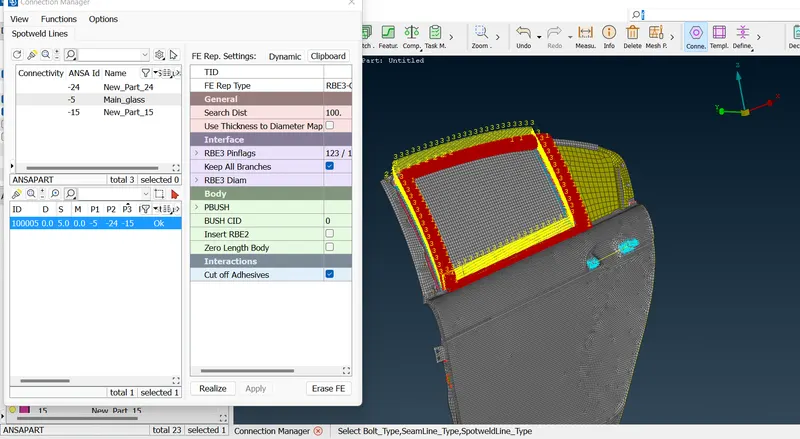
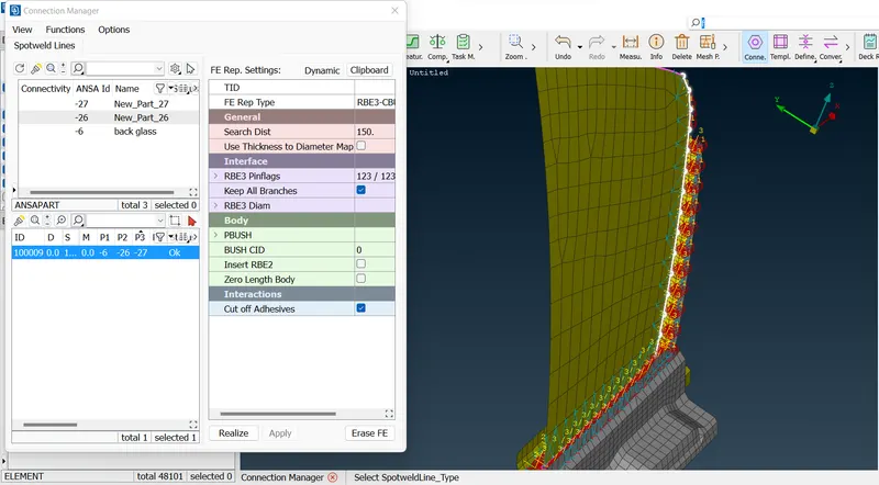
- Same procedure is used for the back side glass of the window as ,
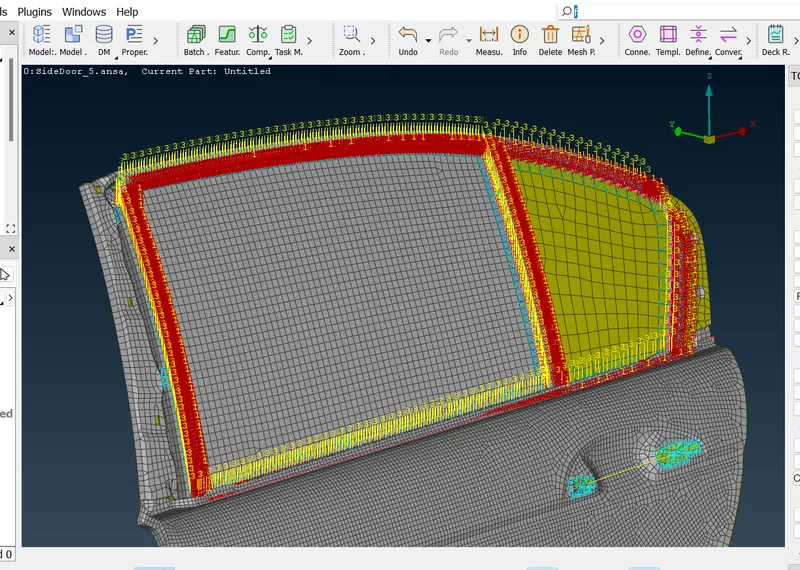
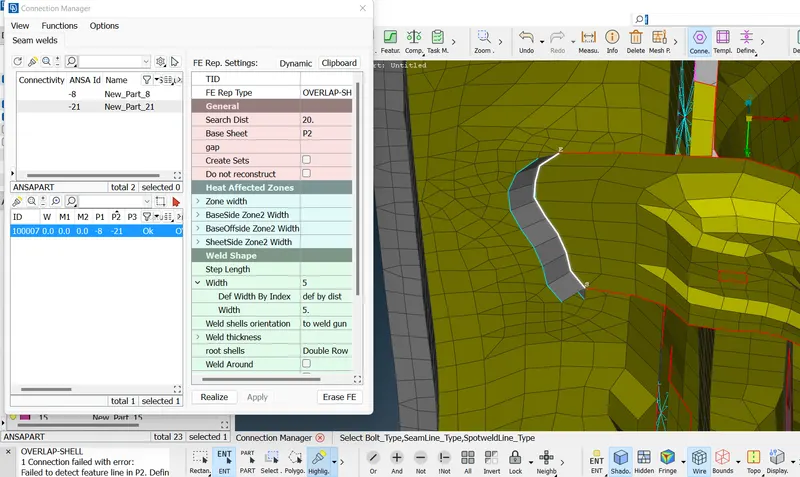
- The cross members behind the outside door panel , is connected by seam welding .
- For this connection , firstly curve is created and this curve is then converted in the seanline.
- Using connection manager , this seamline is converted to the sean welding as ,
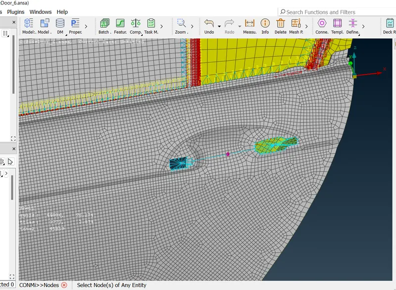
- For door open close handle connection , firstly rigid elements are created and then two node element is created for connection both of them.
- Then using the CONM2 element the mass of the handle which is about 100 gm is added in term of tonns.
Conclusions :
- For all the parts seperate PID is created and applied.
- Suitable 1D connections are created between various parts whenever required.
- For connection RBE2 , RBE3 and CONM 2elements are used.
- Final is attached below .