Week 6 - Creating connection for Rear door
Aim
To provide connections to the rear door model and to assign different PIDs.
Procedure
Step 1: import of CAD model
Files->open->select the file->click open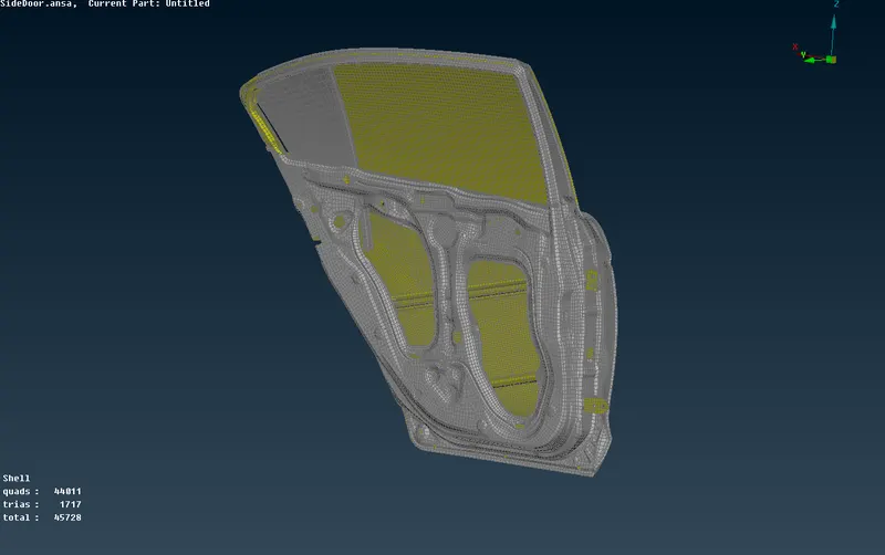
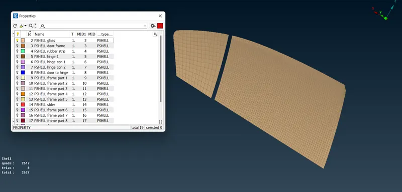
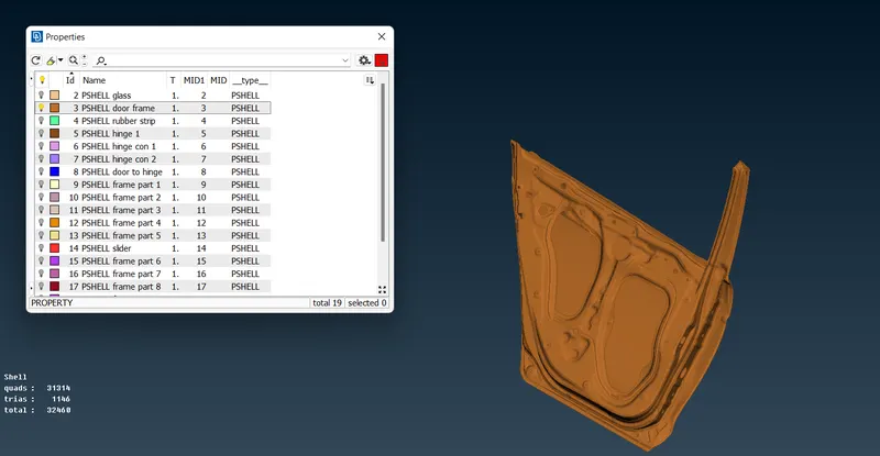
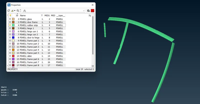
Step 2: assigning PID
Topo module->faces->set PID->select entities->click middle mouse button->new PID->select the newly created part->click ok
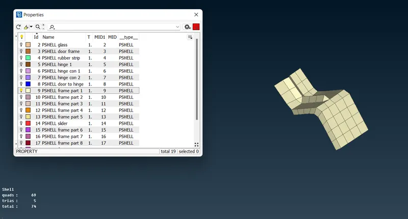
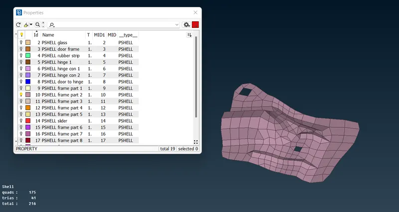
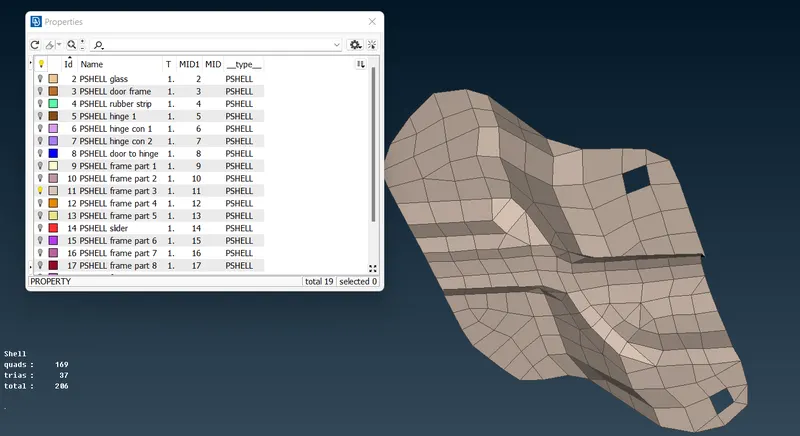
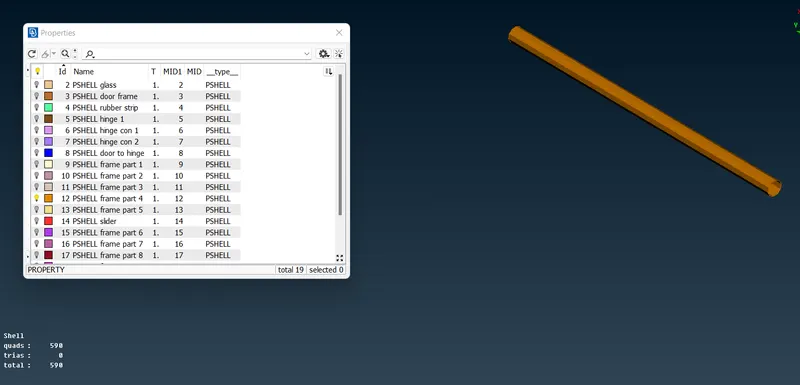
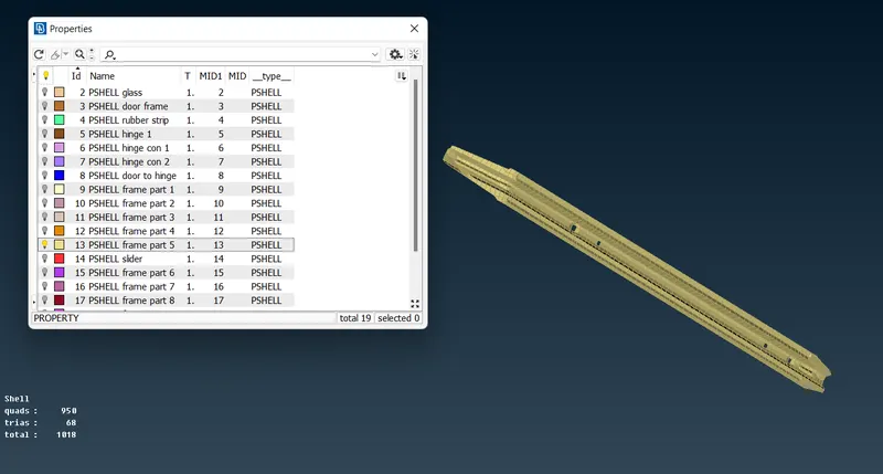
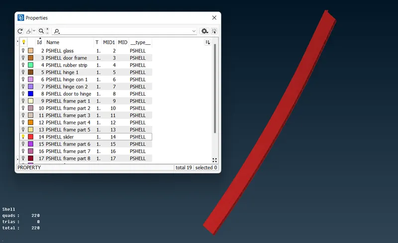
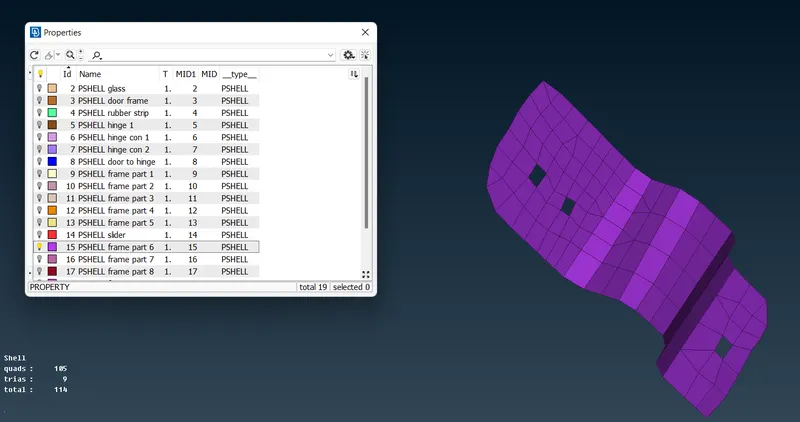
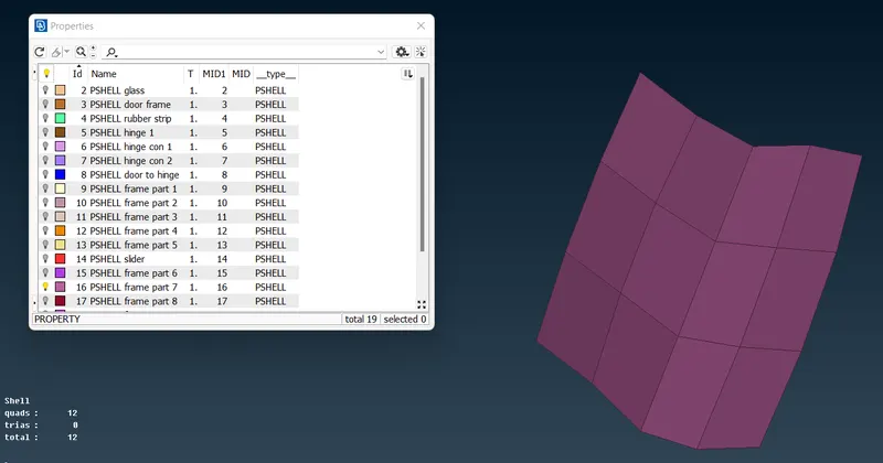
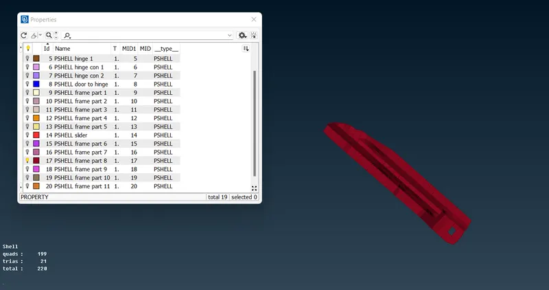
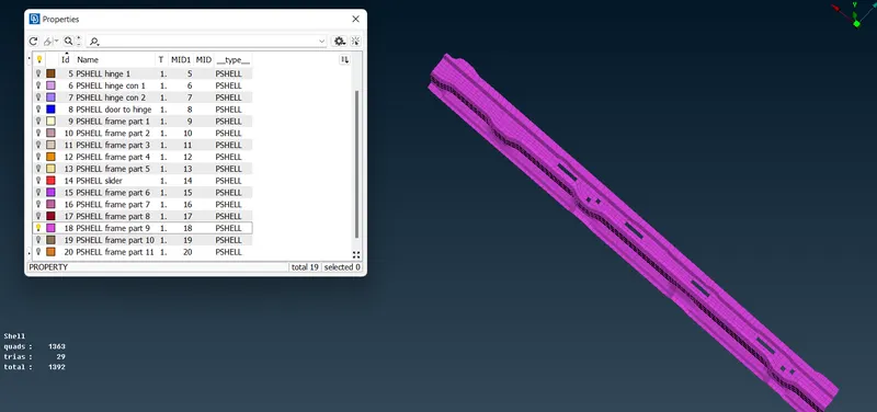
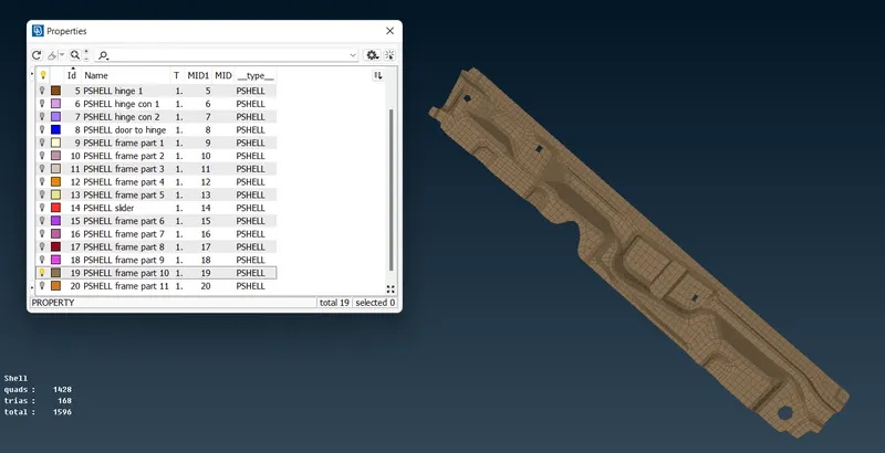
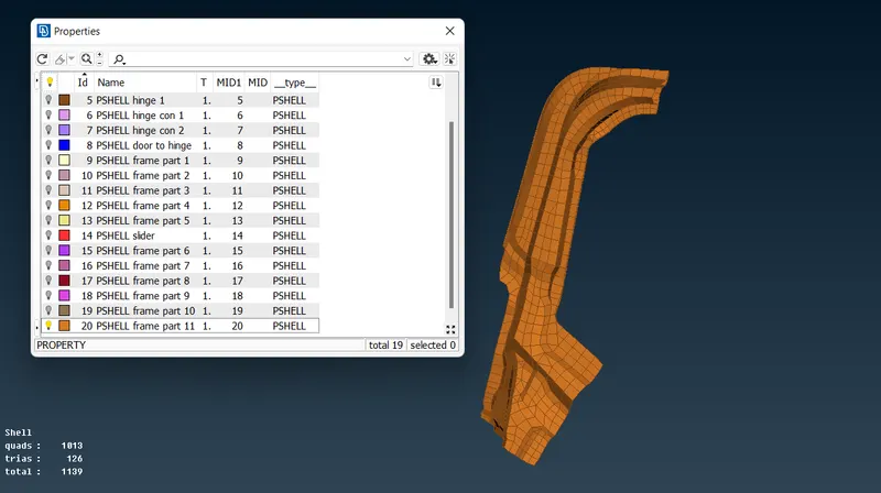
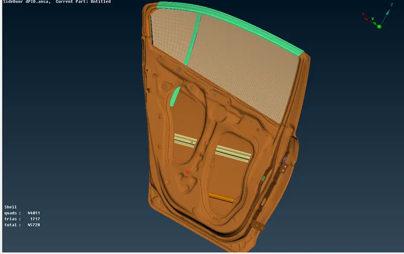
Here the given cad model is a rear door of the car where all parts are enlisted as a single PID it will make it difficult to identify parts.so, different PIDs are assigned to every part.
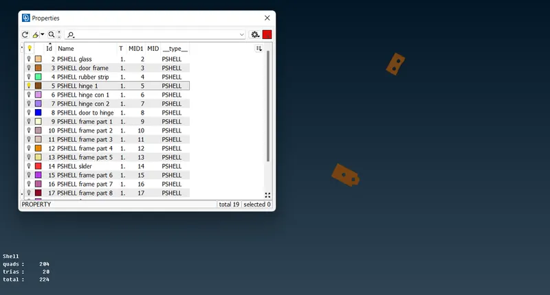
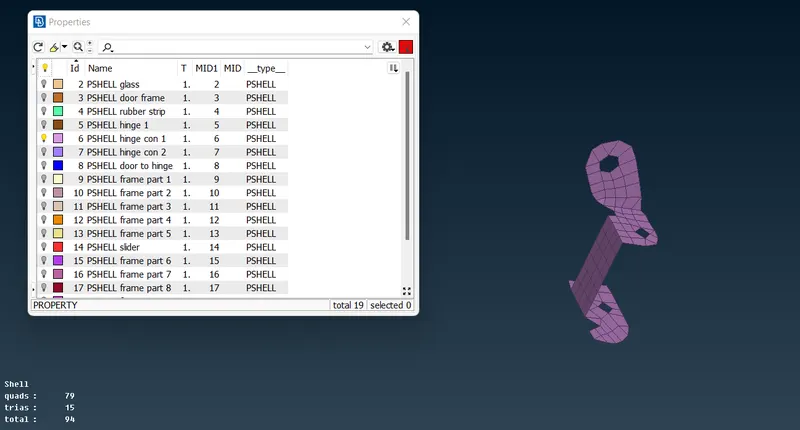
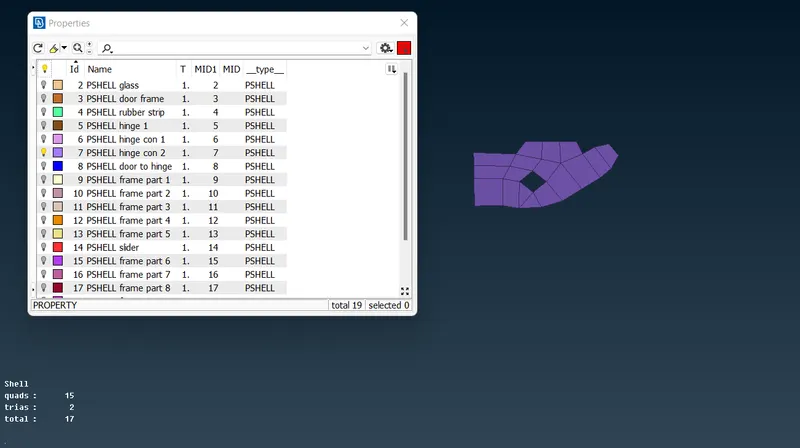
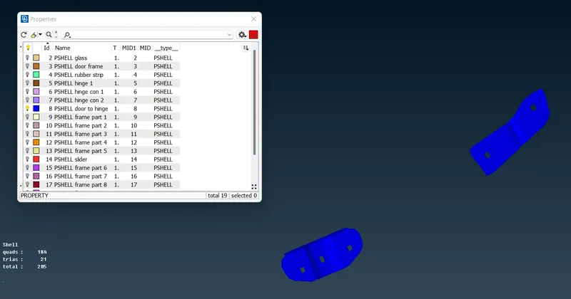
Step 3: providing connections
Connections are manually entered to specify how the parts are to be connected. It provides to reduces the complexity of the number of parts to be involved.
Rigid connection-RBE2
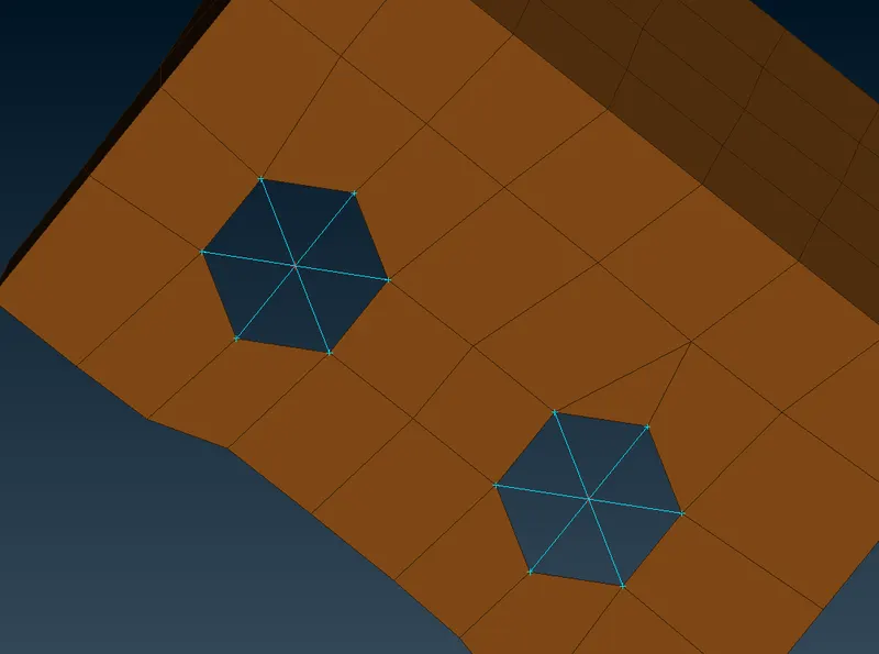
RBE2 is a kinetic coupling that created infinite stiffness to the nodes to be constrained. The independent node or master node is placed at the center of dependent nodes or slave nodes. The motion of independent node controls the motion of dependent nodes
Nastran module->element->RBE2->select entities as slaves->provide master node or the system will provide master node based on cog->click ok
Bolt connection
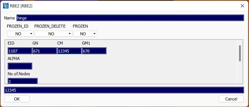
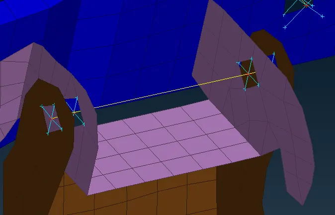
RBE2->2 nodes->select two master nodes->click
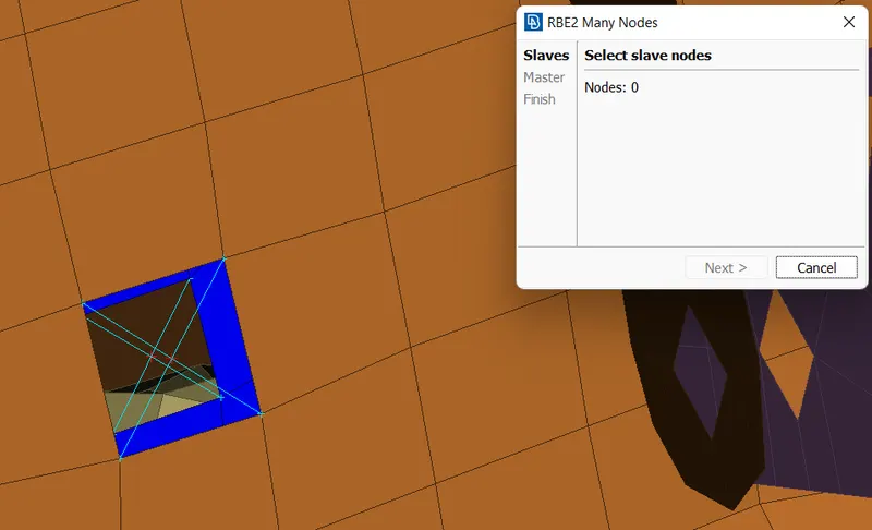
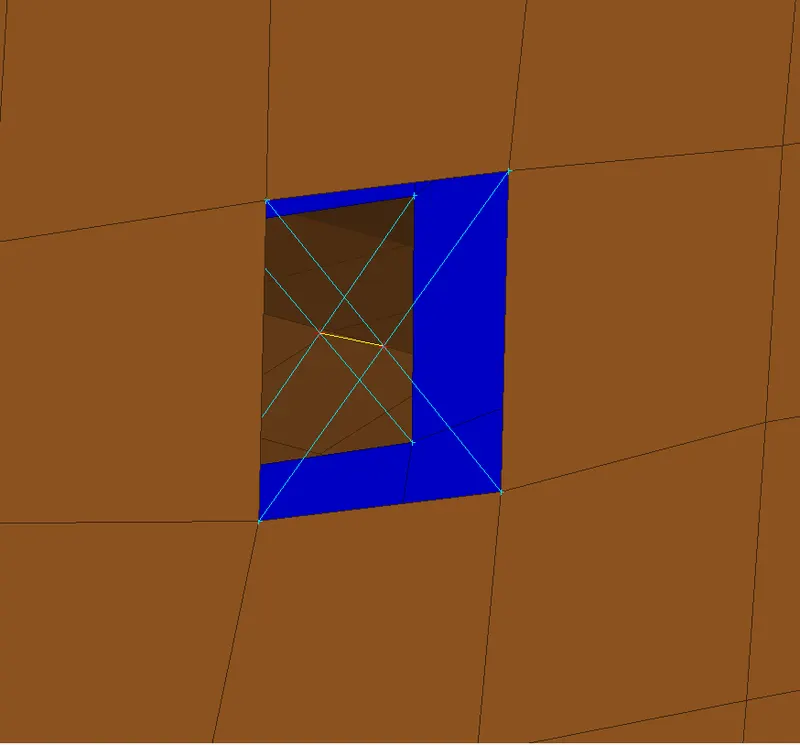
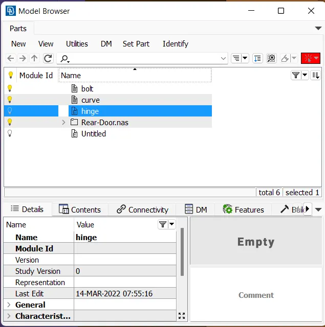
Select the part entities and set a new PID or use the existing one. It gives user advantage by reducing the parts to be used as well we know the number of bolts used in this component is different in size, diameter, mass, etc., so by providing a different part name to the connection while importing cad geometry of bolt to the specific model will automatically assign the bolts in the corresponding places where the connection employed.
Cm represents what is the degree of freedom to be locked.
In places of hinge the degree of freedom to be free in at least one rotational axis.
Here 123 represents directions in the x-axis, y-axis, and z-axis.
And 4 represents rotational motion in the x-axis
5 represents rotational motion in the y-axis
6 represents rotational motion in the z-axis
Spot weld connection
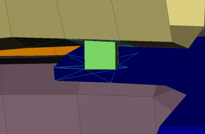
For the creation of spot weld, we need 3d point. Cog option is used to create a 3d point
Topo module->points->on COG->select entities->click middle mouse button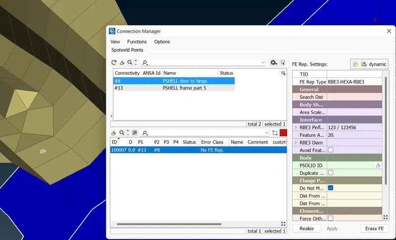
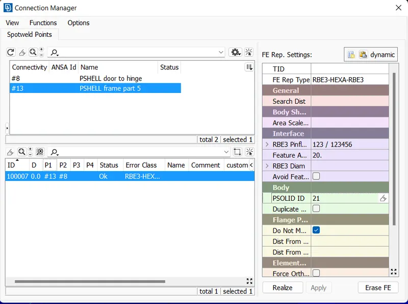
Assembly->convert->select 3d point->choose spot weld->click connection manager select
Weld connection
First, we need a curve by using the feature2curve option. The curve is needed to be converted to seamline to perform weld connection.
Connection manager->select seamline->provide FE type->give or select p1,p2,w->provide search distance->provide weld PID->click ok->click realize
c bush connection
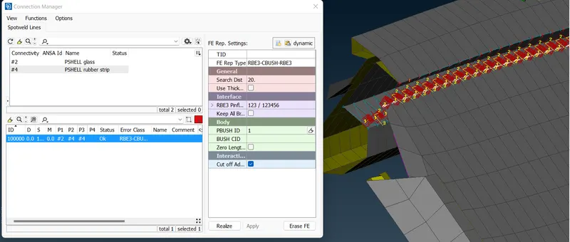
C bush is employed where sealing on moving surface involved
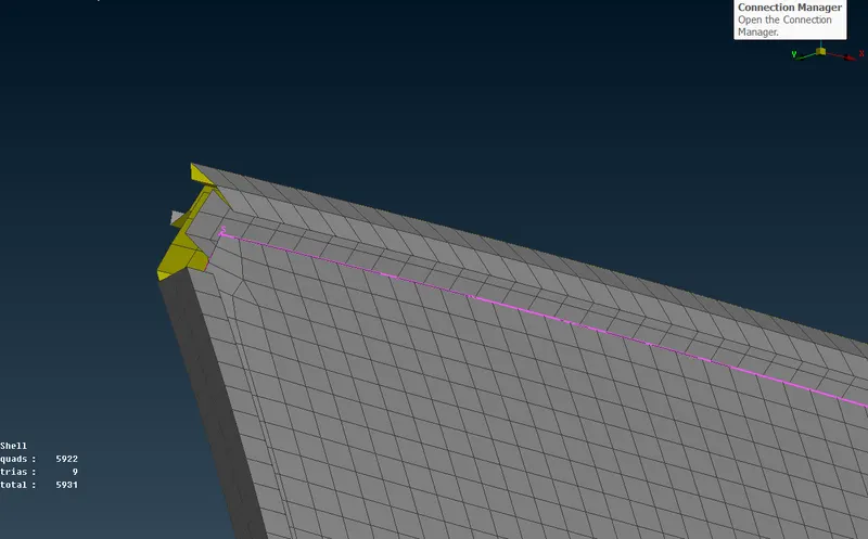
Convert features to curves using feature2curve option
Assembly module->convert->select curve->spot line->connection manager->select spot line->provide spacing value->enter PID->enter search distance->create bush pid->apply->realize.
Learning outcome
- leaned to define connection and its types
- difference between RBE2 and RBE3
- create connection PID
Conclusion
The given model rear door was provided with a different PID and connections are provided to the model.