Project 1 - 2D meshing on the instrumental Panel
Aim
To perform geometry checking for any errors and mesh with the given element quality criteria. After meshing the component the thickness has to be assigned.
Procedure
Step 1: import of CAD model
File->open->select the CAD model-> click OK
The given cad model is in the “.ansa” formate which is an ansa file. The connections of the model is already been assigned. In the case of the “.IGS” file, the connection between the surface is lost during conversion or importing the CAD file to ANSA.
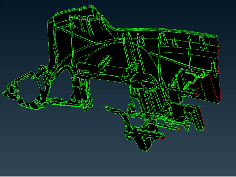
The given component is a half side of instrument panel console of a car which is usually made up of plastic, glass fiber, carbon fiber, and steel components it is used in the frontal part inside the passenger compartment it includes an airbag, air vent, instrument panel, infotainment system, etc.
Step 2: topo option
Topo module-> faces->topo->select entities->click ok
The topo option is used to provide connections between two surfaces and for resolution, the length option is used.
Mesh module->perimeter->length->select entities->enter the target length->click ok
Step 3: geometry cleanup
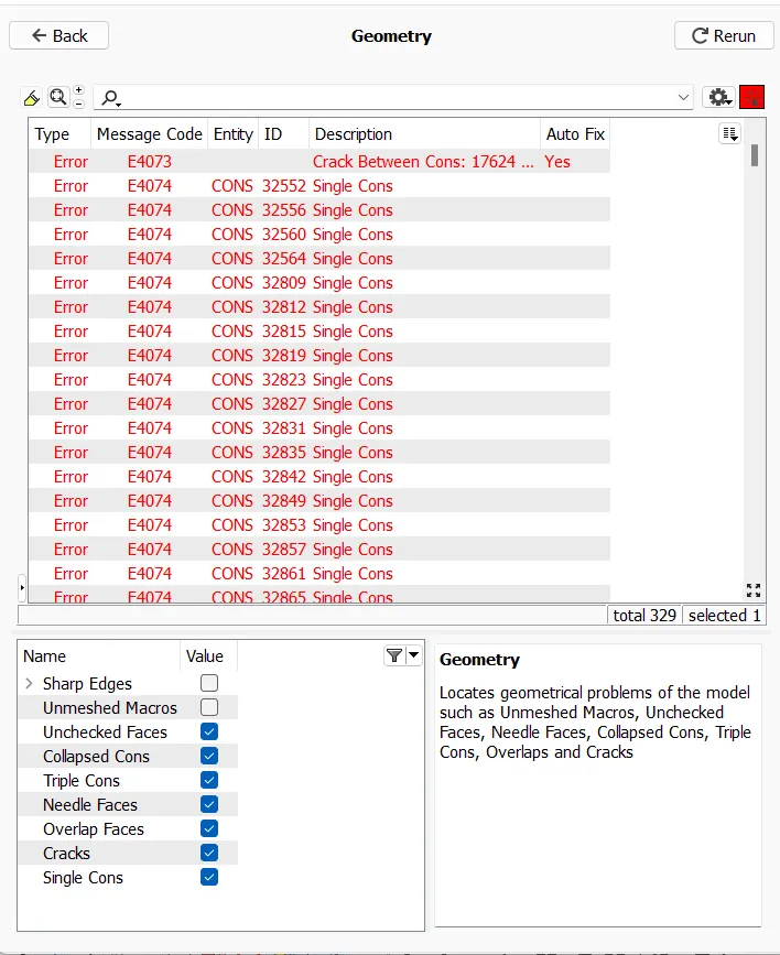
The geometry check is been performed in the parent model to have a good surface finish and to avoid unnecessary surfaces like collapsed surface, needle faces, collapsed con, etc., these parameters are been checked to get an accurate model while extracting mid surface
Since it is a half component the single cons are present where the other half has been separated. So that we can ignore the single cons and proceed with mid surface extraction
Step 4: mid surface extraction
By measuring the thickness of the component in various places it concludes that the thickness of the component is less than 6mm so it can be considered as a sheet metal part. The mid surface can be extracted to perform FEM.
Methods of mid surface extraction used
- Offset
- Middle multi
- Producing new surface by tracing curves
Offset method
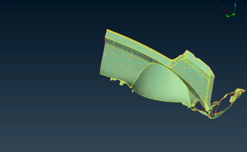
The outer console part is measured as the thickness of 0.6mm. the least feature area is been selected for creating offset because the features like ribs and button cap are needed to be captured separately for capturing feature area in the FE model
The offset method is been used where the thickness of entities is been uniform across the component.
Topo module->faces->offset->faces->select faces to be offset->enter the distance->click ok
Middle multi-method
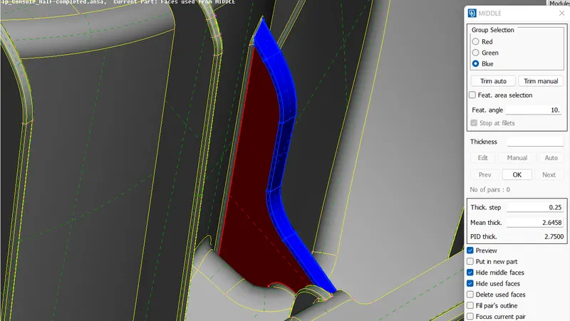
This method of extracting mid surface is been used where the thickness of the component is non-uniform.
Topo module->face->middle->multi->select green faces->select red faces(opposite to green faces)->select blue faces(generally thickness or perpendicular to red and green faces)->unckeck delete original faces->click ok
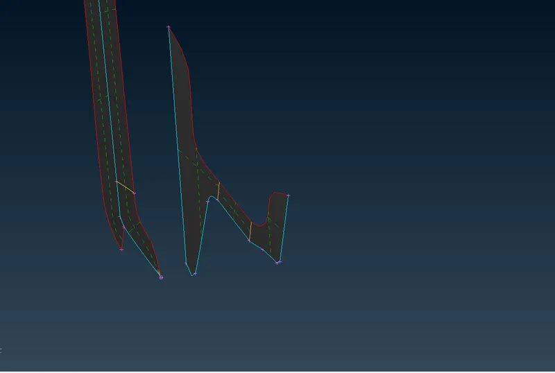
Producing new faces using curve
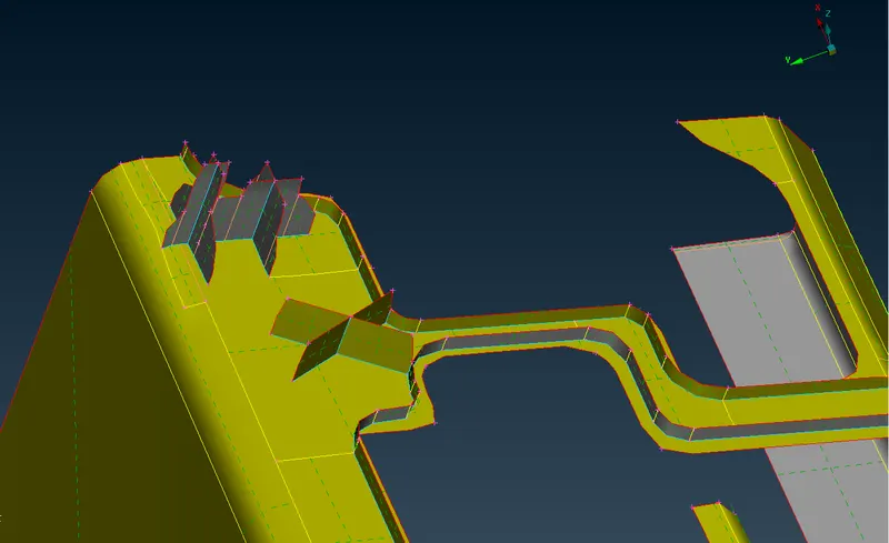
The outline of the button neck is been traced using create curve option
Topo module->curve->create->select 3d point->click middle mouse button
The curve can be created using hot points to be more accurate to the original model
Topo module->faces->new ->select cons and curves->click ok
The new surface has been created to represent the button necks
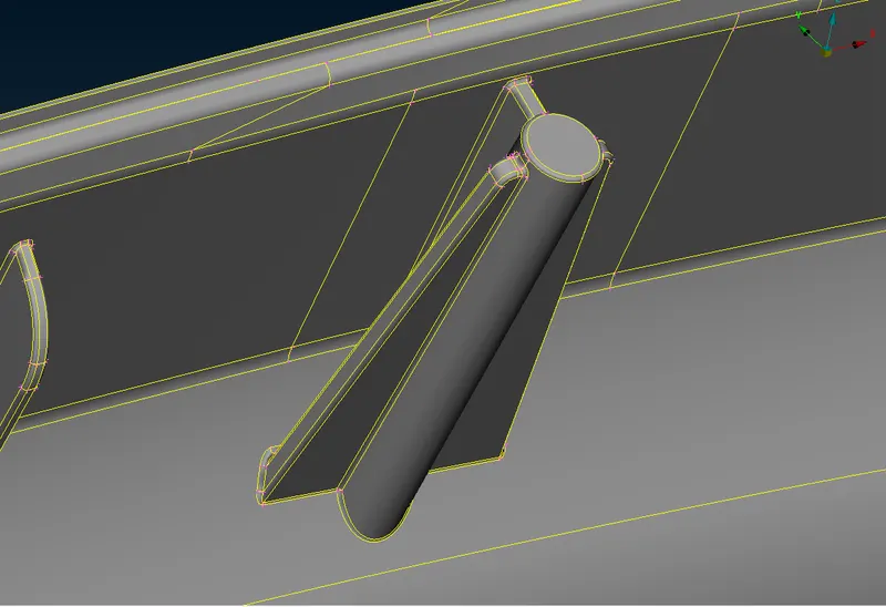
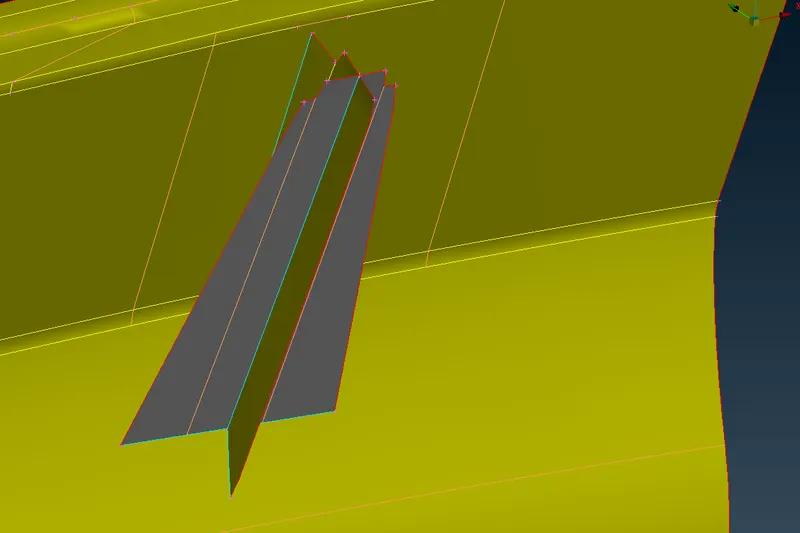
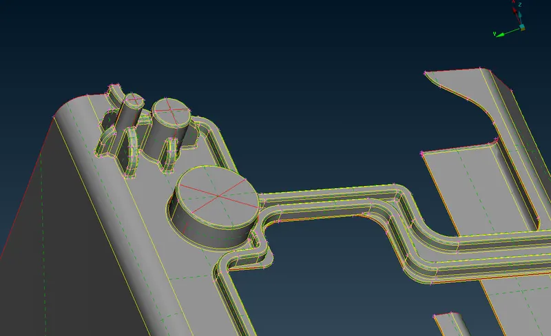
Step 5: providing connections
The options like intersecting and extending is been used to provide connections between the components to represent the parent geometry
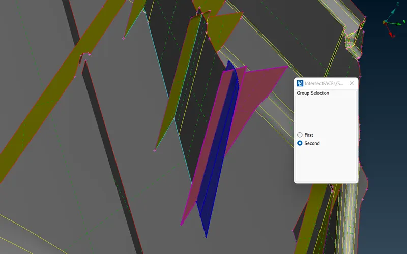
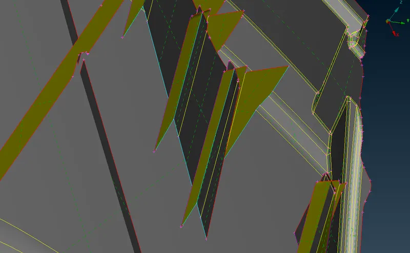
Topo module->faces->intersect->select first group and second group->click ok->delete the unwanted faces and keep the necessary faces->click stop
The intersect option is used to provide the connection between two perpendicular surfaces that are cross-connected and extend option is used to extend the face to the perpendicular surface(which is not in contact)
Topo module->faces->extend->select single cons needed to be extended->select the faces to be extended->click middle mouse button or enter
Step 6: batch meshing
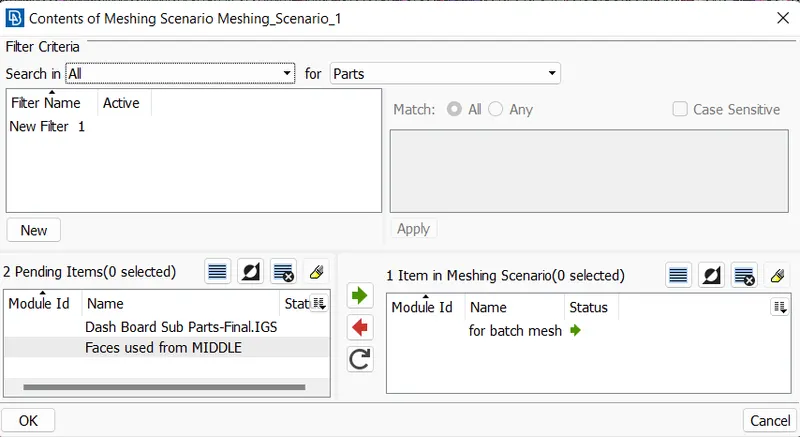
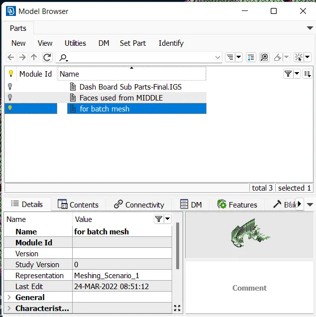
For performing batch mesh, a new part in a model browser is been created.
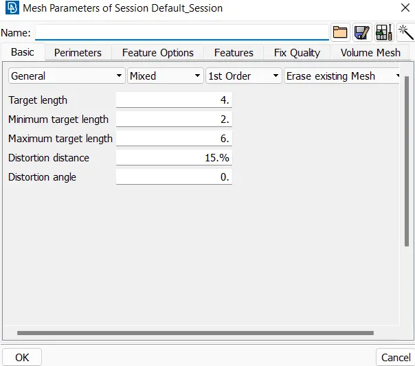
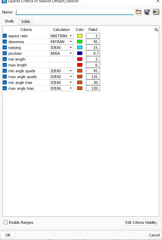
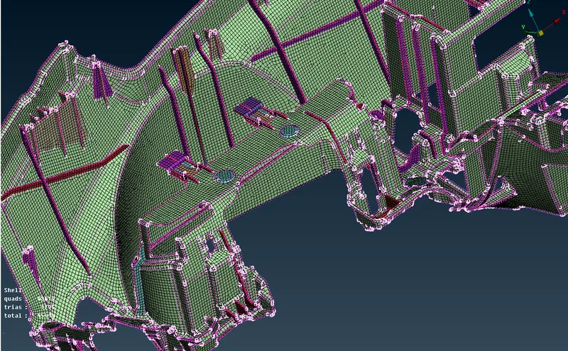
Batch mesh->new meshing scenario->select contents->enter mesh parameters->enter quality criteria->click run
The meshed model contains off elements and tria touching feature lines and single cons or free edges
To have good mesh flow the mesh model is been edited using split, paste, swap, and join operations to avoid off elements, tria facing each other, tria lying on feature area, etc.,
Step 7: set PID and thickness
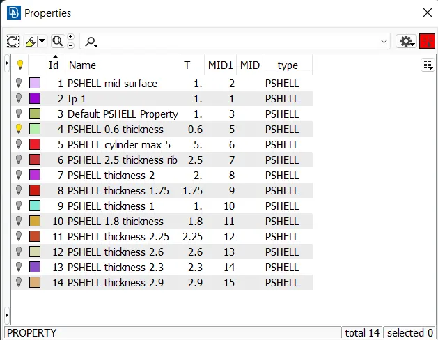
A new PID (part id) is been assigned as per their thickness to the parent geometry
Topo module->faces->set PID->select entities->click ok->assign new PSHELL->enter thickness->click ok
Step 8: draw shell as solid
Quality criteria->presentation parameters->elements->draw shell as solid->click apply-> click ok
The shell element is been converted into a solid element using draw shell as solid
Learning outcome
- Extraction off the mid surface
- Assigning PID
- Providing connections
- How to draw shell as solid
Conclusion
The given dashboard model is checked for geometry checks and the mid surface is been extracted. The given model is been meshed according to the given quality criteria and the drawn shell as solid according to the assigned thickness.