Week- 5 - Solid meshing
Aim
To check for geometrical errors and mesh the surface with 2D element criteria for the rear view mirror component.
Procedure
Step 1: import of cad model
File->open->select the model->press open
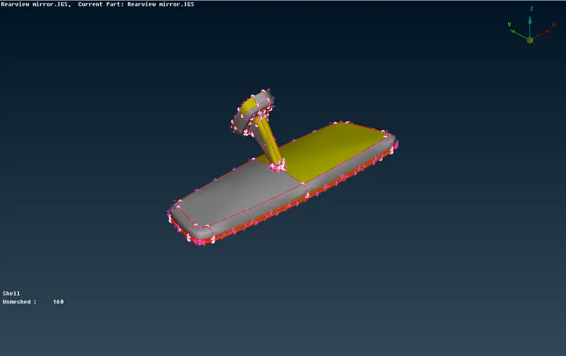
Step 2: topo cleanup
The given model is in IGS formate so the model which has been imported into the ansa GUI does not represent any connections. To bring back connections topo option is used
Topo module->faces->topo->select all entities->press middle mouse click
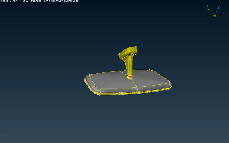
Step 3: geometry cleanup
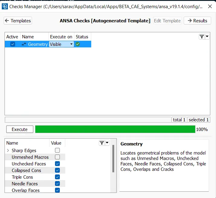
Tools->Check manager->geometry->click on checks to be executed->execute
The checks are
- Unchecked faces
- Collapsed cons
- Triple cons
- Needle faces
- Overlap faces
- Cracks
- Single con
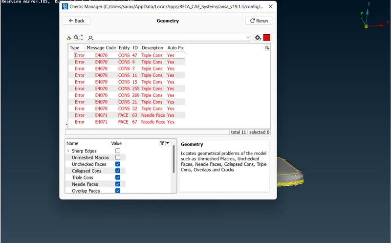
In the rearview model, it shows some errors regarding triple cons and needle face with message codes E4070 and E4071 respectively. Some of the errors can be automatically fixed by using the auto-fix option
Select all the message code->click right click->press fix->re-run the checks.
The status shows OK. We can proceed with meshing
Step 4: providing resolution
To improve the resolution of the CAD geometry length option is used
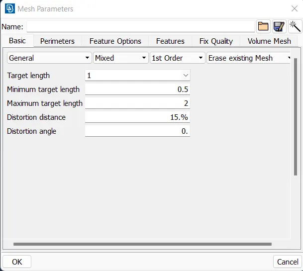
Mesh module->perimeters->length->select all entities->provide length as target length->press ok
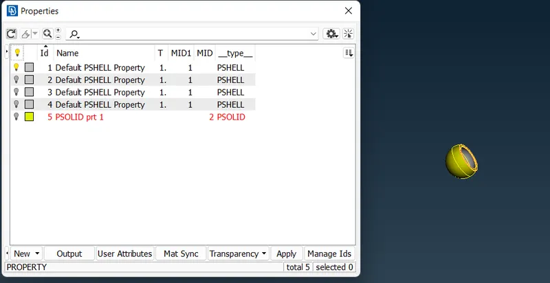
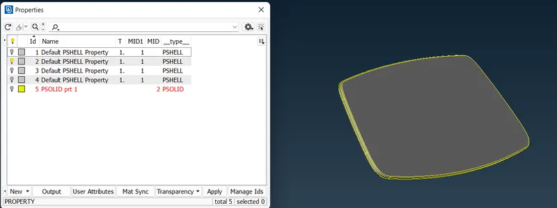
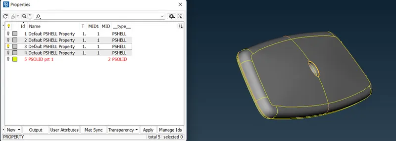
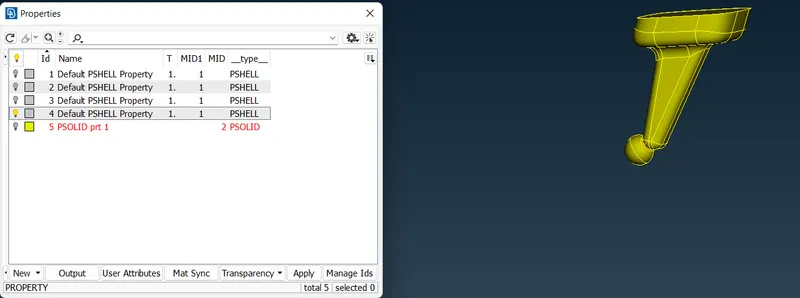
Step 5: set PID
Defining different PID to every part can be very useful
Step 6: providing quality criteria
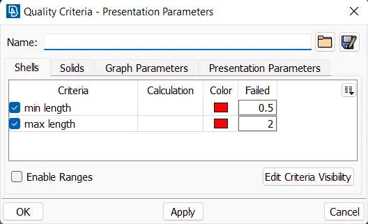
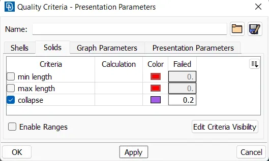
The given element quality criteria are entered in mesh parameter and quality parameter as followed
Step 7: shell meshing
In surface or shell meshing tria elements were used to capture the curves and it is easy to provide volume as tetra elements. In shell meshing we are using normal tria for flat surfaces and ortho tria in curved surfaces to match the surface accurately
Mesh module->mesh generation->best->select entities->click enter or middle mouse click
If some elements fail for given quality criteria reconstruction option can be used to mesh the selected surface to match the quality
Mesh module->shell mesh->reconstruct->select the entities failing for quality parameters->click middle mouse click->click run->click ok
Step 8: definition volume
The part needs to be defined in define volume before the creation of 3d mesh elements
Volume module->volumes->define->select entities->click middle mouse click->enter part name->click ok
Step 9: the creation of 3d elements
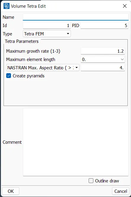
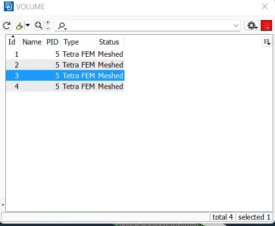
Volume module->volumes->list->select part to be meshed->click edit-> select type as TETRA FEM->click ok->click remesh-> click ok
Step 10: repair of 3d elements
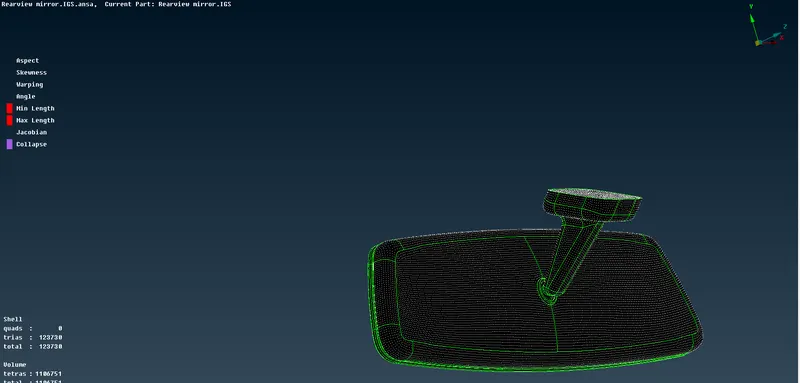
Some elements fail for collapse parameter for repairing the volume elements fix quality option is used
Volume module->improve->fix quality-> select off elements->click run->click ok
Learning outcome
- Types of elements in 3d meshing
- Defining volume
- Creation of 3d elements
- Repair of 3d elements
Conclusion
The given rearview mirror model is been checked for geometry quality and created tetra mesh concerning quality criteria