Week 6 - Creating connection for Rear door
AIM:
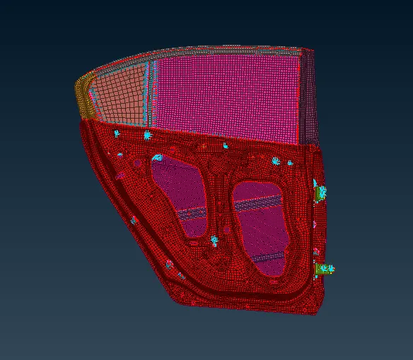
Create and Apply different PIDs for different components and assign the sutiable connection of given rear door.
Given Model:
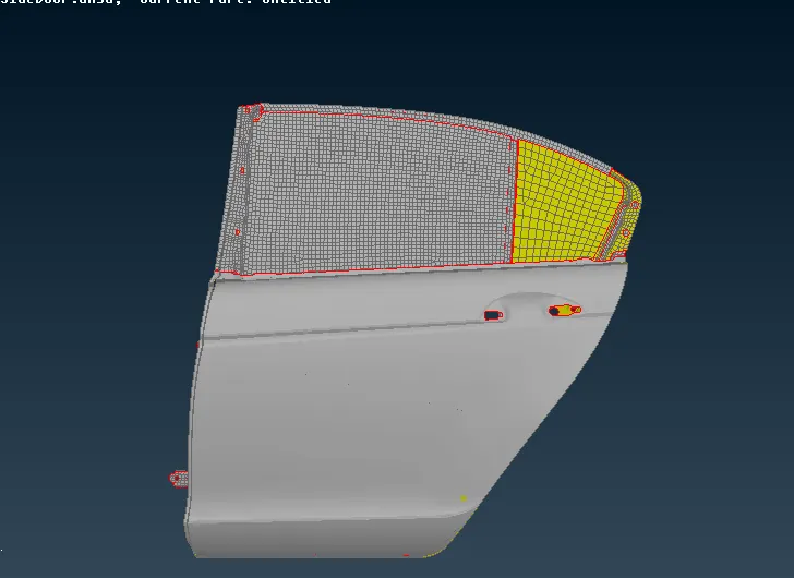
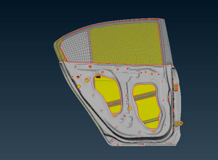
Procedure:
¬ First separate all the parts and give PID to all the components.
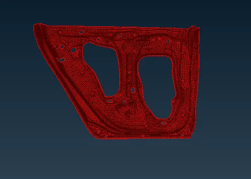
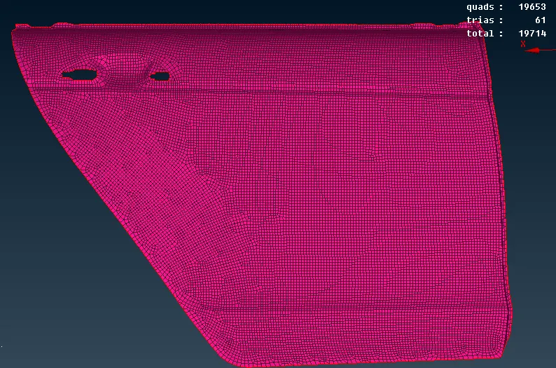
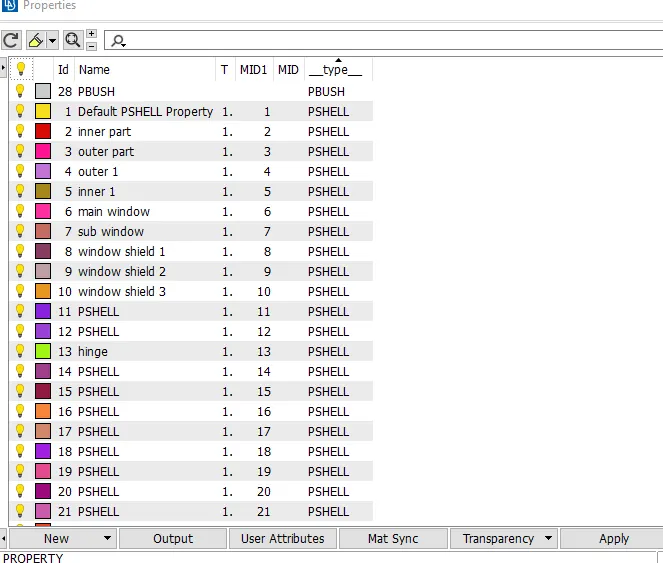
¬ Create PID for all componemnts.
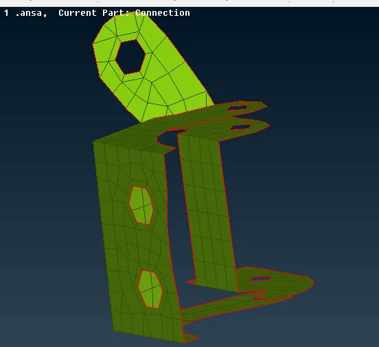
¬ Then start Bolt and RBE2 connection using NASTRAN Deck for Hinge support
¬ first go to TOPO-points-onCOG select the option and click bolt area.
¬Afterthat go for Assembly select convert click the cog and convert into bolt symbol.
¬ Then select connection option click bolt symbol and widow open p1,p2 are selected,then choose dynamic and select bolt and choose zones as in/out option after apply and realize its done.
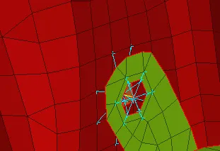
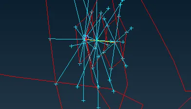
¬After that go nastran deck select REB2 two node option connect the master nodes it to be connect and give bolt stemp.
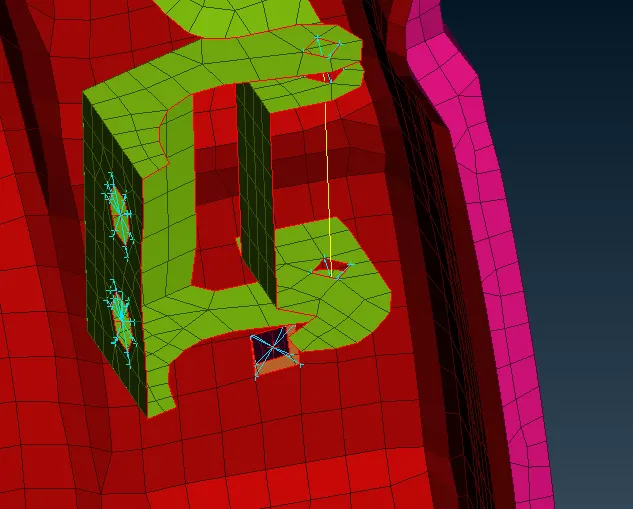
¬ Now create many nodes REB2 connection in hinge areas, Then go to RBE2 option in nastran deck, select RBE2 option and choose loop option and done the RBE2 connection to all bolt area and repeat the process to full hinge support.
¬Now go to natsran deck select RBE2-two node option connect master nodes and give leave Z rotation or 6 th degree of freedom.
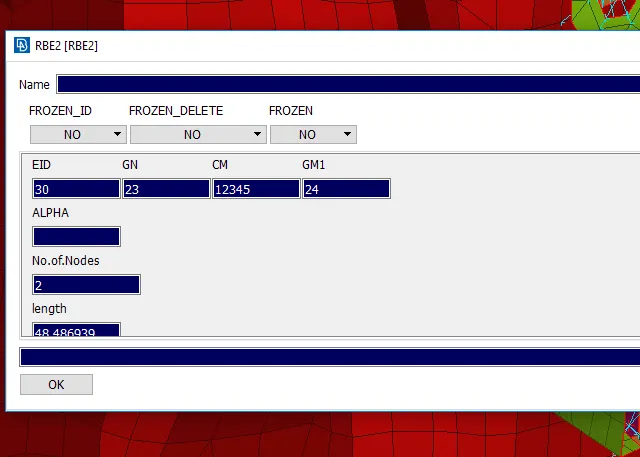
¬ Release 6th degree of freedom reason to door should open on z.
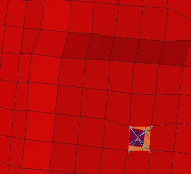
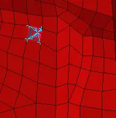
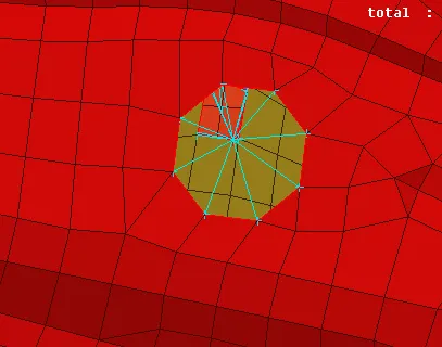
¬ Using RBE2 option and connect all the bolt and cluster area
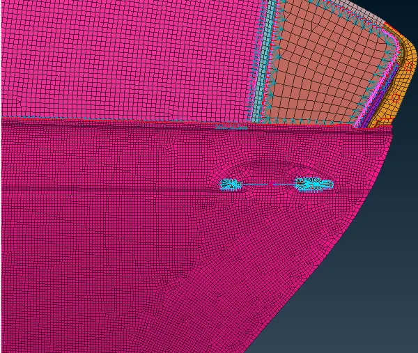
¬ Now connection to the door handle , first connect the hole using RBE2 option and connect the two hole area
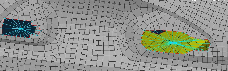
¬ After connect the two master nodes and give one master node , then give the mass value for the handle , so go to nastran deck- CONMI-CONM2-Nodes, select the master node give ok new window open give mass value as 100 garm and its converted into tonne.
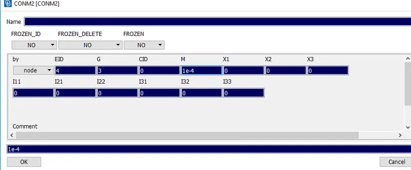
¬ Its done.
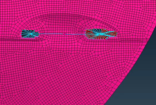
¬ now going to spot weld to some area
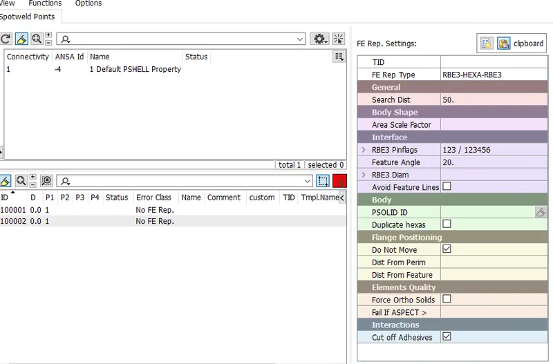
¬ First create onCOg to the going to weld area and go to assembly and convert to 3d points and select spot line option and click connect option and then create p1 , p2 selet and complete the spot weld.
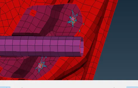
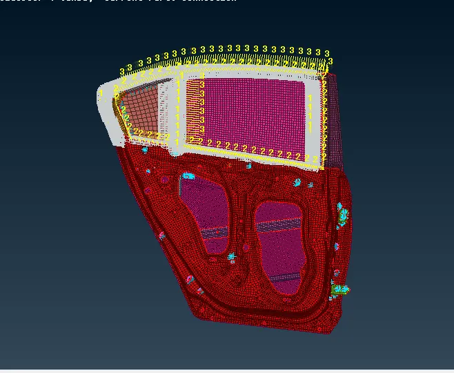
¬ Connection for Windows
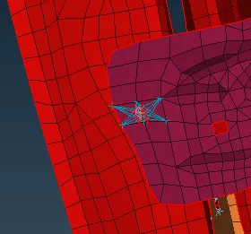
¬ Now create curve around the perimeter.
¬ convert them into spot lines
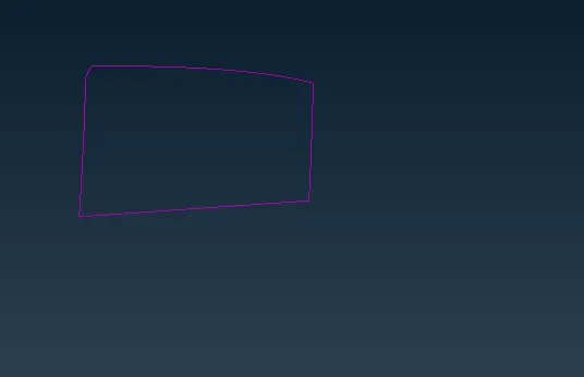
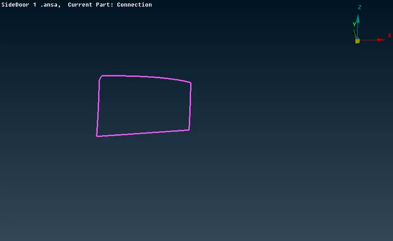
¬ select the lines after connection manager RBE3-CBUSH-RBE3 is used to represent window connection because windows are connected.
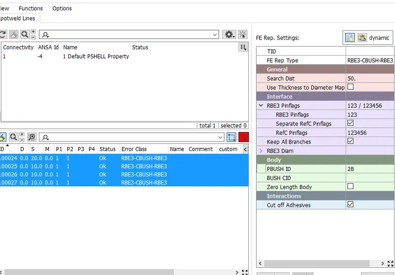
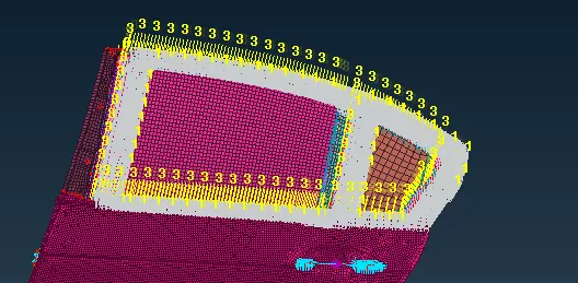
¬Assign part for connection.
¬Repeat for another window.
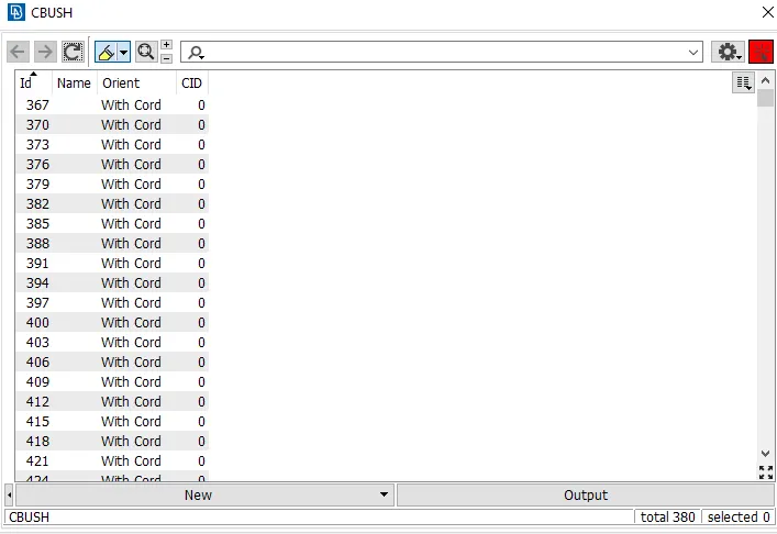
¬Change the co-ordinate to 0 in CBUSH properties so it gets globally aligned towards one direction .
Leaning outcomes:
¬ How to convert the points and curves into connecting lines and points using convert and connection manager tool.
¬ Learn how to assign property and certian values to the connection tools.
¬ Leaarn how to create RBE2 elements using nodes in NAstran deck.
Conclusion:
¬ Created separate the PID for all the components and suitable connection deployed as per requirements for the given rear door model.