Week 6 - Creating connection for Rear door
CONNECTIONS FOR REAR SIDE DOOR
AIM: In this given Rear side door FE model, the combined PID of model need to assign with individual PID's andthe respective connection need to deployed on the model.
METHODOLOGY:
- Assigning the individual PID's for every element.
- Deploying the appropriate connections at respective areas.
THEORY: The rear sidedoor is a complex sub system of the car. In an automobile having doors consists of lot of design elements inside the door sub system. For simmulation and design purpose the engineers should consider alot of elements in this subsystem, for simulation we consider only their presence of the elements n the design but not their functionality or their mechanism. In an automobile doors there are alot of moving elements like side glass window, latch, hinges door handles etc. The physical representation of these mechanism are required to generate the accurate simulation. In ANSA connections are used to represent aand rigidise the particular part where a bolt, welding, mating surface were present. the degree of freedom of the subsystem or particular element in the system were also considered accordingly. Due to having different method for connecting different elements in ANSA also we can't deploy a single kind of connections for every mating suface, appropriate connections must be made based on the type of connection between the two or more surfaces. In real life situations the engineer is instructed with connections requirement and he/she should follow accordingly.
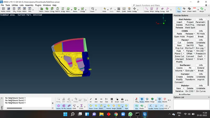
PROCEDURE: After getting the FE model of rear side door into ANSA, because we have the combined PID of ful door we need to seperate the every individual part and assign their respective PID's.
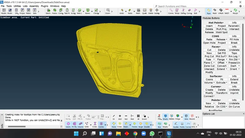
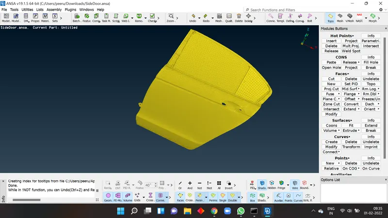
- Assighhning the individual PID's for every element:
For assigning the individual PID's goto setPID >> select faces>> now window select he particular part and by left click there will be pid section and by right click one should select the NEW option for creating the new indiviual PID for the selected element.
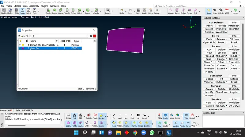
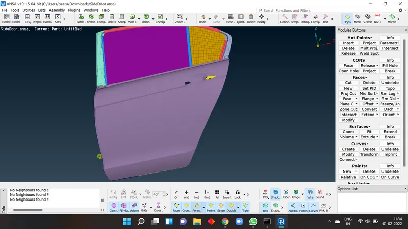
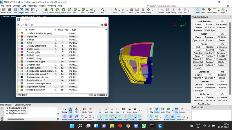
after assigning the PID's we need to deploy the connections as required, In this challenge we concentrate only on mating surfaces glass window only.
- Deploying respective connections in the system:
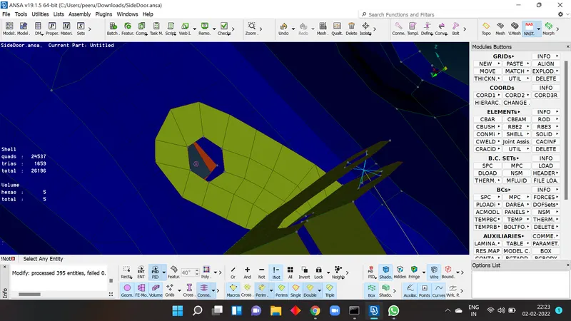
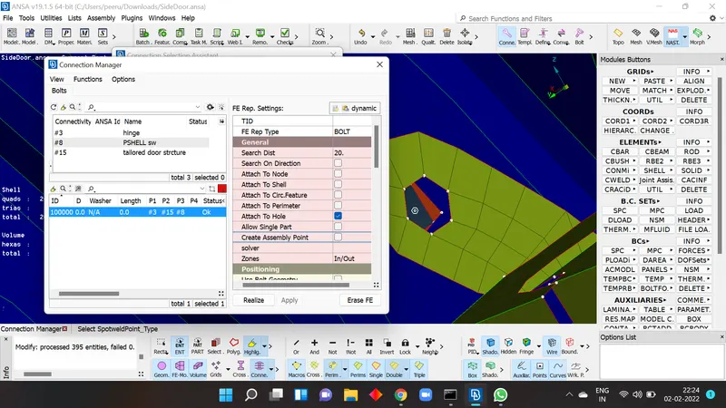
Bolt connection: A bolt connection can be deployed using RBE2 option in NASTRAN deck module. If no. of blots on same plane is more we prefer this method to generate the bulk connections at one shot
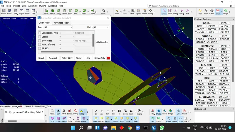
In topo module >> in points select on COG >> select the hole area where bolt connection need to be made.>> now on right side conner select the convert >> 3d point >> now select the created cog point, upon pressing enter one can convert the COG point to bolt representation. now select the CONNECTIONS on right top conner , now select bolt representation>> enter> select FE representation type as bolt>> now assign respective PID a p1 and p2 >> after giving search dist.>> select zones as required ( IN/OUT , INNER, IN/OUT X ) and give apply and realize the connection.
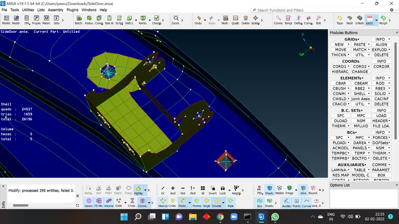
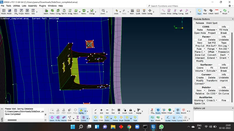
Hinge connection: It was an noral RBE2 connection but instead of rigidising the total axis we take consideration of rotational movement of door, which will happen at the hinge of the door. so, we won't restrict that particular axis of degree of freedom.
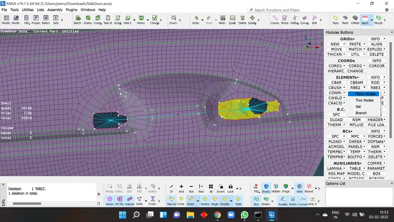
on deploying the RBE2 connectio on both holes of the hinge we will connect these 2 connections with a two node RBE2 at their respective master nodes and wont ristrict the axis of rotation by not entering the respective no. at DOF column.
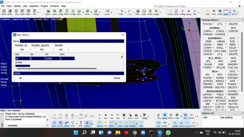
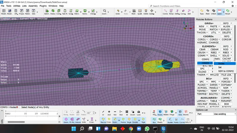
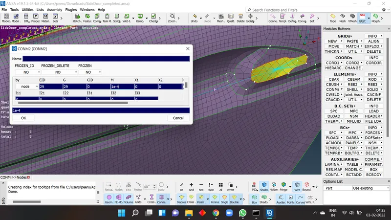
door handle connection: it is a normal RBE2 connection we select the nodes on both holes and create the seperate connections and now we connect both master nodes using same RBE2 ,there will be third master node will be generated at the center of both master nodes. because of there is no fea representation for handle we mimic these connections for representation of handle. For that we need to assign the mass for the connection. for assigning mass goto nastran >> elements> conmi> conmi2>nodes> select the node and assign the mass of the handle there .mass should always be added in tonnes, always convert the mass units to tonnes and add the value
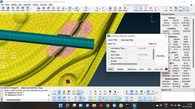
Spot weld connections: usually these connections are deployed based on data of weld representation in CAD model but we didnt have cad data where to deploy which kind of weld in this model. so, if there are two mating surfaces without any other connections like bolt, we use the spot weld to create a rigid connection between two mating elements.
For this, create ON COG point on one surface use >convert>>3d point> select the COG> convert to spot weld>>select the connections> select the weld representation>assign p1, p2 > select FE representation type as RBE3- HEXA-RBE3 > After giving the search dist. >select RBE3 pinflag > ristrict all DOF (123456)> create new PSOLID id > now apply and realize the spot weld.
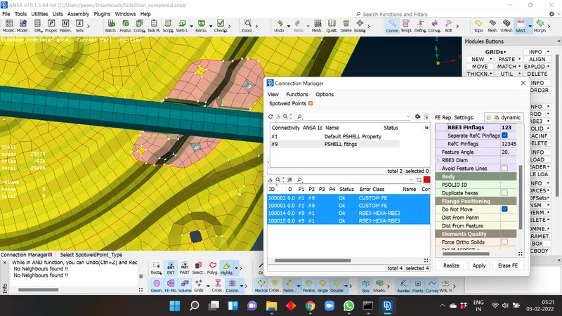
cbush connections: These kind of connection were deployed on windows to adjecent parts where the weather strips are present in actual model. These elasstic strip will hold the glass in place and keep the inner cabin of automobile free from external elements also make the cabin leak proof.
To begin, the perimeter of the glass is used and converted into curve, for that goto mesh module>> perimeters> feat2curve and select the perimeter and convert them to curves.usuallly in physical automobiles the weather strip on bottom side of the glass is placed on both sides for better support and hald the glass rigid on the remaing 3 sides of glass weather strip is placed on out side to make the product cost efficient. so, for that bottom side of the glass we need another spot line for that we use this bottom curve, use transform option > select the bottom curve > give the direction and distance that you want to copy the curve to. now turn off the FE and convert the curves using the convert option and convert these curves to spotlines. convert the curves to spot lines individually to avoid the grouping.
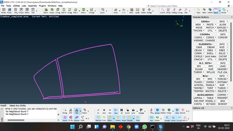
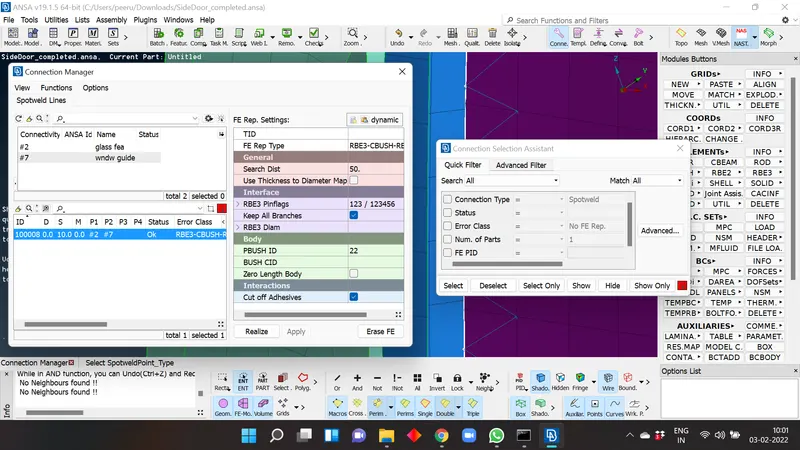
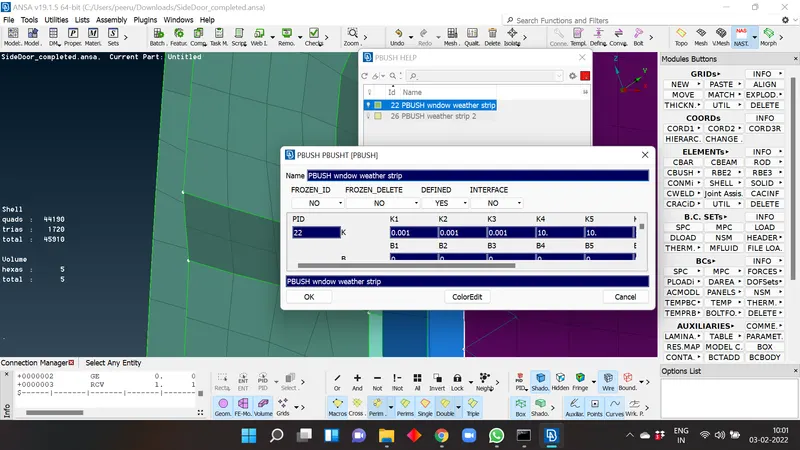
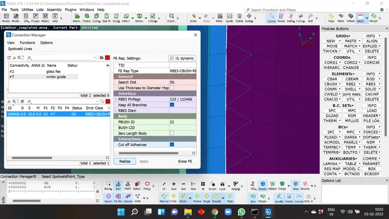
Now again go to connection manager select any one of the spotline >select the FE representation as RBE3- CBUSH-RBE3> give the search distance and create the PBUSH id for cbush and give the stiffness values (K) as shown above > select the glass and adjecent part as P1, P2 . Also don't forget to give the the space value (S) betweeen each bush, for this challenge I have given the 10 as space. now, upon apply and realising the bush will get generated.
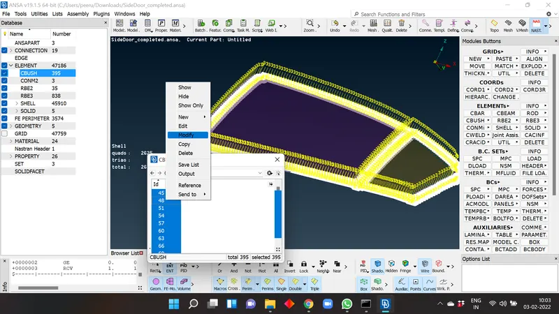
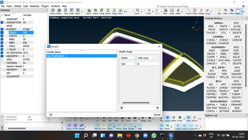
Generated bush is aligned with local co-ordinate , this individual alignment of co-ordinate can generate the deviations while at simulation stage, to avoid these deviations we need to orient the cbush alignment in selected orientation or align them to global coordinates. for that open database> elements>cbush>> select all cbushes >upon right click >select modify > select/ type orient > select the cord. again press plus option select/type CID > enter 0 > press ok. now all cbushes will aligned to global co-ordinates.
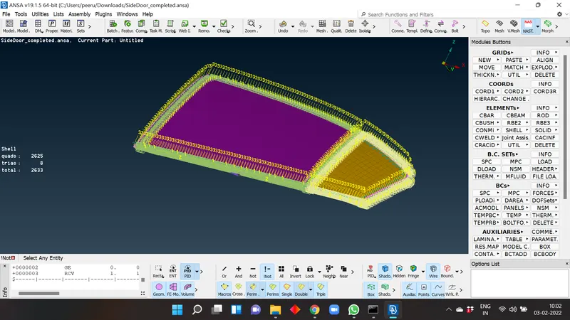
with this we cover all the different kinds of connections in the ANSA nastran deck.
Learning outcomes:
- Learned about various kinds of connections which were used in the Nastran deck
- Learned how to convert the curves and points to various kinds of connection representations.
- Learned about Tailored structure used in real life applications to reduce the cost and weight of the body.
- Learned about weather strip usages around the side glass and wind sheilds in automobiles.
CONCLUSION: After assignment of individual PID's for every element the system was deployed with various kind of connections at every mating surfaces and every element was rigidised in the FE model of the rear side door.