Week 3 - 2D meshing for sheet metal
CAR HOOD MODELING USING ANSA PRE-PROCESSOR
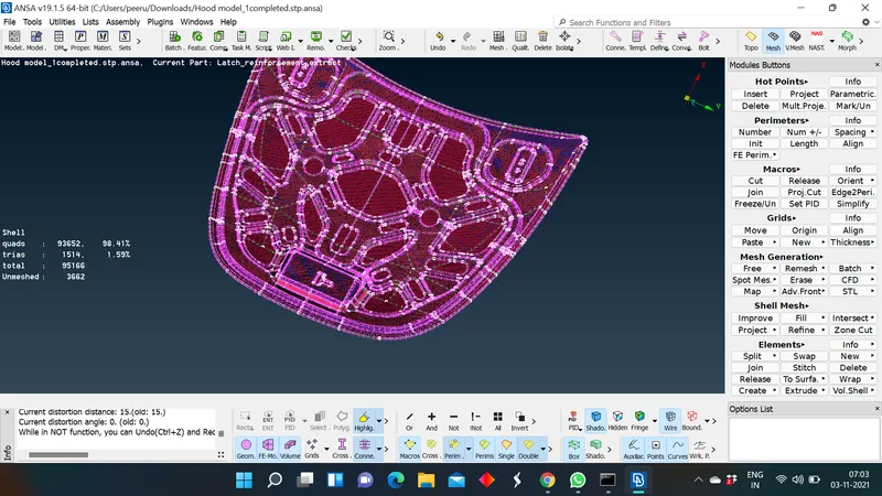
Aim: For given car hood model a mid surface should be generated and shell mesh should be performed on the repective mid surface and thickness should be assigned to mid surface.
Methodology:
- Import the CAD model into ANSA software.
- Geometry cleanup and geometry errors should be addressed initially.
- Mid surface generation of every component.
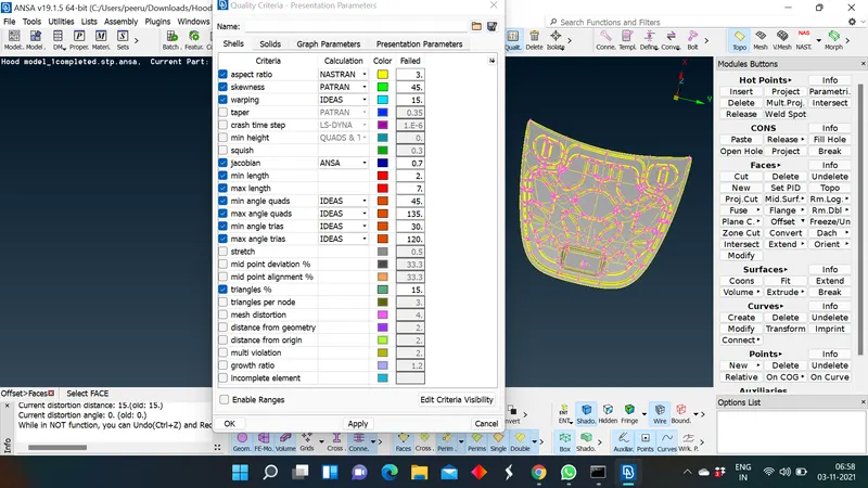
- Setting the quality and mesh criteria.
- Defining the respective thickness to the mid surface.
- Individual mesh generation on every component.
- Addressing mesh off elements and improving the mesh flow.
- Thickness assignment for the mid surface.
Quality criteria:
|
S.No |
Quality Criteria |
Value |
|
1 |
Target/Average length |
5 |
|
2 |
Minimum Length |
2 |
|
3 |
Maximum Length |
7 |
|
4 |
Aspect |
3 |
|
5 |
Warpage |
15 |
|
6 |
Skewness |
45 |
|
7 |
Jacobian |
0.7 |
|
8 |
Minimum Quad Angle |
45 |
|
9 |
Maximum Quad Angle |
135 |
|
10 |
Minimum Tria Angle |
30 |
|
11 |
Maximum Tria Angle |
120 |
|
10 |
Tria Percentage |
15 |
Theory:
The hood or bonnet is the hinged cover over the engine of motor vehicles. Hoods can open to allow access to the engine compartment, or trunk on rear-engine and some mid-engine vehicles) for maintenance and repair.
On front-engined cars, the hood may be hinged at either the front or the rear edge, or in earlier models it may be split into two sections, one each side, each hinged along the centre line. A further variant combines the bonnet and wheelarches into one section and allows the entire front bodywork to tilt forwards around a pivot near the front of the vehicle.
Hoods are typically made out of the same material as the rest of the body work. This may include steel, aluminum, fiberglass or carbon fiber. However, some aftermarket companies produce replacements for steel hoods in fiberglass or carbon fiber to make the vehicle lighter.
The hood release system is common on most vehicles and usually consists of an interior hood latch handle, hood release cable and hood latch assembly. The hood latch handle is usually located below the steering wheel, beside the driver's seat or set into the door frame. On race cars or cars with aftermarket hoods (that do not use the factory latch system) the hood may be held down by hood pins. Some aftermarket hoods that have a latch system are still equipped with hood pins to hold the hood buttoned down if the latch fails.
Procedure:
- Import the CAD model into ANSA : After starting the ansa in Performance_mode 3 import the model which need to be modeled in ANSA preprocessor.
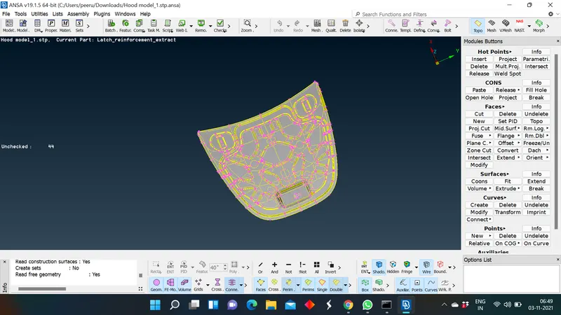
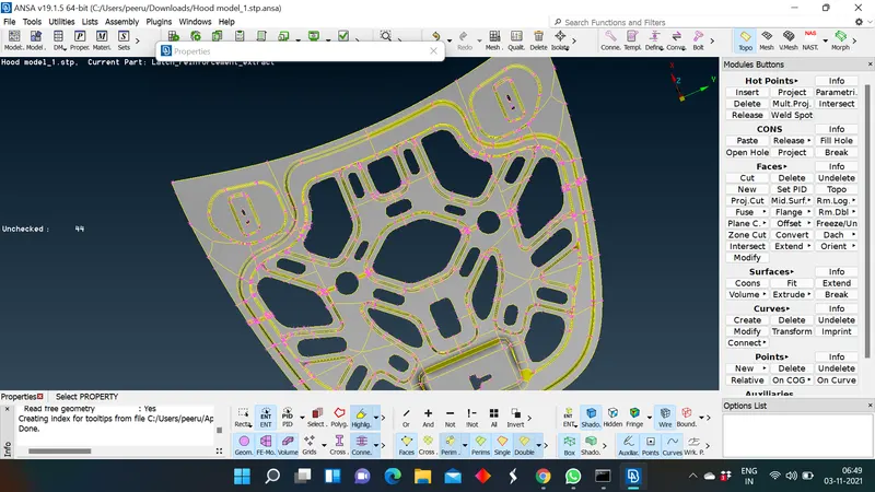
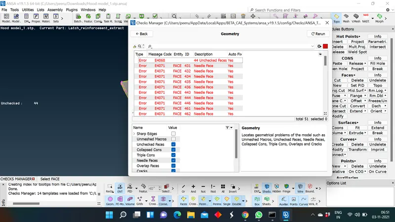
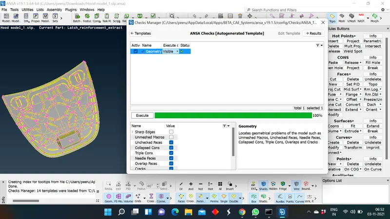
- Geometry cleanup & fixing the errors: Before generating the mid surface for individual components we need to clean the geometry and make it error free. initially, use TOPO to stitch the cons together. after performing TOPO on individual components you can go to CHECKS manager to check for the errors and by selecting all and giving auto fix command we can fix errors, ANSA fix those errors automatically. Even after giving auto fix if there are any errors manual intervention is required and error should be fixed maanually.
- Mid surface generation : Due to the complexity of the model we need to generate mid surface individually for every component. we turn off the other properties in PID section and keep a single component at a time. It is is sheet metal model so there will be uniform thickness through out the component but for confirmation we measure the component thickness. For mid surface generation we use offset option in faces section. By using offset option we generate the mid surface for every component in the model. (offset>features>40 degree> select one side of component > by left click you can now mention the half of the thickness value as offset value to generate the mid surface > ok). Based on the orientation and shown direction of arrow you need to decide the negative sign infront of the offset value.
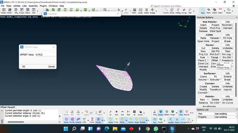
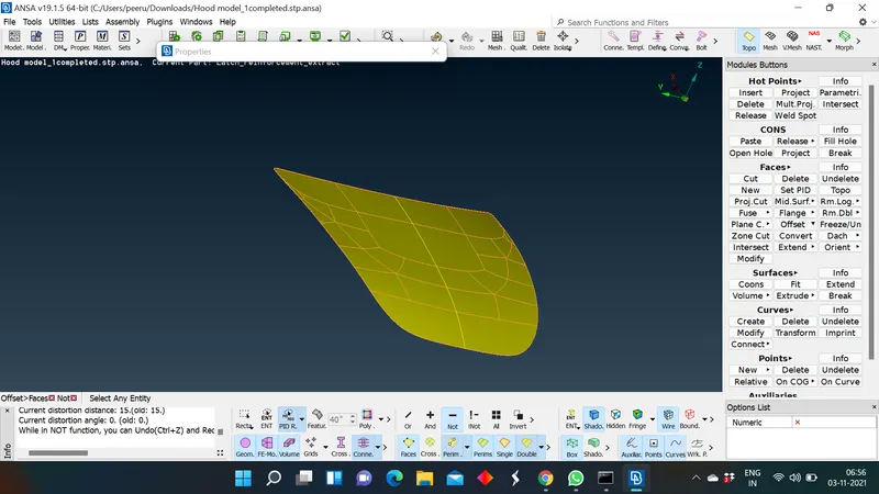
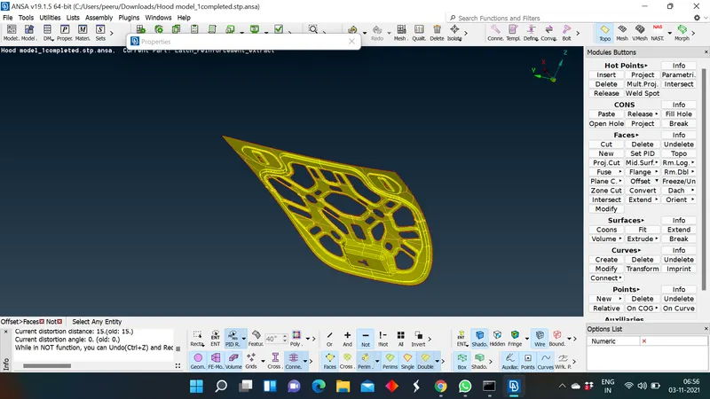
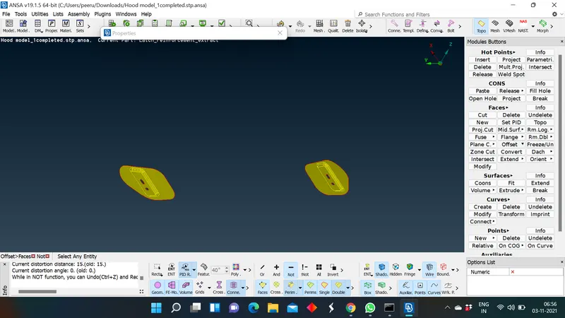
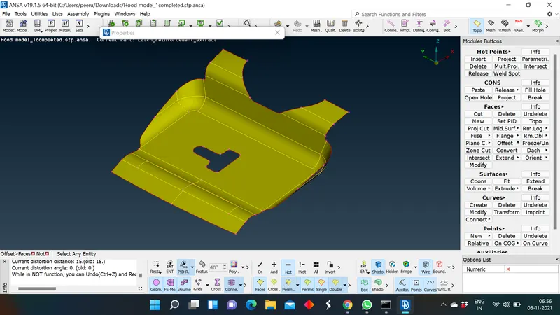
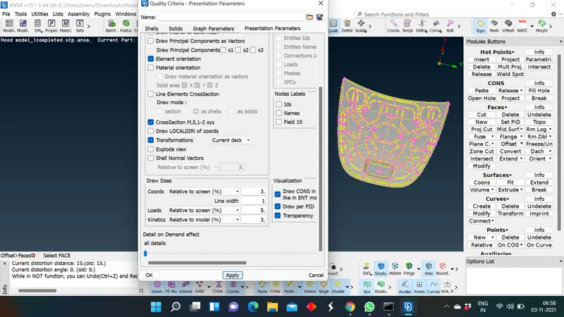
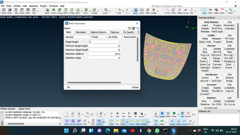
- Setting the quality and mesh criteria's for meshing: After mid surface generation we set the quality criteria for meshing the mid surfaces as required in Quality section.
- Defining the thickness for mid surfaces: Before proceding for meshing the mid surface we give the thickness for mid surfaces which we generated. we asign the thickness of the parent component as the thickness of mid surface in PID section.
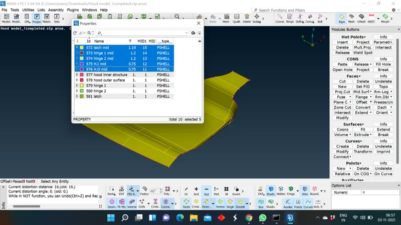
- Individual mesh generation on every component: Before proceding for mesh generation we need to remove the cons which fail for min length criteria. This is called deforming the features. In order to solve this Min length error, One can toggle (suppress) the top and bottom double cons at the fillet region of a mid surface (Toggled cons will be represented as Orange colour lines). This is called ‘defeaturing’ the midsurface. (Refer the below image to understand the same). Doing this will change the FE shape upto smaller extent, which is allowable to solve Failed elements. After addressing these problems we will eliminate the unnecessary cons by using cut option, these cons does'nt effect the features of the component and by keeping these cons the mesh flow wil get effected. To get a better mesh flow we remove these cons.
After deforming we goto mesh section> select length> select total component and give the target length as criteria for re-arrange the element length so that the mesh nodes will does'nt fail teh quality criteria. Now, we can generate the mesh using option like batch mesh, spot mesh to generate the mesh on the component.
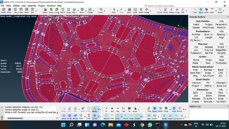
- For addressing the off mesh elements we will use several option like split , paste ,move, these options were used to eleminate the trias in the mesh. For get better mesh flow we use the reconstruct option and we rerun this option untill we get better mesh flow in the selected area. By using these options we can eliminate mesh off elements and get the better mesh flow.
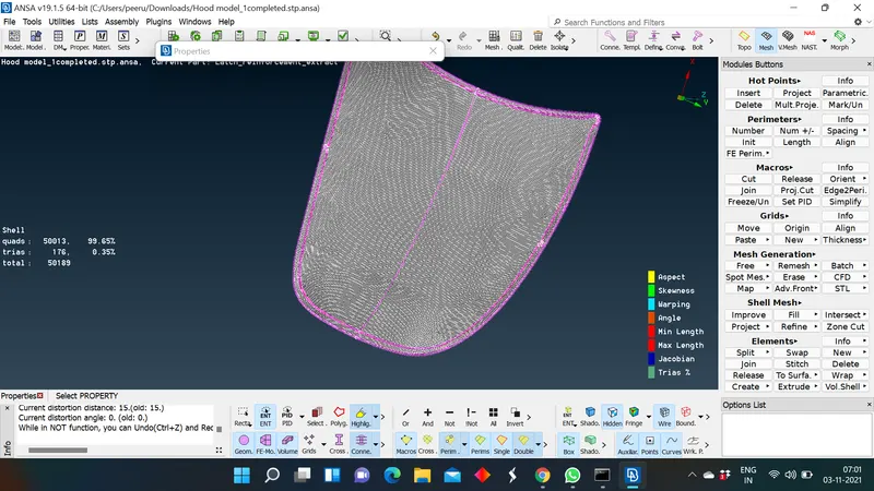
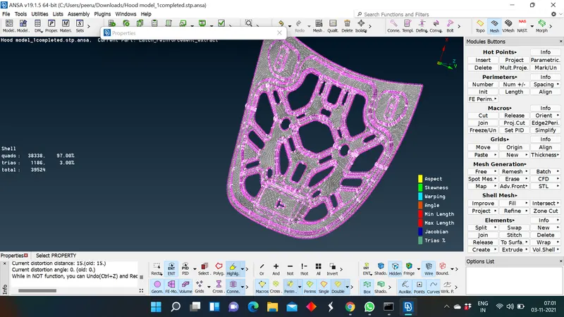
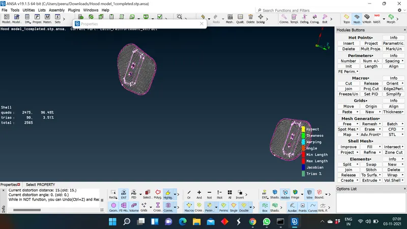
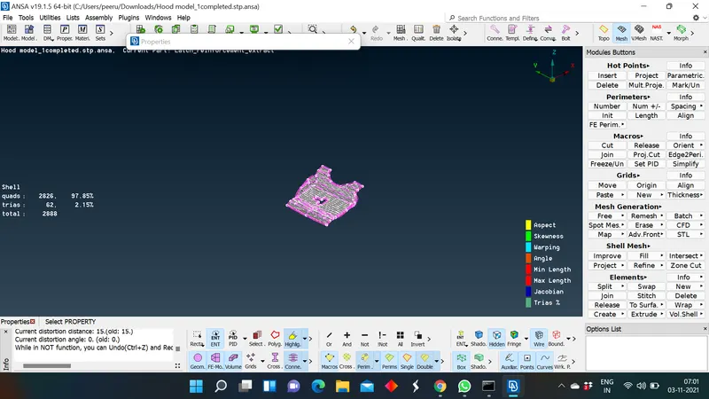
- Assigning the thickness for the mid surface: After mesh generation we can assign the respective thickness for the mid surface by selecting the option called shell to solid in quality criteria by which ANSA assign the repective thickness to mid surface that we mentioned in the Propertes ID.
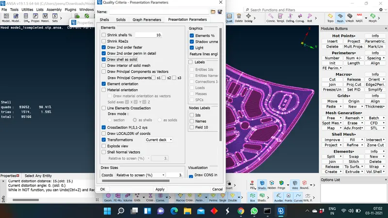
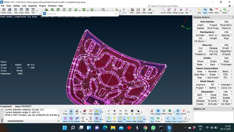
Here , we can check whether the assigned thickness is correct or not by saw the mesh on the parent component, If the mesh is comming out from the parent component then the assigned thickness is more than what parent component has on it. If mesh was not seen on the surface which says that the assigned thickness is less than the parent components thickness. one can solve this issues by changing the thickness in properties ID, even though if you were not been solving the issue then there is an problem with the mid surface placement.
Conclusion: The car hood model is modeled using the ANSA preprocessor , we generated the mid surface for all coponents and mesh is generaed on every component and the thickness is assigned for the meshed mid surface.
Learning outcomes:
- I learned how to generate a mid surface and how to mesh the mid surface using ANSA.
- In this challenge I got to know how to deform the features at fillet areas to catch the max area for meshing.
- I got to know how to assign the thickness for meshed mid surface.