Week 6 - Creating connection for Rear door
Aim
For the given Rear Door:
a. Genererate the different PID's for different components
b. Deploy the suitable connections for all the mating shells and elements.
Procedure
First of all the given Rear Door subsystem was opened in ANSA and this subsystem was meshed already with a predefined quality criteria and then first of all the hinge joint assembly was connected with the suitable connections as per the given figures below:
1. Bolt Connections
First of all the bolt connection were deployed in the two mating holes as given below
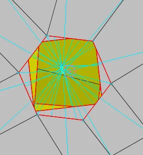
3D point was generated on the belowmost hole using the on COG command in TOPO mode. Using connections option in the tool bar, the 3D point was converted to the bolted point. Going through the connection manager, the asked P1, P2 and P3 surfaces were selected by going through the different PID's assigned to diferent shells and in the connection properties section, the bolt was selected. RBE2 connection was used for connection sense. This was a body oriented bolt connection and so that the body of bolt connection was visible from the bottom most surface to the upper surface. After this, pressing the apply option and then realise the bolt connection, bolt connection was generated for the given three holes. Since three holes were available so we have used the body oriented bolted joint.
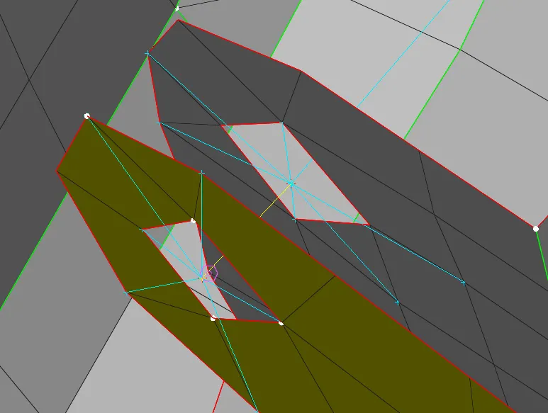
2. Cluster RBE2 Connection
Cluster RBE2 connection has the master node at center and the slave nodes at the corners. This connection has been used to connect the two holes directly which were directly one above to each other. To generate RBE2 connection fist the NASTRAN deck was selected and then in the elements section, RBE2 connection was selected. After this, with the selection multi node selection it has asked to select the number of nodes which had to be connected. For selection of nodes, loop selection was used and afterwards connection was completed. RBE2 cluster connection was looked like as below:
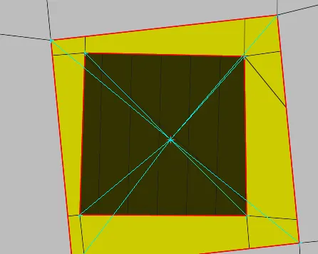
Below is the RBE2 connection for hinge joint between the two portions of this joint:
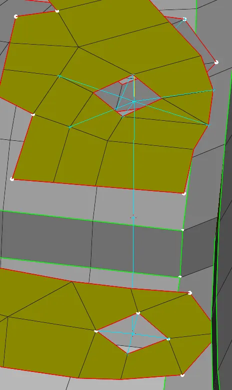
Here only 5 degrees of freedom were arrested and the only degree of freedom for this joint that is open is the rotation about the Z-axis. This is because the door has to be opened by rotating around Z-axis.
3. Spot Weld Conections
Spot weld connections are generally deployed to the mating surfaces where holes are not available and in this system, it was used to establish a connection between rail mechanism and the body of door. Representation of this connection is as below:
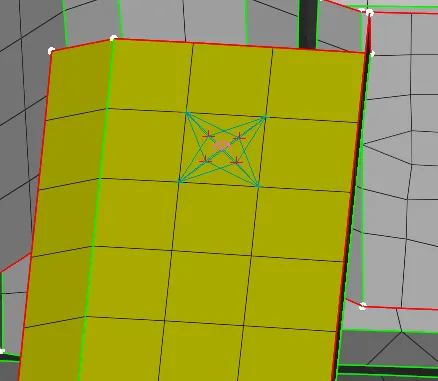
After creating a 3D point on selected mesh element as shown in figure the point was then converted to the spot weld joint. After this using connection manager, the mating surface FE elements were selected for both the mating surfaces and for the connection representation RBE3 Hexa spot connection was selected. RBE3 connection has the master nodes on the corners and the slave node is on the middle.
4. CBUSH Connections
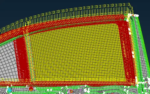
This connections are used for the glass with the parent body with the use of rubber pads. These connection are used to provide the stiffness in the diferent directions. First of all on the periphery of then Glass surface, curve has been generated using FEAT TO Curve option in Mesh Module. After generating the curv on the periphery, lower surface peripheral curve was copied at the distance of 1 form the parent one. This is because from the lower side, the glass surface has to be connected from two sides. To impart a CBUSH connection between the two mating parts, first the periphery curve has to be transformed to the spot line and then going to the connection manager we have selected the two mating surfaces. With assigning the P1 and P2, the CBUSH element was selected in the dialog box. Searching distance was assigned as 60 and then the new PSOLID ID was made and in that stiffness values were assisgned as 5 for each and every direction. After assigning the PSOLID ID, the realization of CBUSH connection was successful as shown below:
Learning Outcomes
a. Learned to deal with Door Connections
b. Got the conception of different types of connections used in Door Assembly
c. Way to deploy the different connections
d. Learned, which type of connections are used for two mating surfaces.
Conclusions
a. PID's were assigned to different surfaces of the given Rear Door subsystem.
b. Different types of connections were deployed successfully for the given subsytem.