Week 1 Stress Concentration on a Plate with hole
Aim: To compare Structural analysis results of two given plates with holes using ANSYS Workbench.
Objectives:
a) Design a plate with hole using ANSYS Spaceclaim
b) Design a plate with 3 holes using ANSYS Spaceclaim
c) Determinaton of Max stress and Total deformation in thw two given plates
d) Comarison of the results for two plates
Introduction to Stress Concentration:
Stress concentration is defined as the localization of stress due to irregularities and sudden change in cross sectional area of the given specimen. It can be defined as the ratio of maximum stress at the irregularity and nominal stress (governed by standard strength criteria).
In general, Ductile materials deal more safely with stress concentration because these materials have a special phenomena called yielding. On the other hand, brittle materials have not such kind of phenomena or any other mechanism that compensate the stress concentartion.
Given:
Height - 120mm
Length - 300mm
Thickness - 30mm
Hole Diameter - 60mm
hole is at the middle of the plate
b) for the second plate
plate:
length - 300mm
height - 120mm
thickness - 30mm
Holes:
smaller holes:
diameter - 30mm
90 mm away from the centre
larger hole:
diameter - 60mm
at the centre of plate'
Procedure:
a) First then static structural option was selected out of the given options in then analysis types in ANSYS Workbench.
b) Engineering data was selected (Structural Steel as material etc.)
c) To impart the geometry, first spaceclaim was opened and then the geometery was constructed as below:
for both the cases first a basic rectengular was made using rectengular command and after that the dimensions were given for the sides
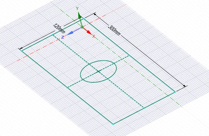
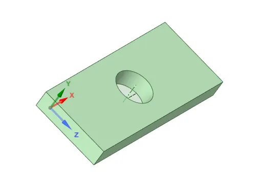
Extrusion option was selected to make the given sketch as a solid component by giving the extrusion distance 30 mm as below:
case 1
case 2
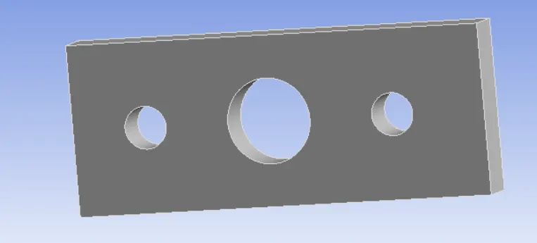
ANSYS has automatically extracted the geometry when we select the model option in workbench.
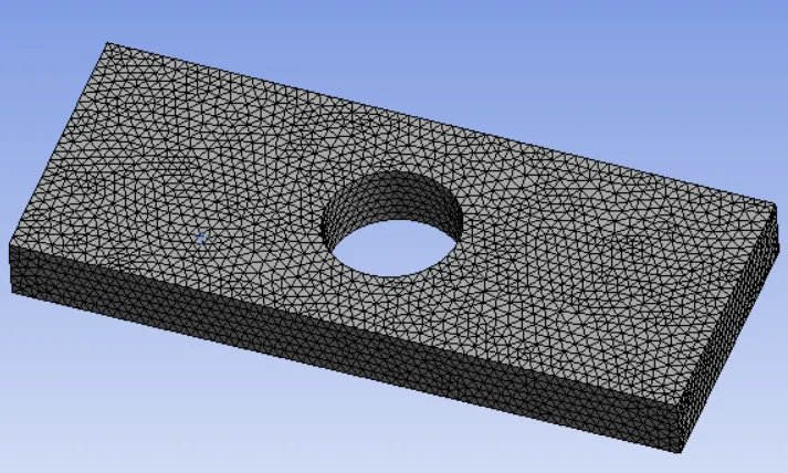
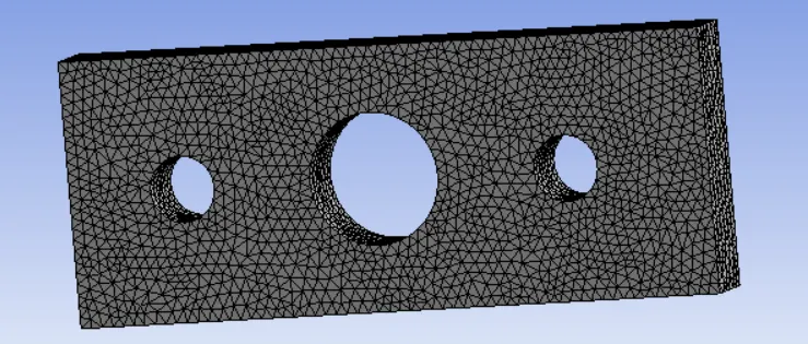
d) By selecting model now we are in ANSYS Mechanical module and then mesh generation was done by element size of 5 and tetrahedran mesh elements shape was selected as given below:
case 1
case 2
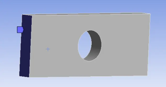
e) To give the boundary constraints, first the fixed support was made at the left face of plate as given below:
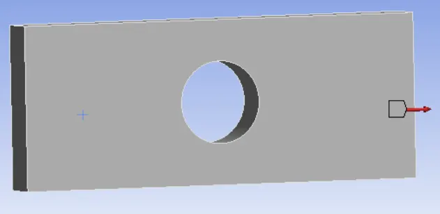
f) After this the load of 500N was given at then right face of the plate as below:
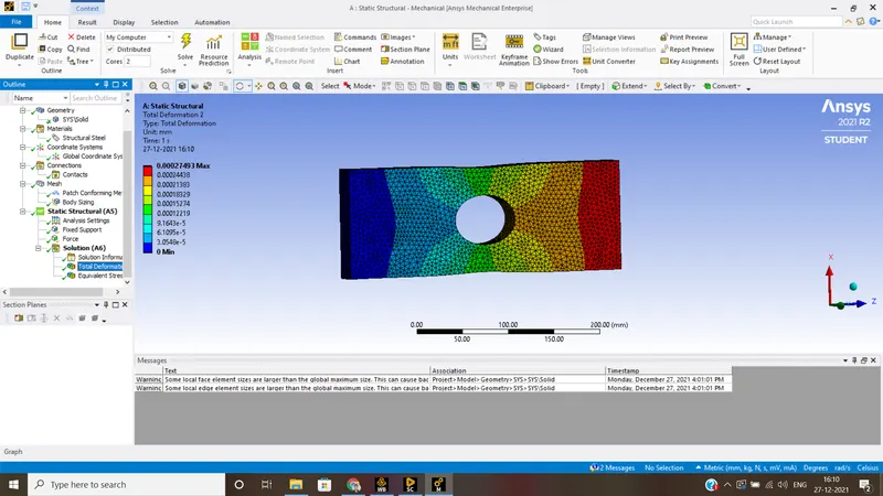
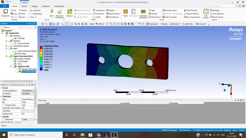
g) for solution, first the solve option was selected and then total deformation and the stress were added to the solution as below:
Total Deformation:
case 1
case 2
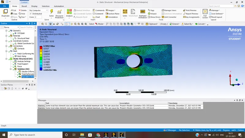
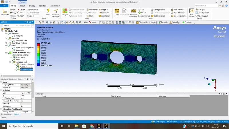
Similarly, the total stress was also analysed as given below:
case 1
case 2
Results:
For the plate of single hole:
Total Deformation (Maximum) - 0.00027493 mm
Total Deformation (Minimum) - 0
Total Stress (maximum) - 0.59923 MPa
Total Stress (Minimum) - 0.0094567 MPa
For the plate containing three holes:
Total Deformation (Maximum) - 0.00029522 mm
Total Deformation (Minimum) - 0
Total Stress (Maximum) - 0.57529 MPa
Total Stress (Minimum) - 0.002226 MPa
Conclusions:
a) For the given plates, we have seen that the total deformation is lesser for plate containing single hole.
b) On then other hand, stress value in case of single hole plate is higher than that of plate with three holes.
c) For analysis point of view, we have to select plate 2 because the max value of stress is lesser and design is safer.
d) For manufacturing point of view, we have to select plate 1 because of availability of single hole only and this will minimise the total cost and will increase the manufacturing ease.