Week 6 - Creating connection for Rear door
CONNECTIONS: REAR DOOR.
AIM: To deploy connections in different parts of door.
PROCEDURE: 1) Open the rear door model in ANSA.
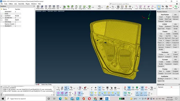
2) Check for the geometry.
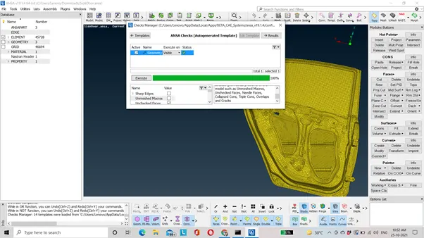
3) Assign the PID at different part of the rear door model.
MESH/PID→SET PID→SLECT THE ENTITY→MIDDLE MOUSE CONFIRMATION→NEW→GIVE NAME (PID 1) →IF YOU WANT YOU CAN EDIT COLOUR→OK.
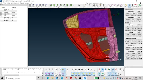
4) Two different PID is assigned on the outer panel in order to reduce the weight and the cost of the door. Taylor weld approach is used. The region near the hinge will be thicker than the other portion.
5) Now we will do connection at different part of the rear door. At the hinge part we will use clustered RBE2 and two node RBE2. While deploying clustered RBE2 we should unconstrained one degree of freedom that is rotation along Z-axes for opening and closing the door.
FOR DEPLOYING CLUSTERED RBE2:
NASTRAN DECK→ELEMENTS→RBE2→SELECT SLAVE NODES (THE NODES AT THE PERIMETER OF BOTH THE HOLE) →CONFIRM→MASTER NODE WILL BE AUTOMATICALLY GENERATED→CONFIRM→WE CAN SAVE THE PART BY CREATING NEW FOLDER→FINISH.
FOR DEPLOYING TWO NODE RBE2:
NASTRAN DECK→ELEMENTS→RBE2→TWO NODES →SELECT THE MASTER NODES OF CLUSTERED RBE2 ELEMENT→CONFIRM →OK.
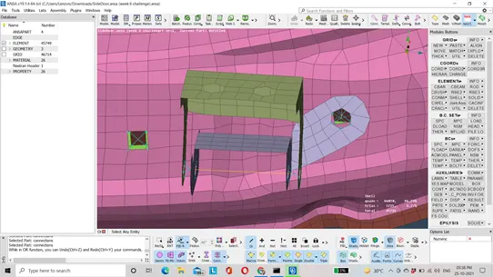
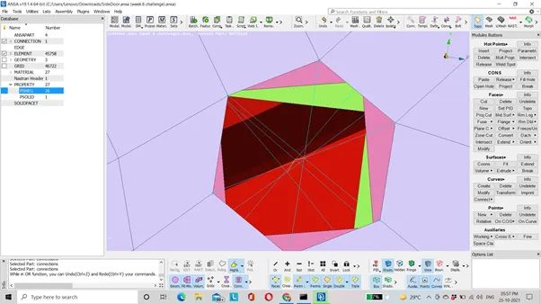
6) Here, in the region which is shown in above image. We will use combination of many node RBE2 and two node RBE2. Two node RBE2 is used to represent the stem or shaft.
TO DEPLOY MANY NODE RBE2:
NASTRAN DECK→ELEMENTS→RBE2→MANY NODES →SELECT THE SLAVE NODE →CONFIRM.
NOTE: Create a many node RBE2 separately for all the holes.
TO DEPLOY TWO NODE RBE2:
NASTRAN DECK→ELEMENTS→RBE2→TWO NODE→SELECT THE MASTER NODES→CONFIRM →OK.
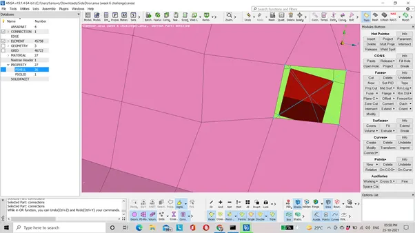
7) The region which is shown in above image there we will use clustered RBE2.
8) The region where the gap between two part is very less it is recommended to use spot weld.
Steps to generate spot weld:
1)Create COG.
2) Convert COG into 3D point.
ASSEMBLY→CONVERT→3D POINT→SPOT LINE→CONFIRM.
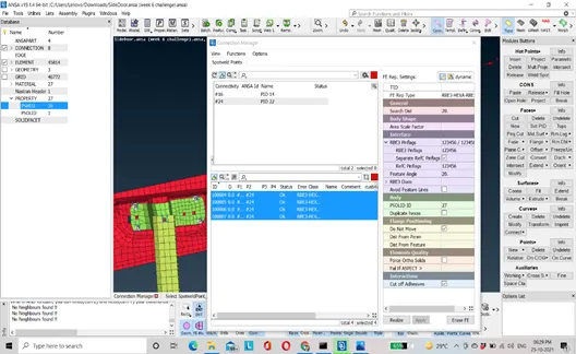
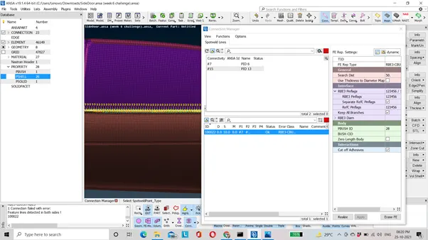
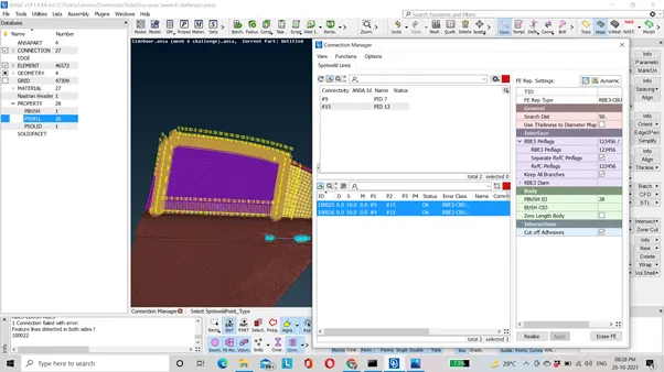
3) ASSEMBLY→CONNECTION MANAGER→SELECT PARTS WHICH IS TO BE SPOT WELDED (P1, P2…) →FE REPRESENTATION(RBE3-HEXA-RBE3) →ENTER THE SEARCH DISTANCE (USER DEFINE) →RBE3 PINFLAGS (123456) →ASSIGN SPOT WELD PID) (SHIFT+?) → APPLY →REALIZE.
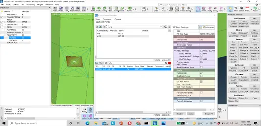
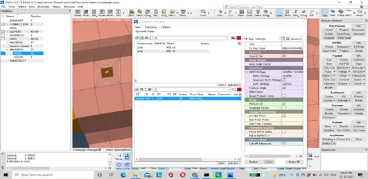
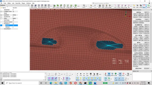
9) Now we will do connections at door handle. It is a mass element.
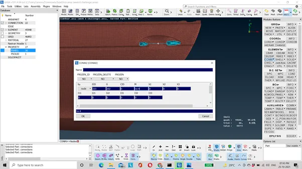
To deploy connection at door handle, use many node RBE2. Now to give mass.
NASTRAN DECK→ELEMENTS→CONMi→CON2→NODES→ENTER MASS VALUE IN TONNES→OK.
10) Now we need to deploy the connection at the window for that we have to first create a curve.
NOTE: Glass will be modeled in close position.
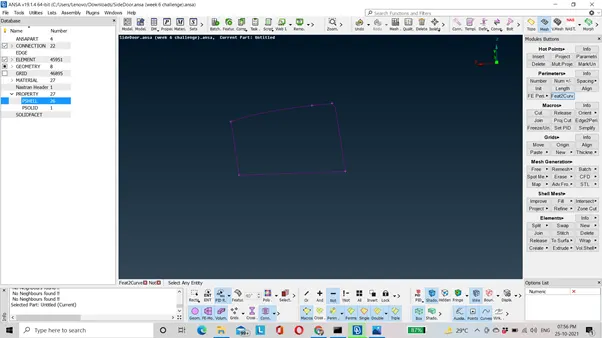
MESH→FEA2CURVE→SELECT THE LINE FOR WHICH CURVE NEEDS TO BE CREATED→OK.
Now convert all the curve one by one into spot line.
ASSEMBLY→CONVERT→SPOT LINE→CONFIRM.
ASSEMBLY → CONNECTION MANAGER→SELECT THE PARTS BETWEEN WHICH C-BUSH CONNECTION NEEDS TO BE DEPLOYED (P1, P2, …) (RIGHT CLICK →PRESS F1) → ENTER S=10→FE REPRESENTATION (RBE3-C-BUSH-RBE3) →ENTER SEARCH VALUE→ENTER RBE3 PINFLAGS (123456) →ASSIGN PID (ENTER STIFFNESS VALUE AS 0.001,0.001,0.001,10,10,10) →APPLY→REALIZE.
Now apply same procedure to deploy c-bush connection for other curves.
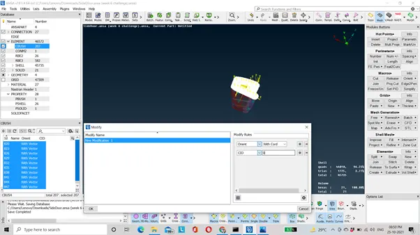
If we will observe all the c-bush element will have different vector direction in order to make local co-ordinate direction of c-bush similar to global co-ordinate.
ENABLE ORIENT AND CID OPTION →SELECT ALL THE C-BUSH ELEMENT→RIGHT CLICK →MODIFY→ ORIENT→WITH VECTOR→CID→ZERO→OK.
Difference between RBE2 and RBE3:
In RBE2 elements the slave nodes are the perimeters nodes and master node is COG whereas in RBE3 it is completely opposite.
RBE2 elements do not have property ID so we cannot use it where we have to assign property ID for connections but this case is not there with RBE3 elements.
LEARNING OUTCOMES: 1) To deploy connections using many node RBE2, Two node RBE2 and clustered RBE2.
2) Difference between RBE2 AND RBE3 elements.
3) To deploy spot weld connection using RBE3-HEXA-RBE3 element.
4) To create connection using RBE3-CBUSH-RBE3 element.
5) Which type of connection needs to be done at different region means only clustered RBE2, Combination of clustered RBE2 and two node RBE2, spot weld etc.
CONCLUSION: Hence, connection is deployed at different part of the rear door model.
TO DOWNLOAD THE MODEL PLEASE CLICK ON THE LINK GIVEN BELOW:
https://drive.google.com/file/d/1aBBSkcF4uZDJ8-ywenh87QAbNjSSumLD/view?usp=sharing