Week 6 - Creating connection for Rear door
- AIM:
To create appropriate connections and deploy the relevant PID's of the given rear door component.
- PROCEDURE
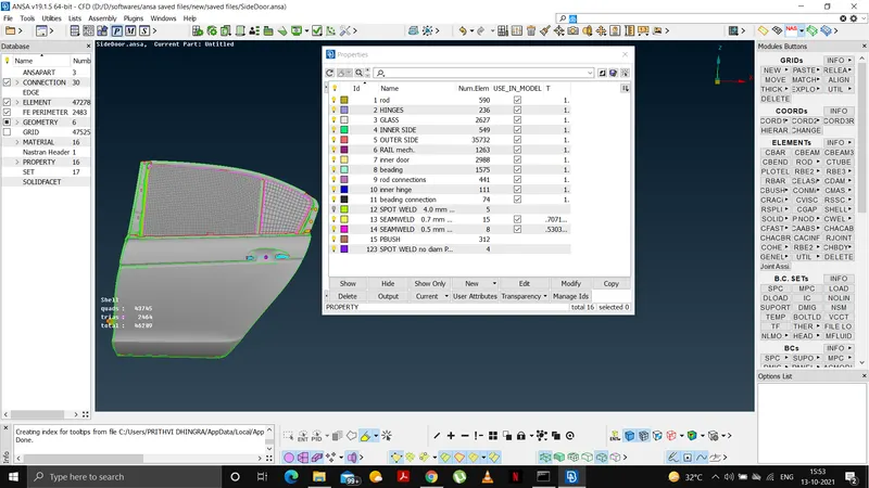
Set initial PID's for the different parts as shown-
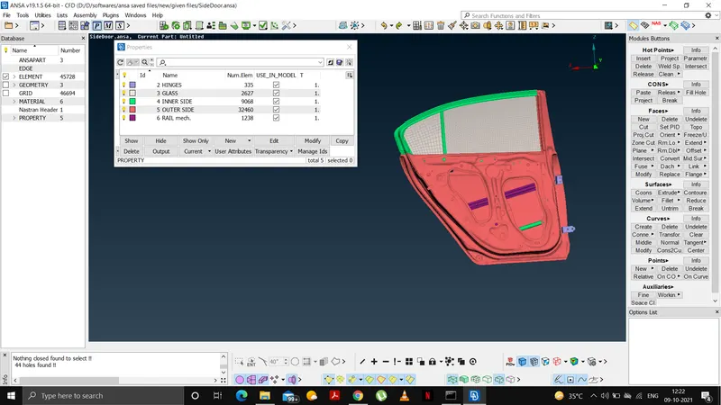
Deploy the connections for HINGES as shown below-
--Create COG points-select from points-on cog-edges
--Select the edges and click middle mouse button for a COG
--Selecting these COG points and using convert , convert them in 3D points from assembly option as shown-
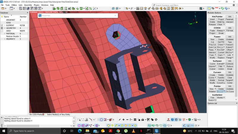
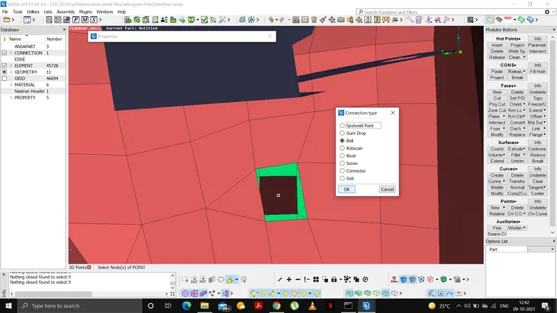
--Then select these and create bolt from connections manager and give appropriate info as shown below.
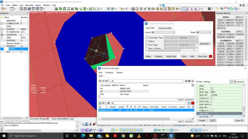
--Type- RBE2-bolt
--DOF-123456
--select appropirate P1, P2 and P3.
--Then connections are deployed as rbe2 to make several rigid components by RBE2-element-->many nodes from NASTRAN deck module.
--CM(DOF)-12345/6- to constraint in z direction.
--Select master nodes wherever required and/or 2 nodes option where Z-direction is not constrained.
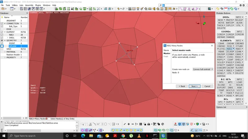
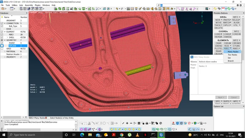
Deploy the connections for DOOR HANDLE as shown below-
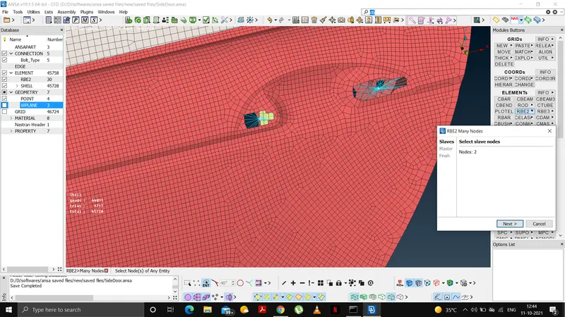
--First of all, RBE2-many nodes is selected to creat a rigid body for the handles.
--Then a master node is used to join the two components.
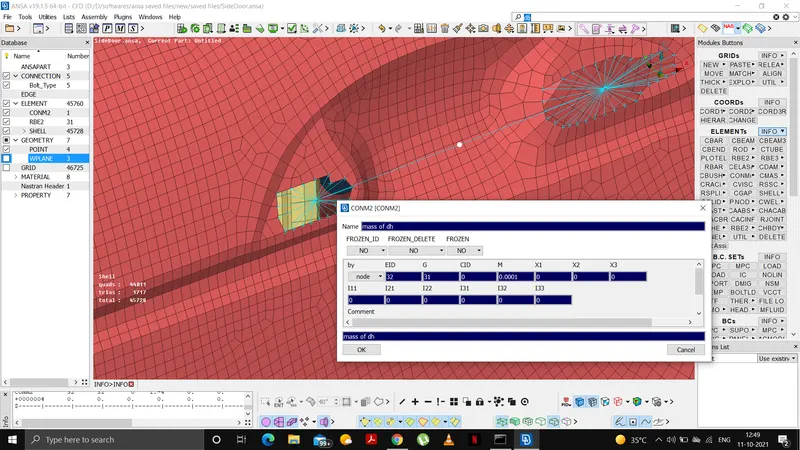
--We did this because if we use only 2 nodes option then we cannot specify the master node which we require to give mass of the door handle as shown.
--To show the mass of the door handles we select CONMi-->CONM2 from nodes in the NASTRAN deck as shown below and set the mass as 1e-4 which is 100 gm which is 0.0001 tonnes.
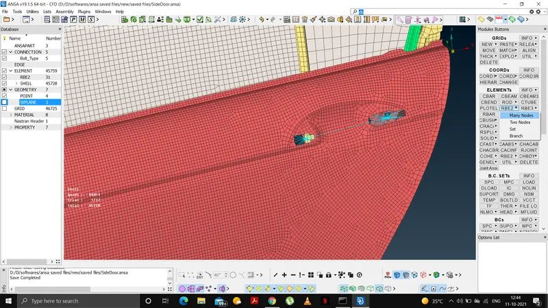
Deploy the connections for LATCH as shown below-
--Latch is used for the locking mechanism of the door. It is also connected using RBE2 element-many nodes from the NASTRAN deck.
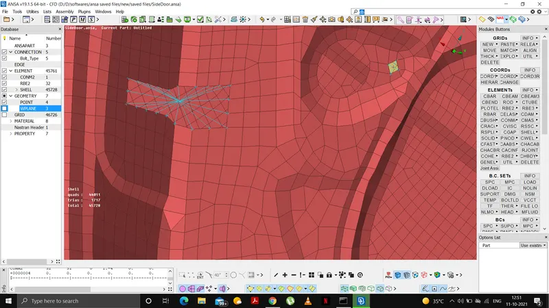
Deploy the connections for rail and glass as shown below-
--First of all, isolate the rail and glass as shown below.
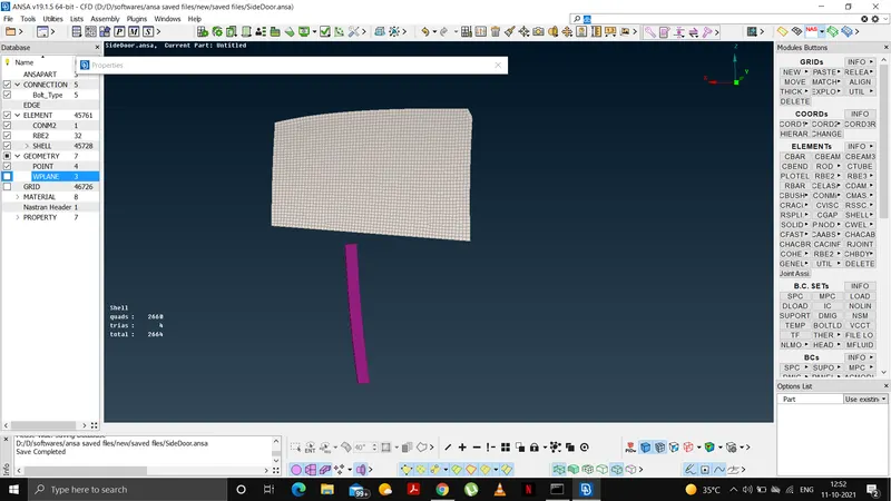
--Using MV free option from utility bar move the rail to overlap the window so that we can make a connection.
--Then split the mesh using split command under elements options in meshing bar-->modules buttons.
--Then reconstruct the rail as shown below for a better mesh from shell mesh.
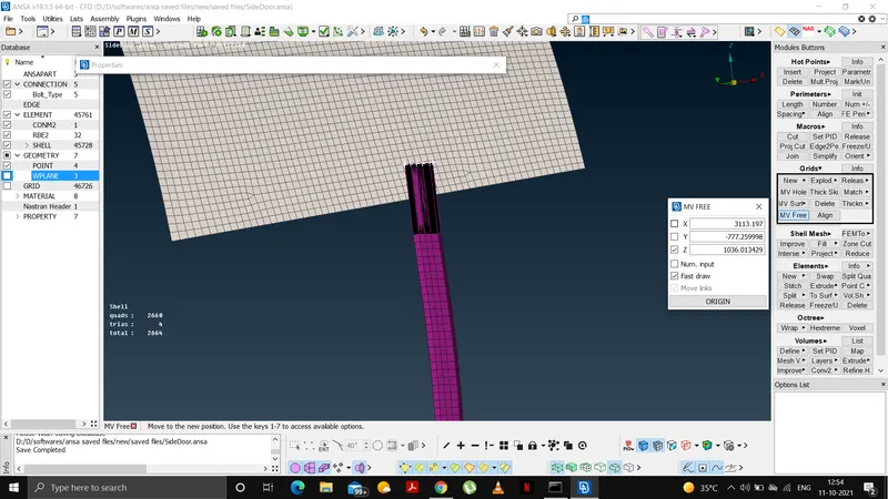
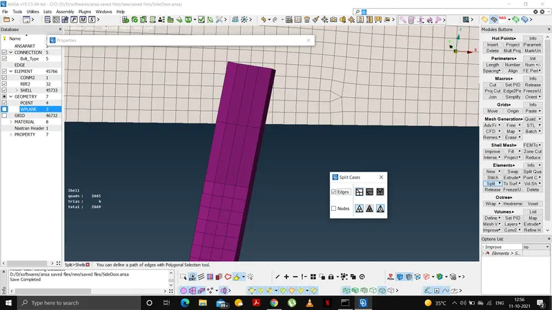
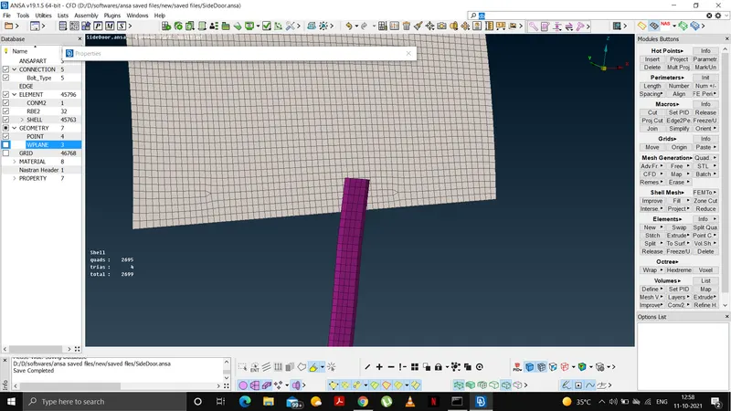
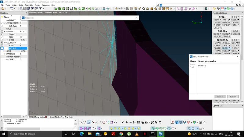
--Then using RBE2 cluster-->many nodes connect the rail and the glass for a rigid connection as shown below.
Deploy the connections using spot weld as shown below-
-- First create a COG point using on COG-edges and select the region to deploy the point.
-- Then using convert, convert the points to 3D points using convert tool.
--Then convert the 3D point into spot weld from connections manager and give details as follows-
type-RBE3-HEXa-RBE3
search dist-50
DOF-123456
select the appropriate PID's(P1,P2)
--Finally click apply and then realise.
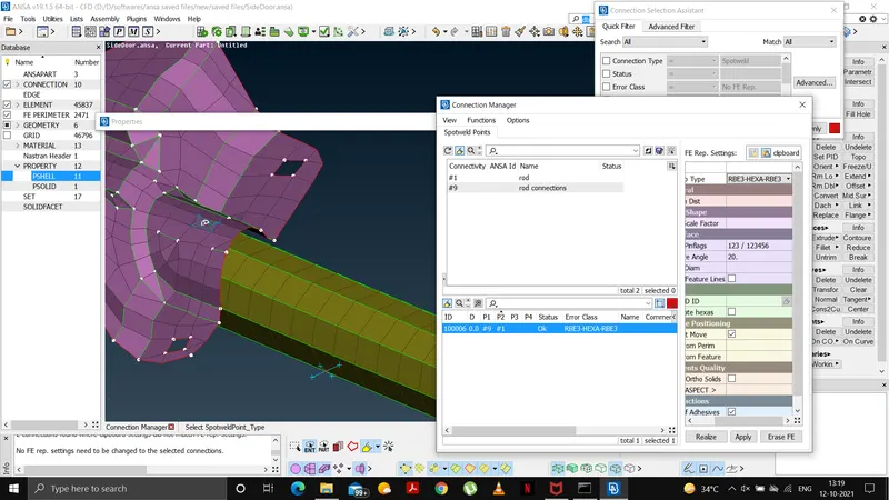
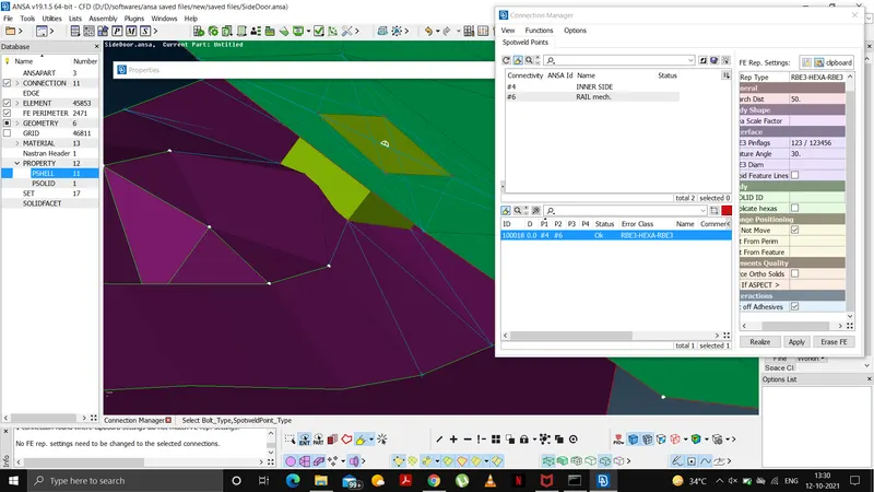
Follow the above procedure wherever a spot weld is required.
Deploy the connections for hinges and beading as shown below-
--Using FEA2CURVE option from perimeters option, convert the single con into a curve.
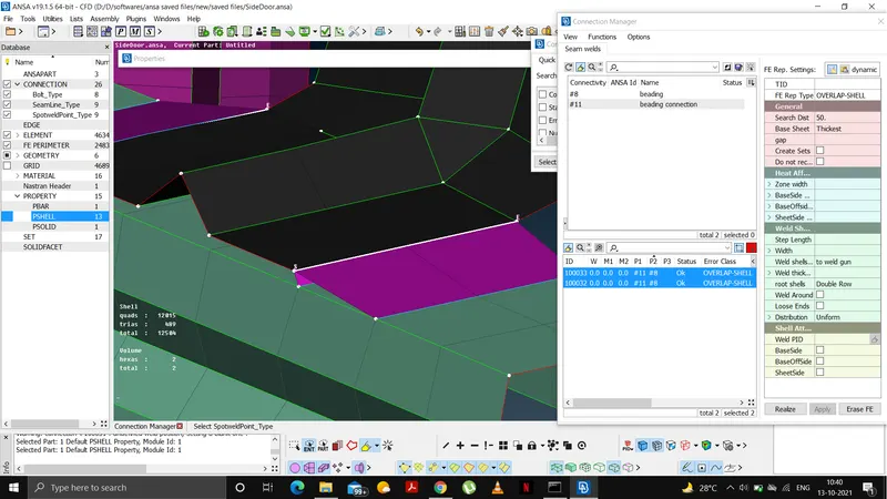
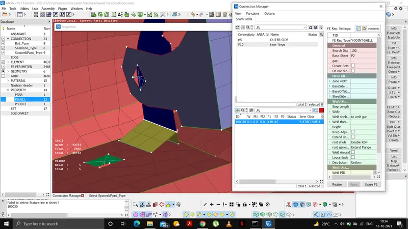
--Then convert the curve into a spot line using the connections manager.
--give search dist as 50 and select appropriate pid's(P1,P2)
--For hinges, select the type as Y-JOINT SHELL
--For beading, select the type as OVERLAPPED SHELL.
--Follow the procedure as shown below-
Deploy the connections for glass as shown below-
--For the beading/weather strip, we first convert the single con into curve using FEA TO CURVE option from perimeters bar.
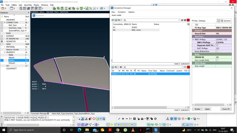
--Then we convert this curve into spot line from connections manager as shown below-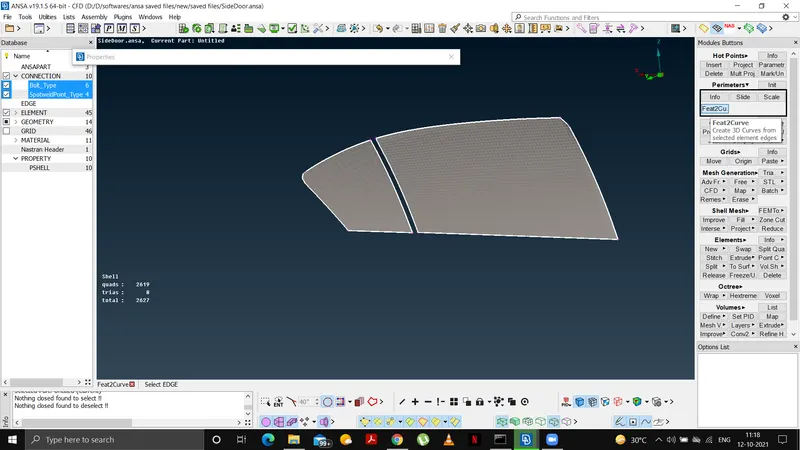
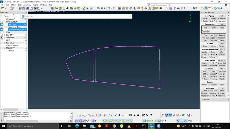
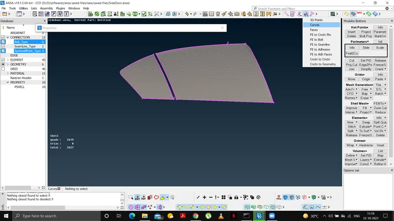
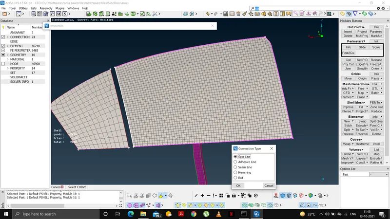
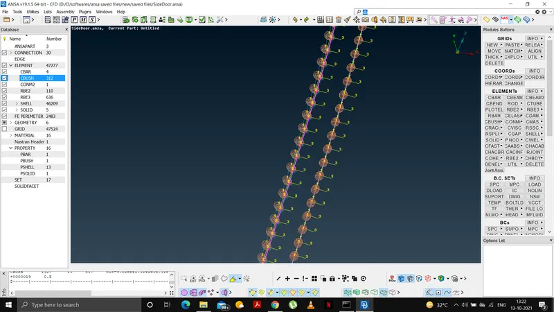
--To realise a CBUSH we first need to move this curve.
--Using transform options from utitliy bar we copy the curve 10mm in dy direction.
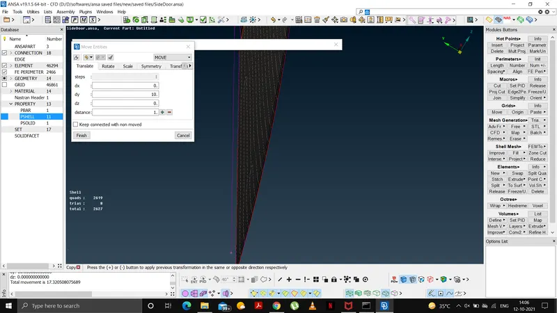
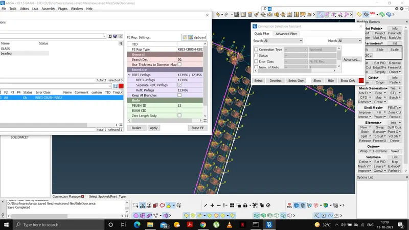
After moving and copying the line, we need to use follwing parameters to realise the spot line-
--FE type- RBE3-CBUSH-RBE3
--DOF-12345
--S(dist btw CBUSH)-10mm
--select appropriate pid's(P1,P2)
--RBE3-PINFLAGS-dof all directions.
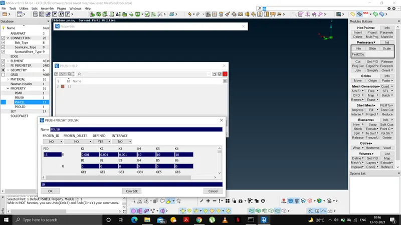
--Then a PID should be created for the PBUSH using "SHIFT+?" from the keyboard.
--Select the new PID and then enter the pre-defined stiffness values as shown below-
--Similarly CBUSH is created on all sides of the glass using appropriate info as shown in figures.
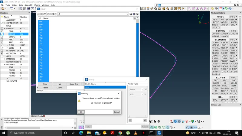
--Finally we orient the CBUSH from database-->CBUSH-->select all-->modify-->name-orient-->modify rules as orient and CID as 0-->OK.
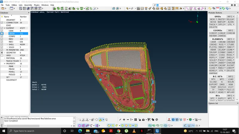
AFTER DEPLOYING ALL NECESSARY CONNECTIONS THIS IS HOW THE REAR DOOR MODEL LOOKS LIKE-
FINAL LOOK OF ALL PID'S CREATED-
- LEARNING OUTCOMES:
We learned-
--How to set PID's for different components of the rear door
--How to give connections for hinges using RBE2 and BOLT JOINTS.
--How to give connections using rigid RBE2 from NASTRAN deck.
--How to give mass to a node at door handles.
--How to deploy a RBE3-HEXA-RBE3 connection.
--How to deploy a RBE3-CBUSH-RBE3 connections.
--How to set appropriate DOF's.
--How to orient the deployed CBUSH altogether.
- CONCLUSION:
We finally deployed all the necessary connections and assigned PID's for the meshed rear door ANSA model.