Week 6 - Creating connection for Rear door
AIM:
To establish appropriate connections between different parts of a given FE-model of Car Door assembly.
OBJECTIVE:
The given model has many parts inside a single assembly model. All these parts does not necessarily have connetions or joints between them.
Quality parameters for these connections have not been given. Random values will be assigned in places needed.
COMPONENT:
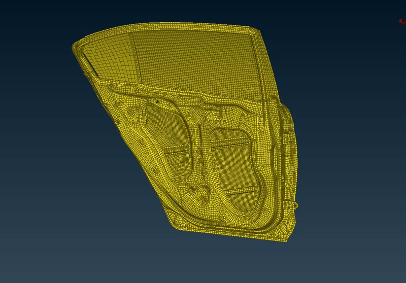
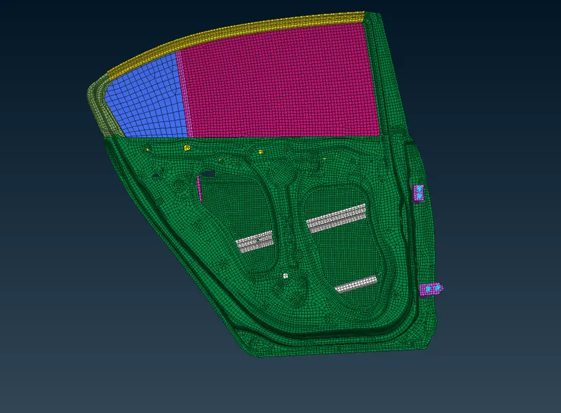
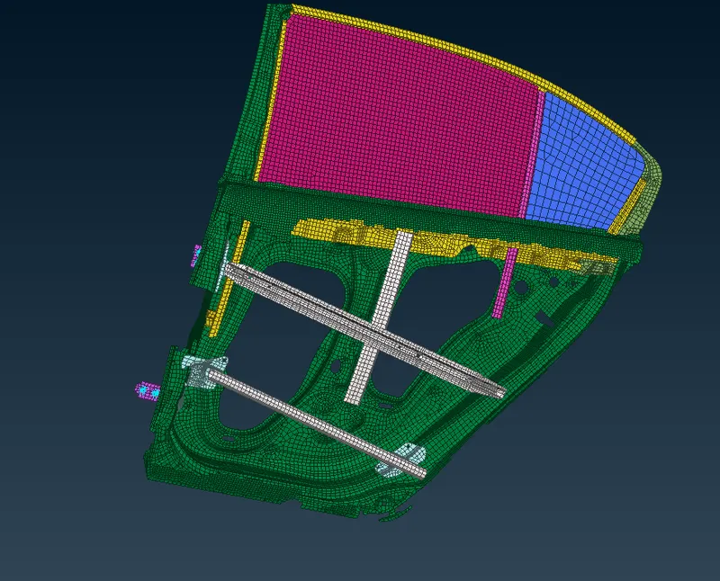
Model has been modified temporarily using different PIDs to give differrent colours for distinguishing different parts of the model. A better perspective or understanding can be obtained from the following images about the given model.
PROCEDURE:
There are different types of connections in a care door model. Some of them are
- Door hinge
- Glass-weather strip connection
- Spotweld connection between different metal parts
- Bolt connections
and many other connections are modelled based on the engineer's perception using different connection types.
1. Connection at the hinges
All the nodes on the edges of the hinge are rigidised using Elements->RBE2->Many nodes in the NASTRAN deck.
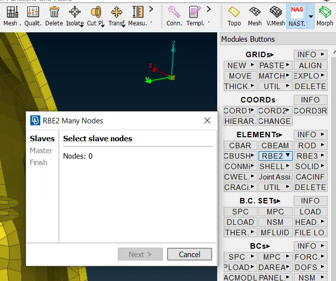
The stem of the hinge is modelled using RBE2->Two nodes.
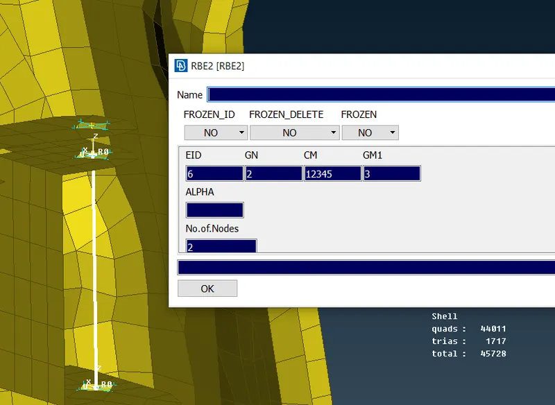
The CM tab represents the restricted Degrees of freedom of the connection. Since the door hinge is allowed to rotate along the z-axis of the model, CM is restricted to only 5 degrees of freedome and not 6.
2. Bolt connection between door frame and hinge supports
Three or four parts/layers are connected together at this connection. ANSA allows for four parts to be defined in a connection.
First, a centre point is obtained using Points->On COG at one of the holes.
Then, this point is converted into a Bolt definition using Assembly->Convert->3d-points->Bolt.
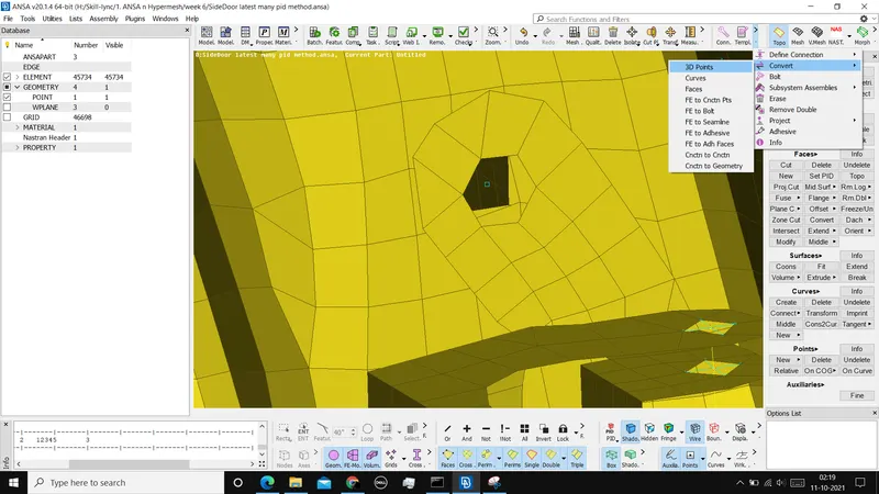
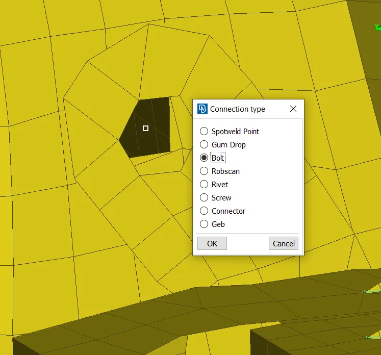
Using Connection selection assistant from the Assembly module, this bolt connection can be defined.
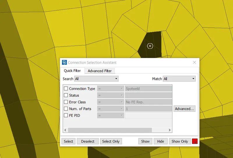
The connection parameters are then defined. They are the parts between whom the connection is established, search distance.
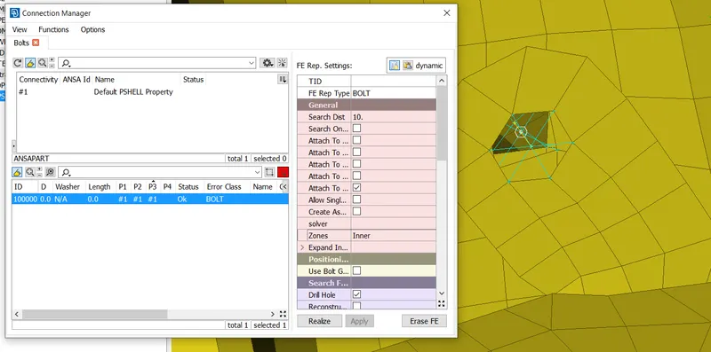
Then, click Apply and realize. A bolt connection is established with RBE2 elements and the stem of the bolt is defined using Two node RBE2.
3. CBUSH connection between Glass and the weather strip
Since there is a damping effect between the Glass and the weather strip holding it, CBUSH elements are used.
First, a connection line is obtained from the glass boundary using Perimeters->Feat2Curve. 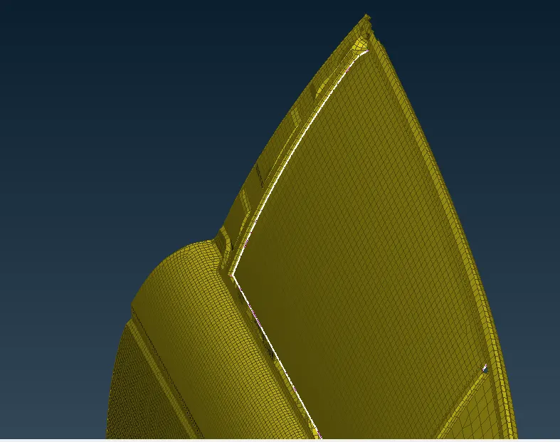
The curve obtained is then converted into spotline definition using Convert->curves. Each curve is converted seperately, as converting them all at once categorizes them under single definition. It is converted into Spotline.
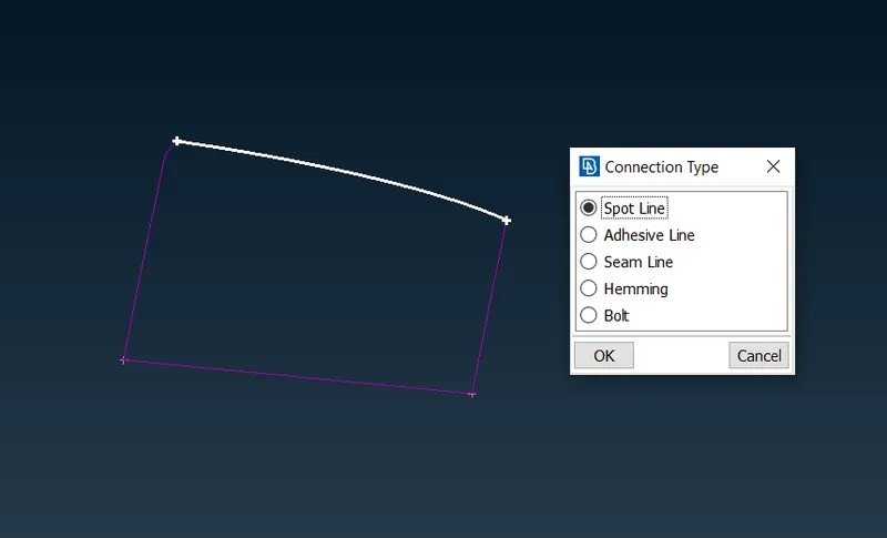
Upon selecting the connection line, details such as two parts and search distance, distance between CBUSH nodes, are defined. The connection FE Rep Type is RBE3-CBUSH-RBE3, Part ID is created.
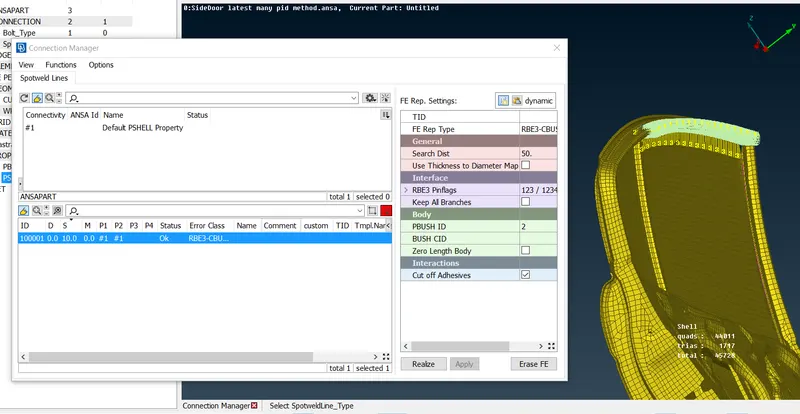
This ID has spring constant values along multiple directions k1-k6. These values are defined from the material of strip. Since the values are not given, random values can be assigned.
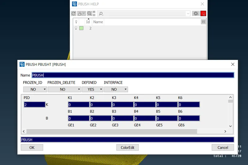
Realizing the connection generates the Cbush elements.
These CBUSH elements can be accessed from the the database window. These CBUSH elements are suggested to have their orientation aligned together. Since their orientation is assigned at random, select all the CBUSH elements from the database window and right click and modify. Create new modification id and under rules, define both orientation and CID(coordinate system ID). Orientation->with cord and assign CID as '0'. Giving 0 as CID aligns the element coordinate system with global coordinate system.
4. Smaller Glass on the door
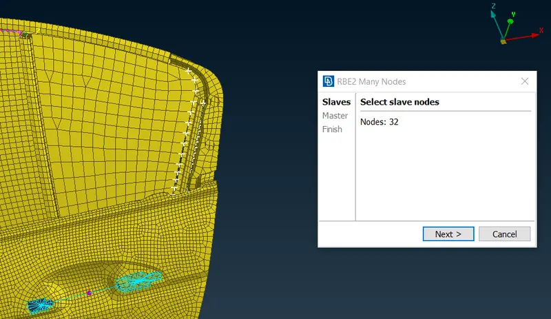
The smaller glass panel on the door is assumed to be rigid at the boundary.
The nodes at the bounary are selected and rigidized using RBE2 elements. The nodes on the weather strip can be selected to establish the connection.
5. Door handle
Door handle is not generally modelled in door model. The nodes on the edges are to be rigidized using RBE2->many nodes.
Then, the Centre node of both these connections are selected and another Many node connection is established. This new centre node acts as the approximate COG of the handle. 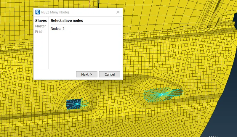
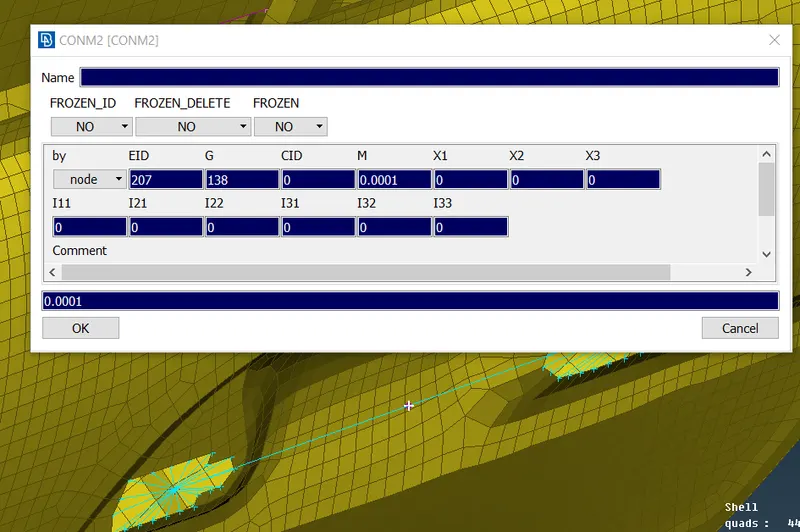
Now, Elements->CONMi->CONM2->Nodes is used to assign concentrated mass of the handle at the new node.
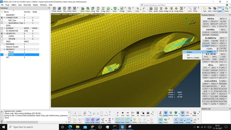
Under the section 'M', mass value is added which is equal to the handle mass. Here, the value input is in Tonnes. So, we have to convert the mass value into tonnes. A value of 100gms is taken here.
6.Connection between glass and the arm that pushes/pulls it
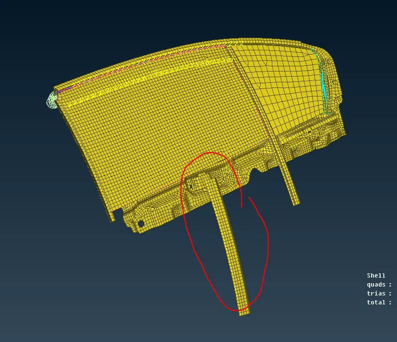
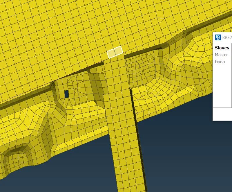
Since the connection type is not properly defined, for FE representation, it is defined as rigid. If the arm does not reach the glass part, these elements are extended upto the glass using Grid->Mv Free. Now, elements adjacent to each other on both the parts are selected and a rigid connection is established using RBE2.
7. Weld connection between two metal parts
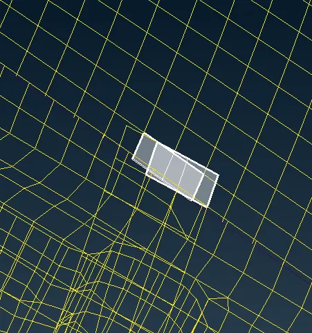
The two parts identified below do not have any bolt connections are adjacent to each other. A spotweld connection is defined between them.
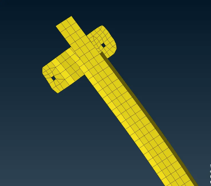
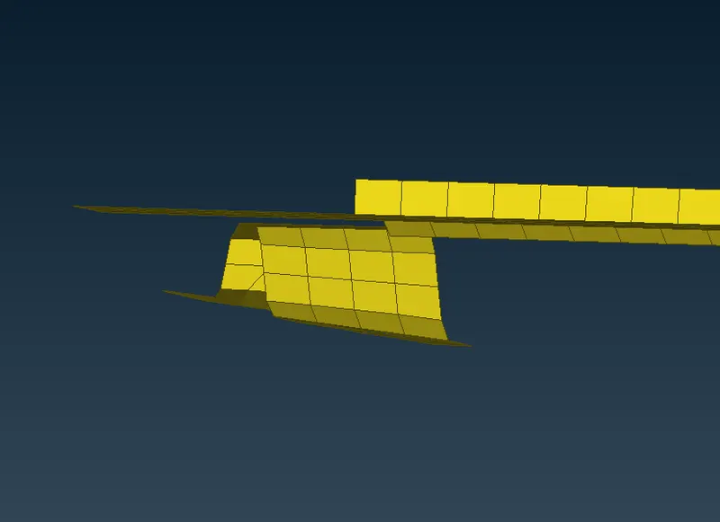
A 3d point is created on one of the parts using Points->On COG. This point is converted into spotweld definition using Convert->3D point.
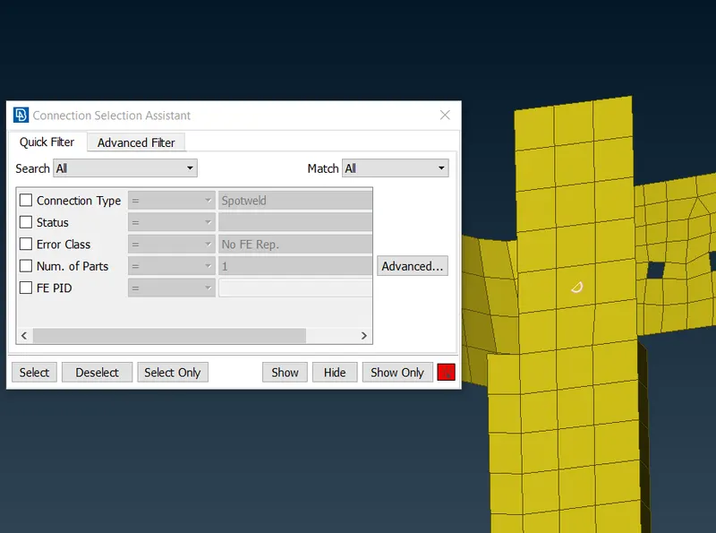
The connection point is selected and the following are defined. Two parts between whom the connection is established, search distance, PID is defined.
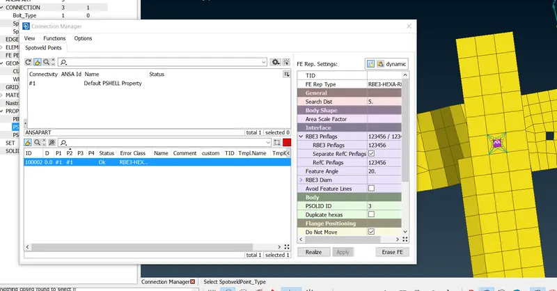
The resulting spotweld connection is formed.
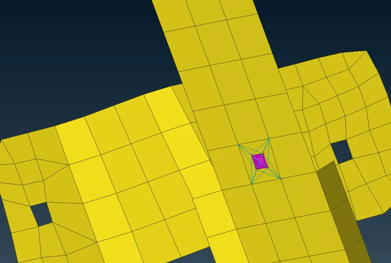
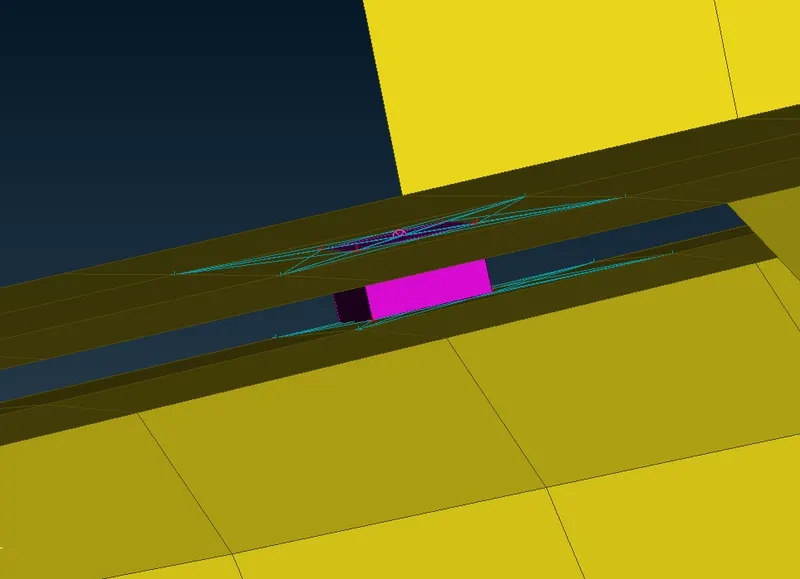
Using these different connection types, many other connections are established between all the parts of the assembly model connecting them.
- Since the geometry of the model is not given, connections established are based on the engineer's perception.
The final result is
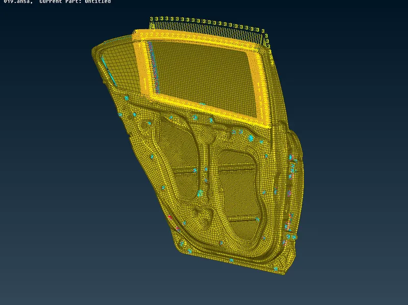
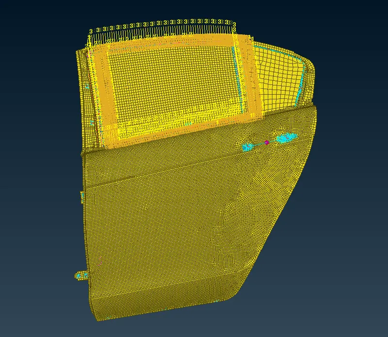
LEARNING OUTCOMES:
- Understood how to perform different types of connection
- Was able to perform connections manually and also using connection manager at places required.
- Have a good understanding of different connections that arise in a given model and was able to define types based on the parts that need to be connected.
CONCLUSION:
The given model with different parts was defined with multiple connections based on the type of connection required. Connection parameters are assigned at random since the values are not given.