Week- 5 - Solid meshing
SOLID MESHING
AIM:
To perform solid meshing of the given rearview mirror model using tetra elements.
OBJECTIVE:
The given model has 4 different parts, each to be defined as seperate volumes for volume meshing.
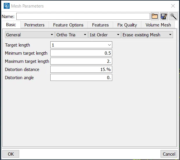
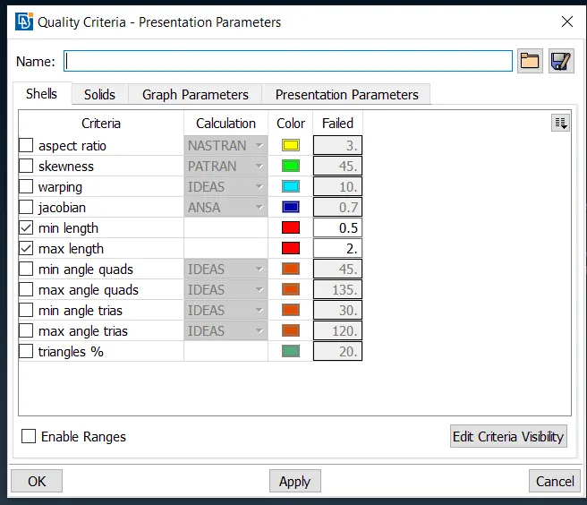
Quality criteria for both shell meshing and volume meshing are
| S.NO | Quality criteria | Value |
| 1 | Target element length | 1 |
| 2 | Minimum length | 0.5 |
| 3 | Maximum length | 2 |
| S.No | Quality criteria | Value |
| 1 | Tet collapse | 0.2 |
COMPONENT
The initial model given has all parts/CONS released.
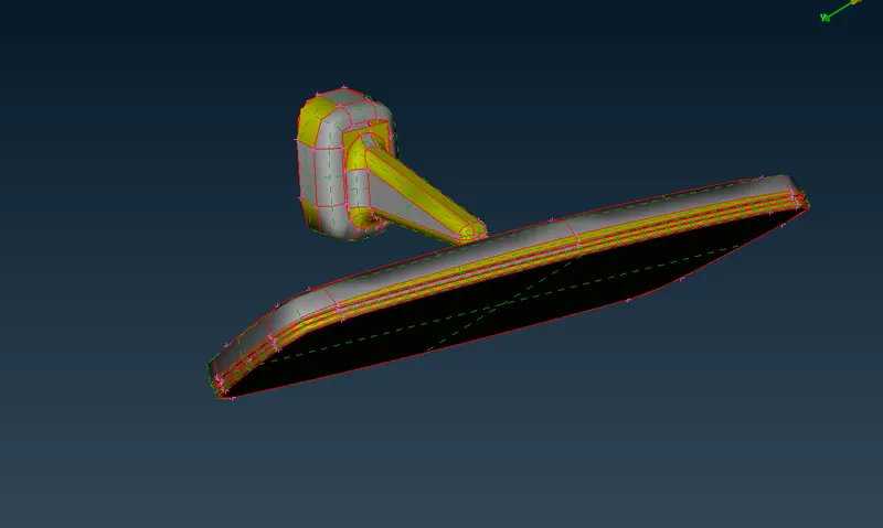
Since the boundaries of each entity is not rendered properly, the model seemed to have lot of empty spaces.
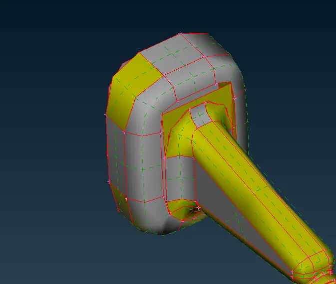
performing Fine option on each of them will turn them back to normal. Or Perimeters->Length can be used to set the node length as 1 unit, which will also refine the boundaries.
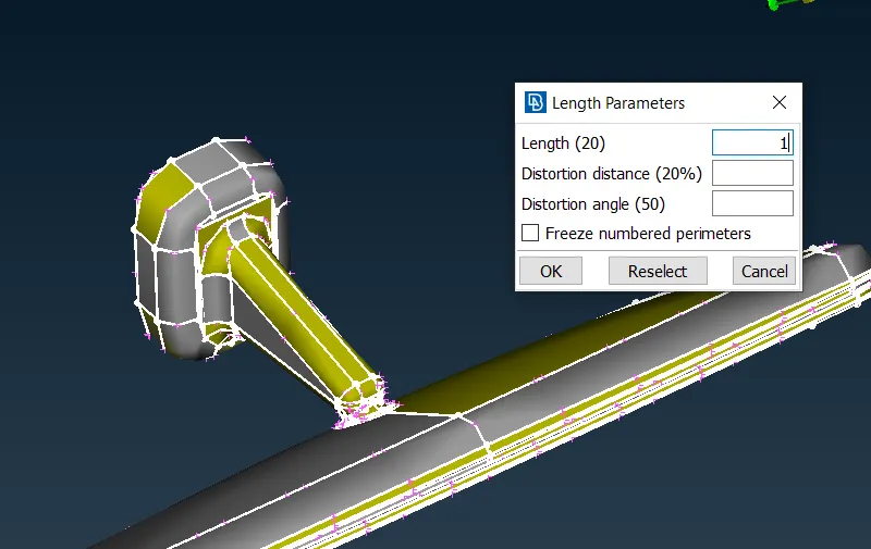
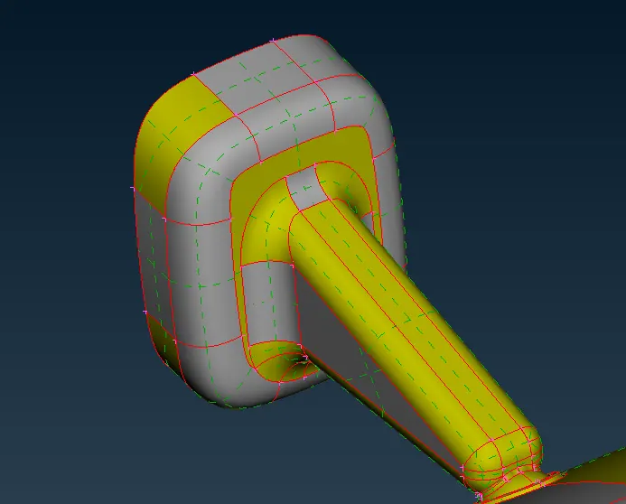
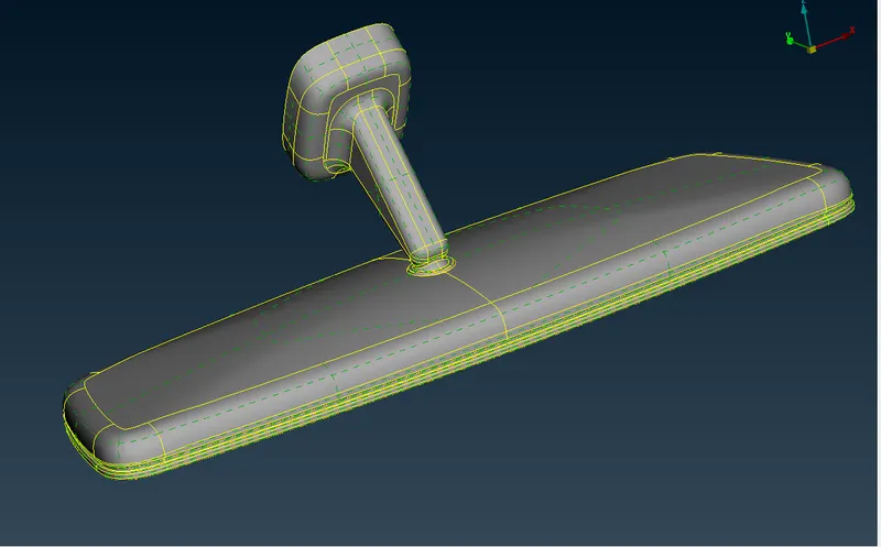
In order to stitch them back together, Topo can be performed. But since the model has four different parts in an assembly closely spaced, performing topo can make the CONS close to each other stitch together, even though they may belong to different parts.
It is therefore necessary to seperate the parts and then perform Topo on each part seperately.
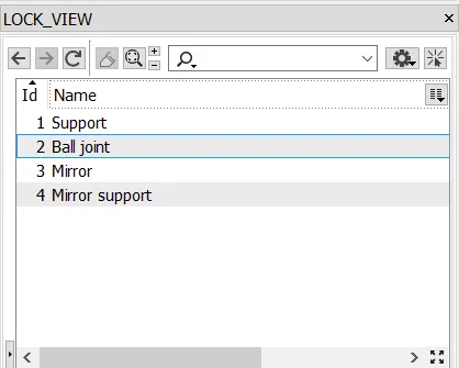
Different parts of the model can be managed easily by creating lockviews of the model.
Now, the peoper mode after performing Topo is
PROCEDURE:
Geometry cleanup
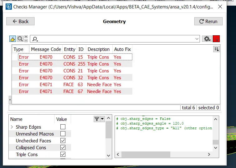
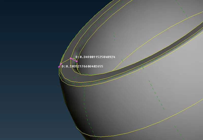
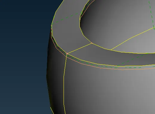
The geometrical errors in the model should be checked and fixed using Checks->Geometry.
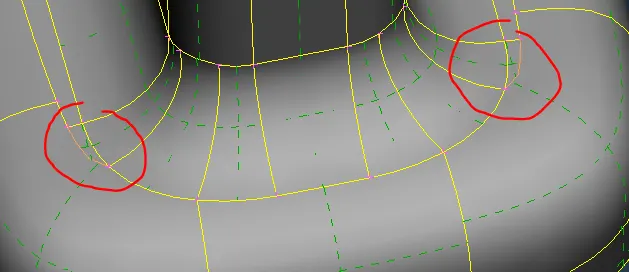
Many of the fillets these parts will not pass the minimum element length criteria unless they are suppressed, removed using Faces->Dach or converted to Chamfers.
2.Shell meshing
All four parts of the model has to meshed. Mesh and Quality parameters are input.
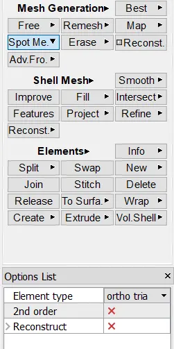
Meshing can be done using Spot mesh and Reconstruct while toggling between Ortho tria and tria in the options list.
Tria meshing has two options- tria and ortho tria. Curved surfaces are meshed using ortho tria meshing as these elements capture the features better. Planar surfaces and curved surfaces with little curvature are meshed with regular tria elements.
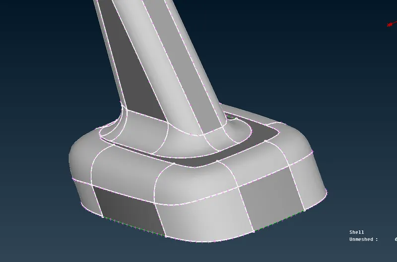
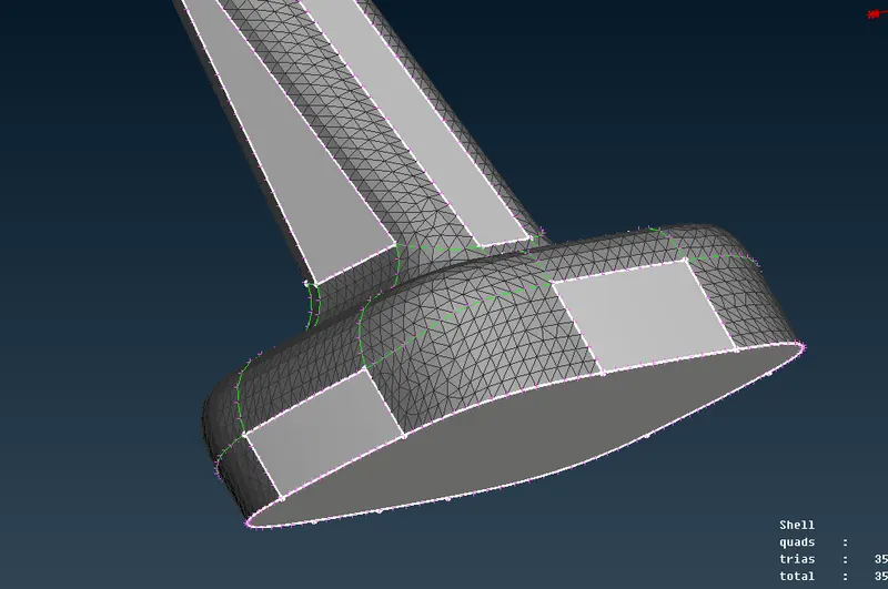
All the off elements can be rectified using Smooth, Num+/-, Cut and others.
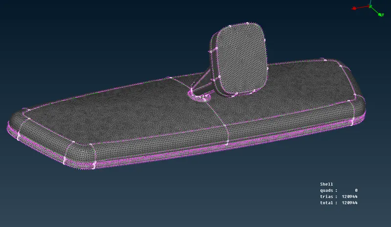
The final shell meshed model after avoiding all OFF elements is
3.Volume meshing
For volume meshing, first volume has to be defined for each part. All four parts volumes are defined seperately.
Volumes->Define->Manual and select the entity/part and it has to be a closed volume. All the defined volumes appear in List tab.
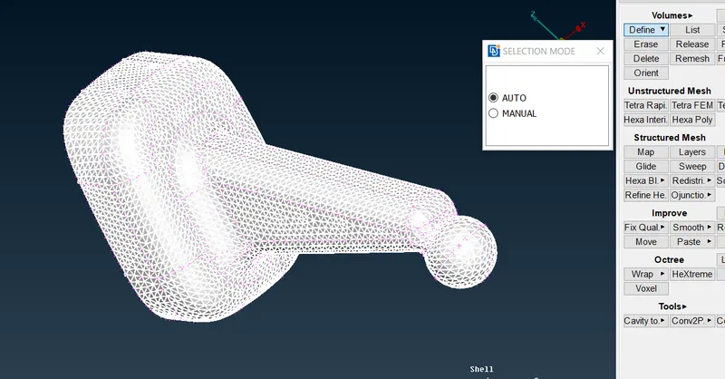
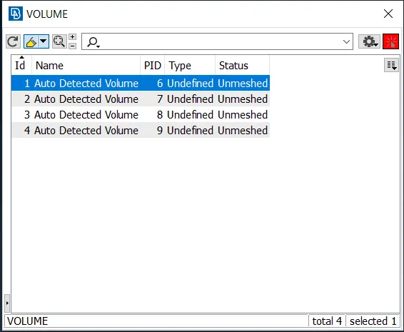
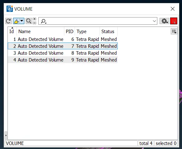
The mesh type need to be updated to Tetra Rapid/FEM. Any one is fine in this case. And for mesh status, right click and select remesh option.
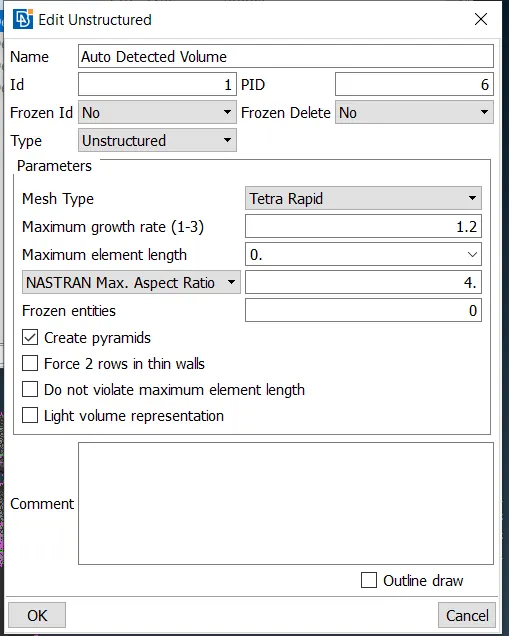
This volumes defined should be assigned PID and MIDs completely different from the ones already existing. When the volume is defined, PSOLID property card is generated automatically.
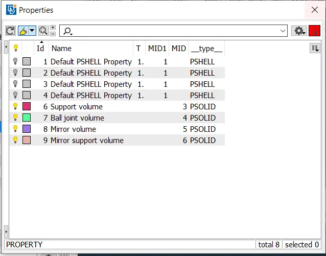
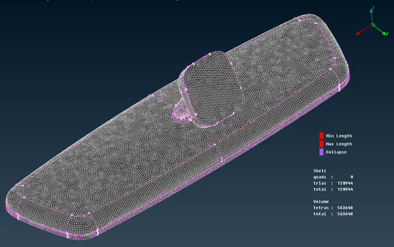
The volume mesh should be generated for each part individually and any off elements can be rectified using Mv Free for nodes of off elements.
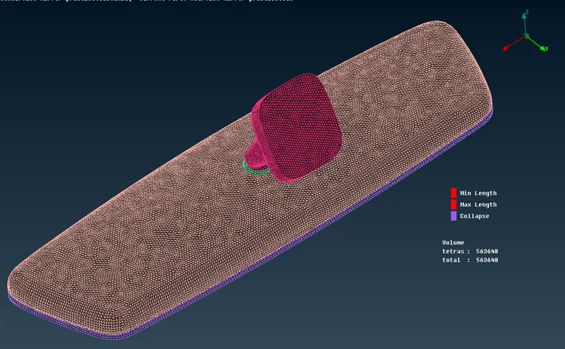
The final result is
Turning off the visibility of geometry entities, Volume mesh is visible in it's assigned colour and can be observed clearly.
LEARNING OUTCOMES:
- Learned how to perform volume meshing.
- Understood the differences in Tetra Rapid and Tetra FEM mesh.
- Was able to perform meshing using Batch mesh.
CONCLUSION:
The given model was meshed seperaely for each part to avoid interfering of mesh elements of different parts. And the OFF elements for both shell meshing and volume meshing were solved/avoided using different techniques.