Week 3 - 2D meshing for sheet metal
HOOD MODEL PRE-PROCESSING USING ANSA
AIM:
To perform geometry cleanup, extract midsurface and mesh the given hood component with given quality parameters.
OBJECTIVE:
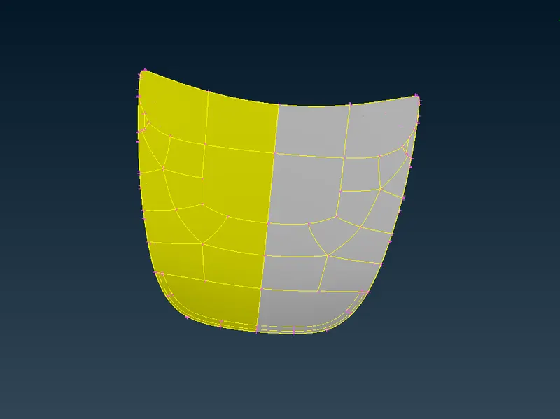
The CAD model of the hood component has five parts-
Outer panel, inner panel, two hinges and a latch.
Perform geometry cleanup of these components to avoid topological errors. Extract mid-surface of the components and perform mesh generation with a target length of 5mm. Improve mesh so that the given quality parameters are satisfies.
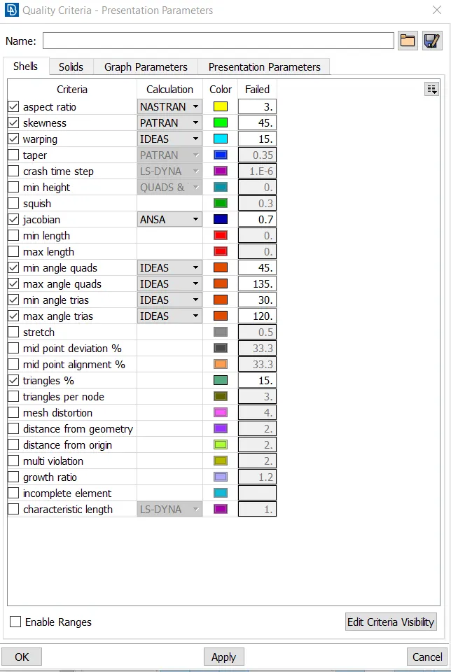
| Sr. No | Quality Criteria | Value |
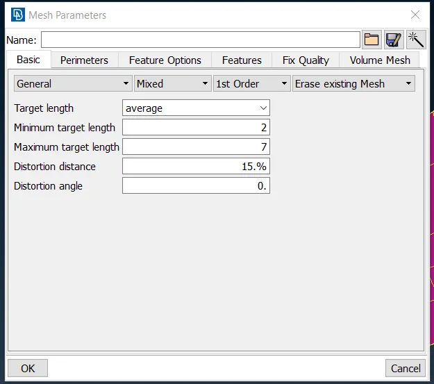
| 1 | Target/average length | 5 |
| 2 | Minimum length | 2 |
| 3 | Maximum length | 7 |
| 4 | Aspect | 3 |
| 5 | Warpage | 15 |
| 6 | Skewness | 45 |
| 7 | Jacobian | 0.7 |
| 8 | Min. Quad angle | 45 |
| 9 | Max. Quad angle | 135 |
| 10 | Min. Tria angle | 30 |
| 11 | Max. tria angle | 120 |
| 12 | Tria percentage | 15 |
Component-
PROCEDURE:
1.Geometry Cleanup
Importing the geometry into ANSA may result in many topological errors. First, perform check using Checks->Geometry and the errors can be fixed using Fix option or manually using different topological options.
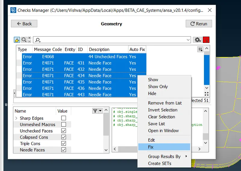
geometry cleanup needs to be performed until the Check geometry execution gives 100%.
2.Lock view and measurements
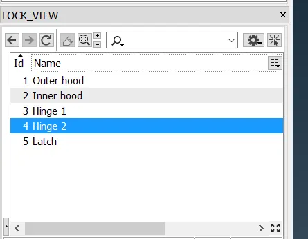
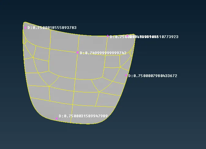
The model consists of 5 components. Orientation of these components can be adjusted using Orient option. Store lock option can be used to lock different views for easy access. Component's thickness has been measured using Measure tool. Each component's thickness are observed to be 0.75mm(Outer and inner panel) and 1.2mm(Hinge and latch).
3.Generating mid-surface
When a model has same features troughtout the thickness, these models can be represented using the mid-surface to reduce the computation time without losing accuracy in results. Mid-surface can be generated using two methods
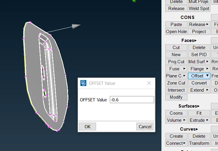
1)Using offset on each surface individually or as a batch giving offset value half of thickness measured. Direction of offset needs to be kept in mind. Then all these mid-surfaces can be stitched together using topo option.
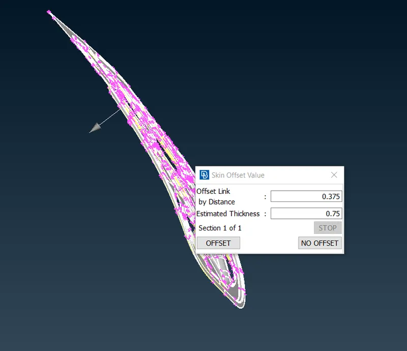
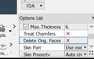
2)Mid-surface option generates mid-surface of a closed volume automatically. Any errors arising can be resolved using methods used in geometry cleanup. Delete faces option must be unchecked in the Options list at the bottom right of the screen, otherwise the shell model will be deleted.
- Offset option has been used for Outer panel and hinge and latch components because of simpler geometry and ease of generation.
- Mid-surfacing using skin option has been used for Inner panel because of it's complex geometry with many faces and features and difficulty using offset option.
After generating mid-surfaces, it is best to store locks of the mid-surfaces as well for easy access.
Each mid-surface has to be assigned PID. This can be done using Set PID option. Surfaces needs to selected and then right cock the list and go to NEW -> PSHELL->PSHELL. Assigning ID for easy maintenance and thickness equal to thickness of the original component can be done using edit option.
4.Assigning quality criteria
Preparation for meshing includes giving Mesh parameters and Quality Criteria using the given values.
5.Element generation and defeaturing
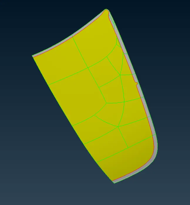
Then, the target element length can be generated using Length tool in Mesh module. It can be observed that both outer panel and inner panel are symmetrical along mid-plane. So, half of the geometry can be taken for meshing using delete faces option and can be transformed later to obtain full component.
Defeaturing needs to performed at certain locations like corners, bends and miniature features, for example heming region of outer panel, where element length fails to fall under the acceptable range without losing too much of the feature.
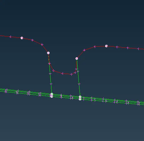
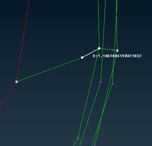
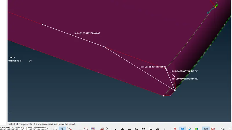
Various options like
Hotpoints->Insert
Perimeters->Num+/-
Macros->Cut can be used while defeaturing to make sure that element length falls in the acceptable range.
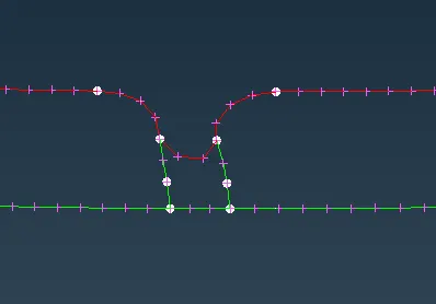
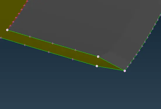
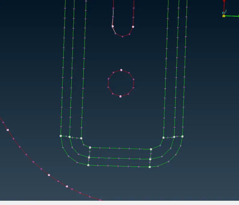
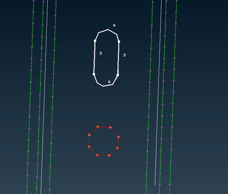
Also, at holes, make sure the number of elements are even in number and the nearest element is parallel to closest perimeter using Perimeters->Slide and mark the new position with Hot points->Mark/un
6.Meshing and mesh improvement
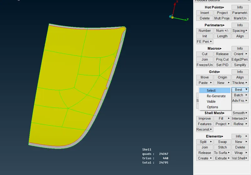
Now, for meshing, Mesh Generation->Best option generates best possible mesh.
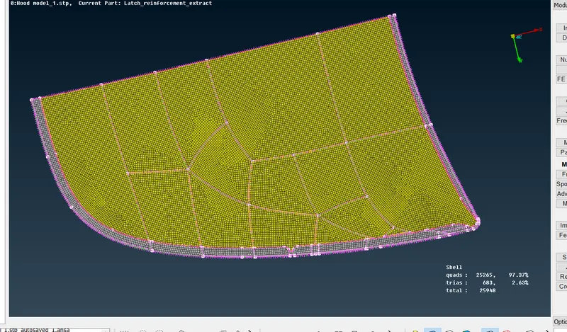
Auxiliaries->Hidden option shows the mesh elements which are failing the given quality criteria. Elements are coloured differently for different criteria and right click->show only can be used to highlight the regions and find the location.
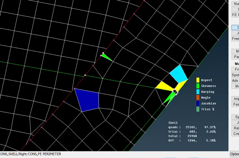
These faults can be rectified using options like
Perimeters->Num+/-, Shell mesh->Reconstruct, Shell mesh->Smooth, Elements->Split, Macros->Cut, Hot points->Insert until the number of OFF elements in the table becomes '0'.
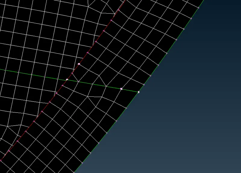
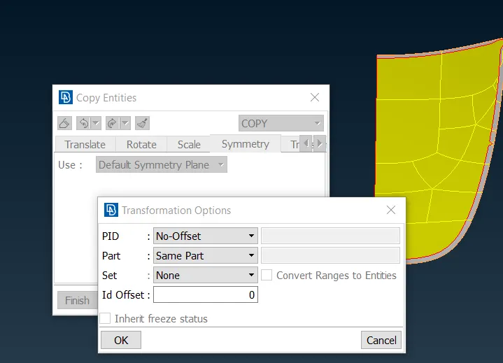
As the off elements are avoided and the best possible mesh based on perception is obtained, the half model can be copied using Transform->Copy->Symmetry
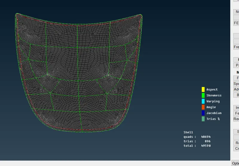
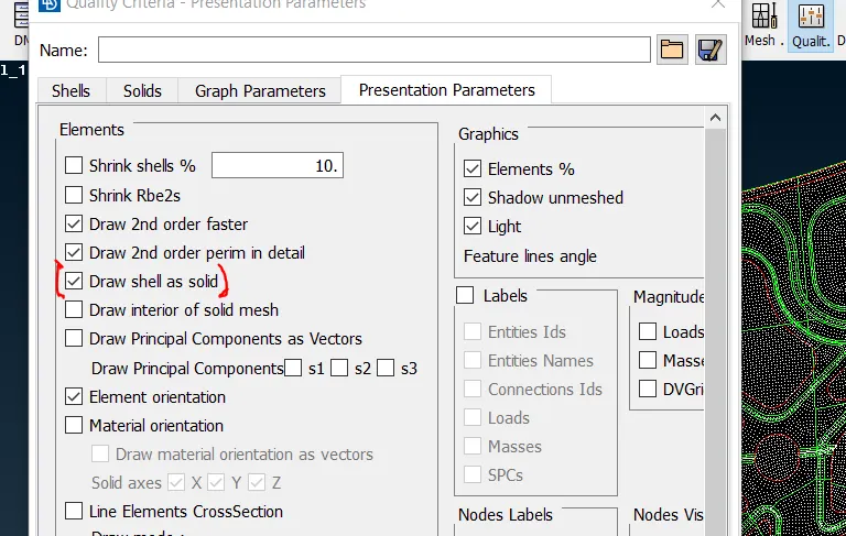
Finally, after the final meshing is done, go to Quality Parameters->Presentation parameters and check the Draw shell as solid option.
 .
.
All Meshed Components:
1)Outer Panel

2)Inner Panel
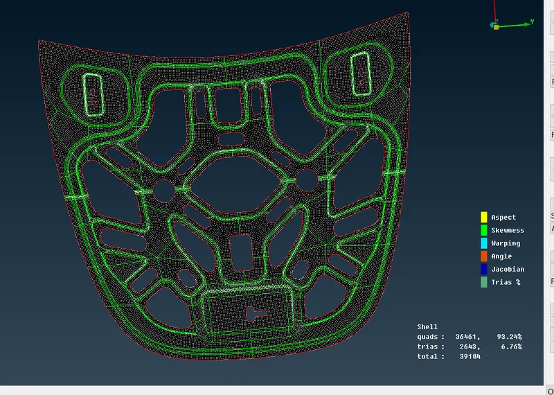
3)Hinge Reinforcement
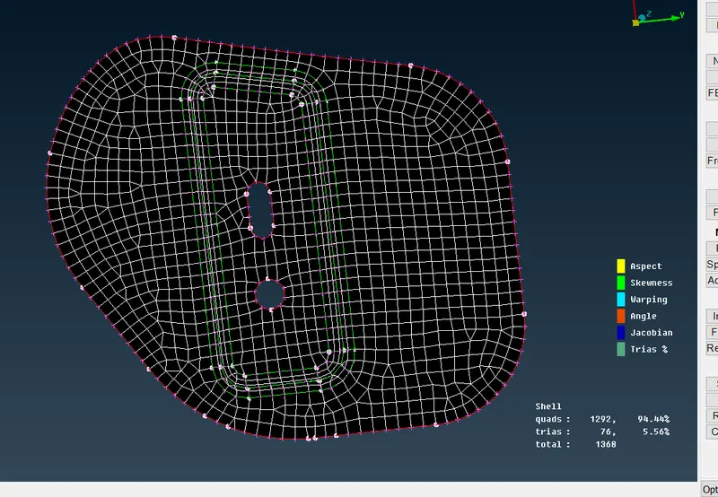
4)Latch Reinforcement
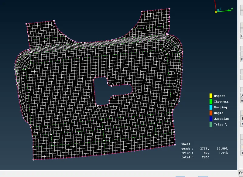
Full Assembly:
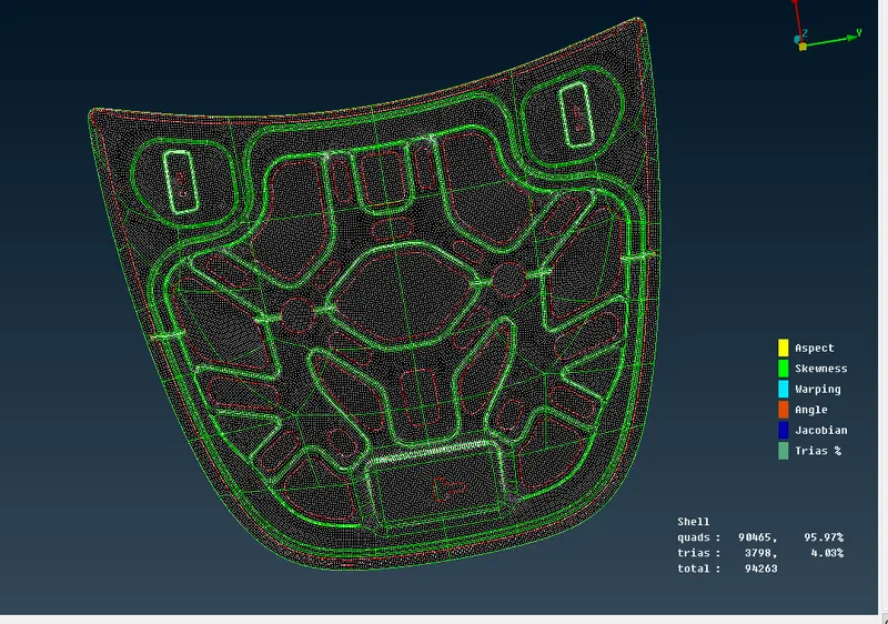
The Tria percentage is 4.03% which is well within the limit of 15%.
LEARNING OUTCOME:
- Better understanding of different tools/options in ANSA interface.
- Able to perform geometry cleanup and mid-surfacing techniques for complex geometries.
- Able to perform Mesh Generation and Mesh improvement to generate mesh with good flow according to the required quality parameters.
CONCLUSION:
The given component was meshed and improved as per the quality parameters by following the proper order of geometry cleanup, mid-surface generation, mesh generation and mesh improvements using right techniques suggested. The final model has no off-elements and element length is under acceptable range.