Week - 4 - 2D meshing for Plastic components
2D MESHING OF PLASTIC BOTTLE CAP
AIM:
To perform manual midsurfacing of given bottle cap model and mesh the model with given quality parameters.
OBJECTIVE:
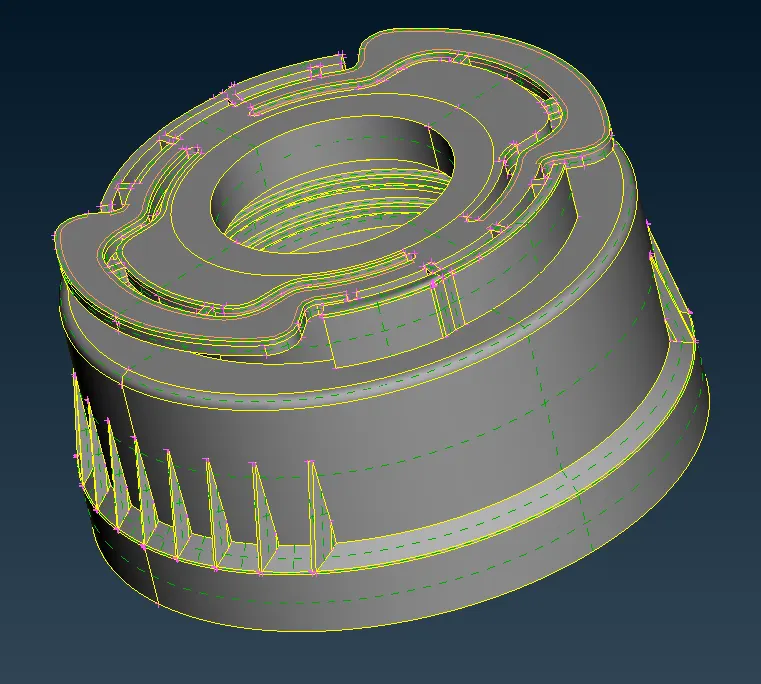
The given bottle cap model has various features like teeth, ribs and threads of various thickness. Take midsurface of the model using different methods, different tools/options and mesh the component.
| Sr. No | Quality Criteria | Value |
| 1 | target/average length | 1 |
| 2 | Minimum length | 0.5 |
| 3 | Maximum length | 3 |
| 4 | Aspect | 3 |
| 5 | Warpage | 15 |
| 6 | Skewness | 45 |
| 7 | Jacobian | 0.7 |
| 8 | Minimum Quad angle | 45 |
| 9 | Maximum Quad angle | 135 |
| 10 | Minimum Tria angle | 30 |
| 11 | Maximum Tria angle | 120 |
| 12 | Tria percentage | 15 |
Component-
PROCEDURE:
1.Lock views and Geometry cleanup
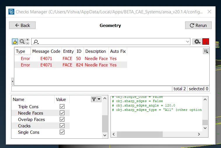
The gemoetrical errors in the model resulting from importing into ANSA should be checked using Checks->Geometry and they can fixed using Auto Fix.
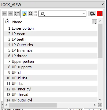
Different parts/features of the model can be managed easily by creating lockviews of smaller components/sections of the model.
LP indicates Lower portion and UP Upper portion
Many of the features/Cons lines that these parts have can be suppressed/removed without affecting the geometry, so that managing them and creating mid-surfacing will become easier.
Below is an example of how clean the geometry can be made to extract midsurface of the part.
- The lower half of the given model without all the ribs, threads and teeth is taken and released from remaining model using CONS->Release and Faces->Topo.
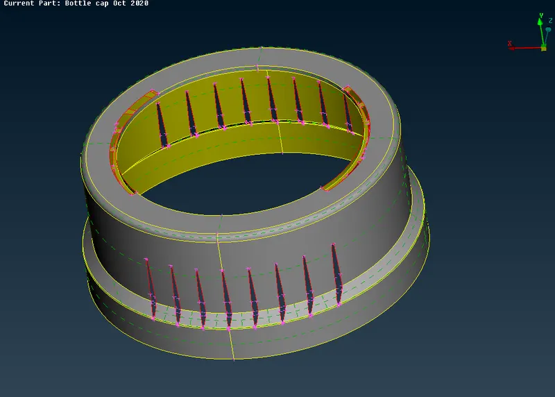
- The model then can be made clean by fillling the gaps and removing unnecessary features and removing CONS lines using options like Faces->New, Faces->Modify, Hot points->Insert, Hot points->Project, CONS->Project, Faces->Project cut, Faces->Dach, Curves funstions
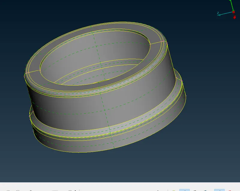
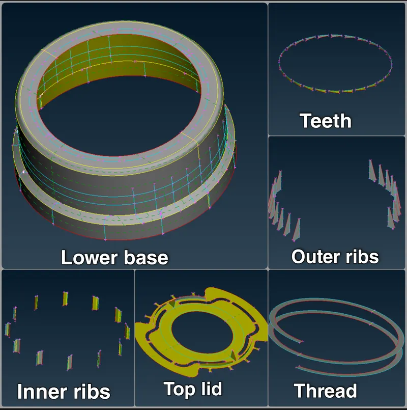
All the parts in different lock views have released and seperated for easy manipulation from the parent geometry so as to not affect the parent model while doing geometry cleanup.
The model has been seperated into following parts
| Lower portion | Upper portion |
| Base surface/cylinder | Top lid |
| Outer ribs | Supports |
| Inner ribs | Outer and inner cylinder |
| Teeth | ribs |
| Thread | Thread |
2.Mid-surface generation
Since model is divided into smaller sections, it is easier to generate mid-surface for each of them seperately.
Options Faces->Offset, Faces->Middle, Curves->Middle, Curves->Create, Surfaces->Extrude, Points->On COG, Curves->Tangent etc have been used to obtain the mid-surfaces of each component.
For features like teeth, thread, methods were employed to obtain mid-surface.
- For teeth, two types of midsurface can be obtaied. Along the thickness of the teeth and other is by taking middle vertically. Best version of mid-surface is based on the perception of the engineer, so that after using Draw shell as solid option, the model they obtain is the best for further analysis.
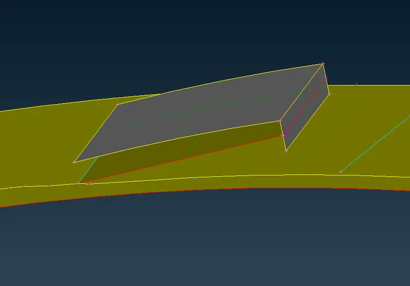
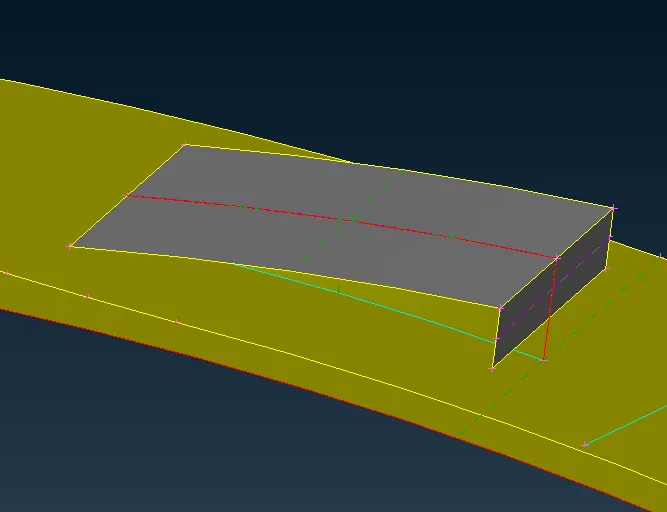
- For thread, Faces->Dach option is used on the edges of the thread. Then Curve->Middle option is used on the thread and the obtained curve is projected on the base and Faces->New is used to obtain the mid-surface.
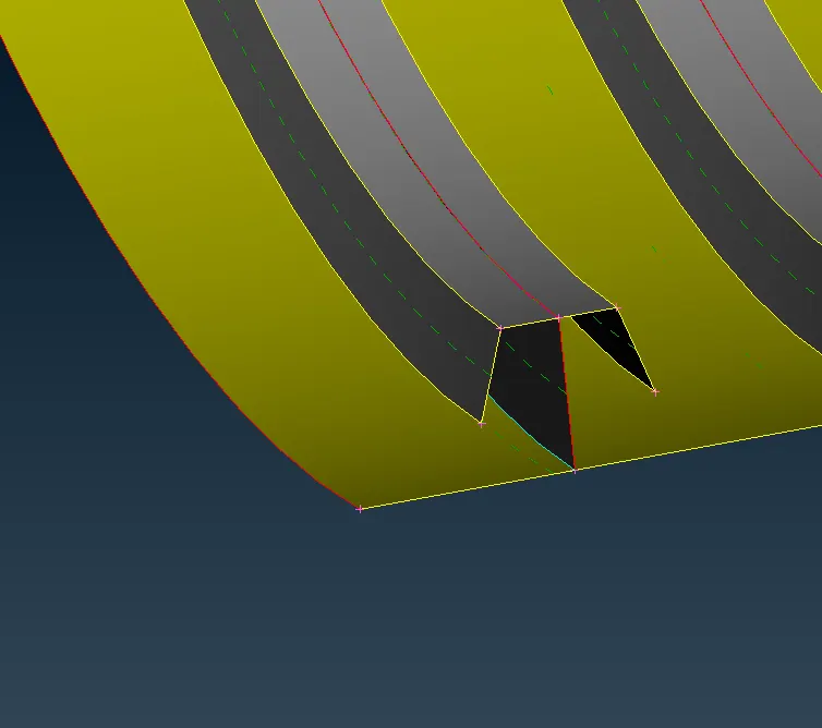
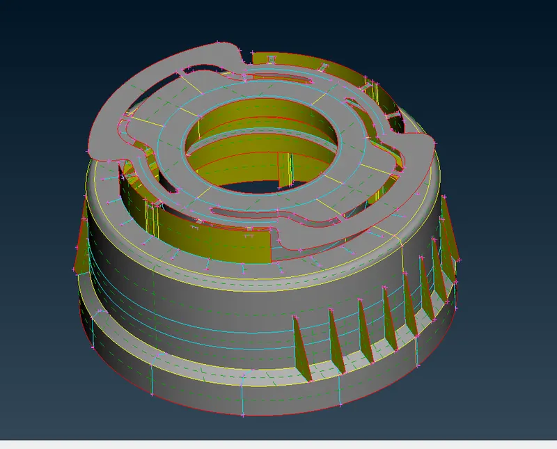
After obtaining all the mid-surfaces seperately, they can be merged together using Faces->Topo. All the spaces can be filled and faces can be connected with Faces->Extend, and Faces->Intersect.
3.Set PID and assign thickness
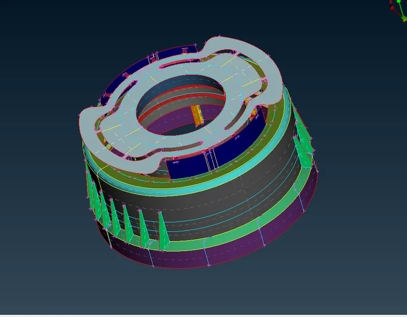
Mid-surface for each lockview has been created seperatedly so as to assign thickness properly, since model has various thickness values.
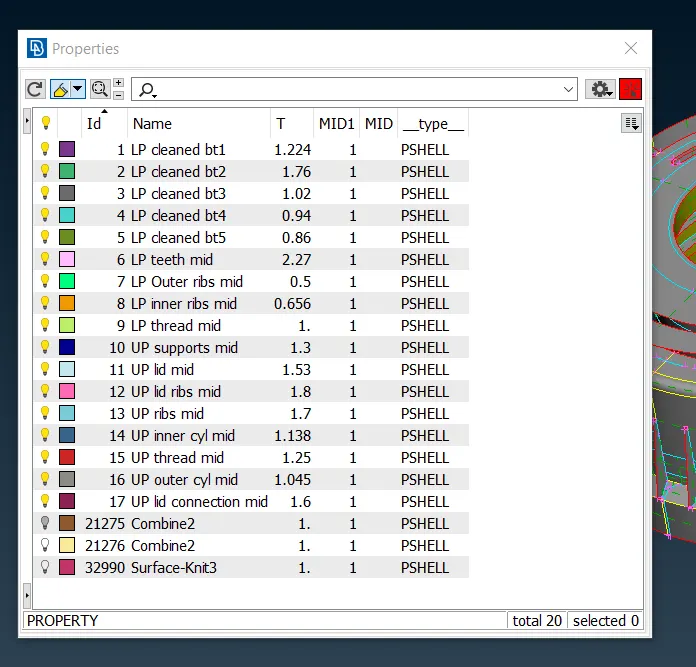
- For features with varying thickness like ribs and thread, all the thickness values along the mid-surface has to measured and average value can be assigned.
4.Meshing
For meshing, mesh parameters and quality parameters have been assigned.
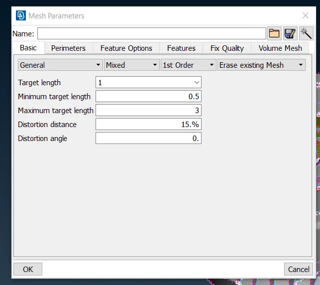
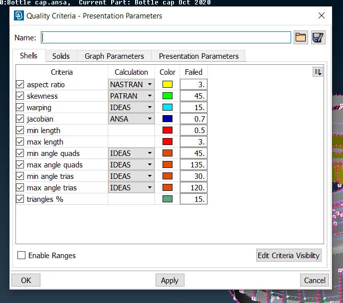
Target element length of 1 unit on the perimeters has been generated using Perimeters->Length.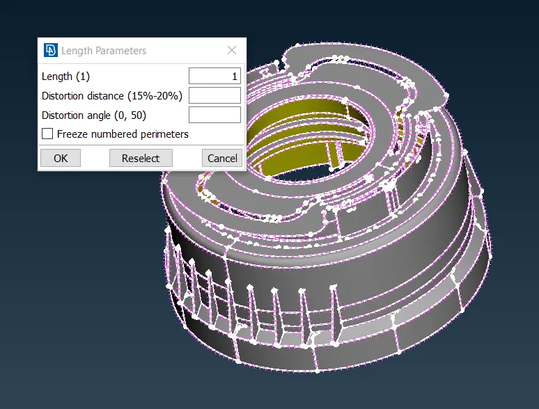
Mesh is generated using Mesh Generation->Best. The elements failing quality criteria can be viewed using Auxiliaries->Hidden mode.
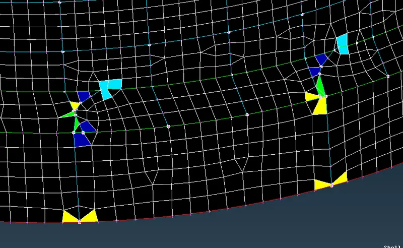
These faults can be rectified using options like Perimeters->Num+/-, Shell mesh->Reconstruct, Shell mesh->Smooth, Elements->Split, Macros->Cut, Hot points->Insert to reduce the number of OFF elements.
- The Triple CONS in the model resulting from various features makes it so that there are some OFF elements which cannot be removed unless further defeaturing of the model is done. So, as to not lose the features, those mesh elements have been left as it is.
Meshed component:
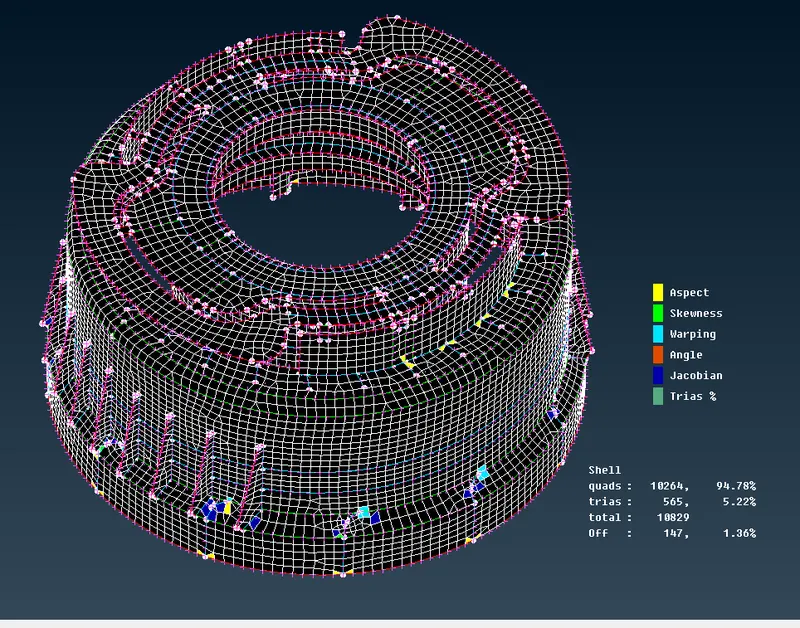
The tria percentage is well within the 15% limit.
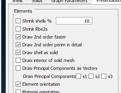
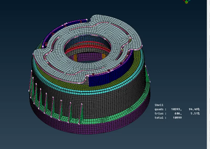
Now, check mid-surface model with parent model to see thickness using Quality parameters->Presentation parameters and check Draw shell as solid option.
The final rsult obtained is
LEARNING OUTCOME:
- Have a better understading of geometry cleanup and meshing techniques.
- Well versed with many options/tools and how to use them for faster and better results.
CONCLUSION:
The given component was meshed and improved as per the quality parameters by following the proper order of geometry cleanup, mid-surface generation, mesh generation and mesh improvements using right techniques suggested. The final model's target element length is under acceptable range. The OFF elements resulting from Triple CONS in the model have been left as it is, as further improvement leads to defeaturing of the model.