Week 6 - Creating connection for Rear door
AIM
The project aims to establish the required connection on the rear door. The project aims for preparing the model for the NVH simulations.
Procedure
Once the model is imported into the Ansa the model is checked for geometry clean up since we are preparing the model for simulation the model has meshed already. To create a connection between the subsystem, the model should be assigned with different PIDs to visualize where the connection is required and shown in the below figure. To create a connection in the systems, an NVH deck module is used.
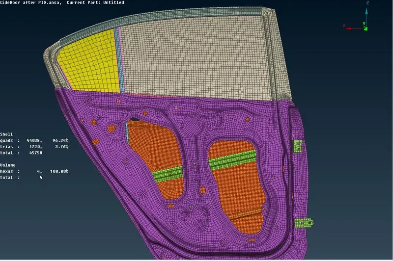
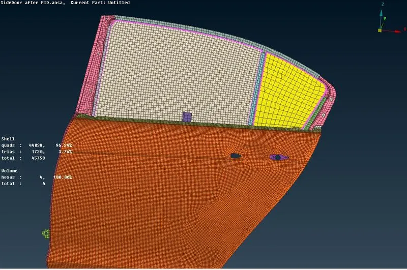
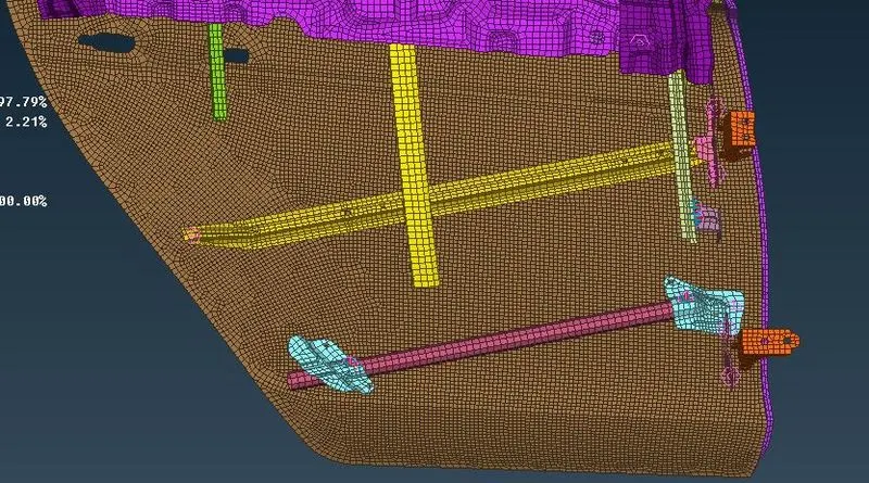
There are different connections available on the model such as nut & bolt, seam welding, spot welding, bush and mass connections. It is important to analyse such parameters and a proper connection should be established.
Moving onto the model, on the right side of the door we have a hinge part that helps to open and close the car door. The connection in such a system is established by using RBE2 elements. In RBE2 elements many nodes are selected and on the confirmation, the connection is established on the hole and shown in the below figure. The nodes on the element are called slave node and the node which connects to the slave node is called the master node. Since this connection is rigid the degree of freedom is arrested in all linear translation and linear rotation movements.
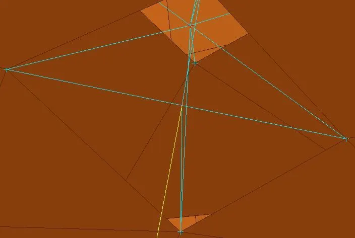
Between the two rigid holes, hinge representation should be done which ensures the passenger open or close the door. Since there is a linear rotation on the z-axis, to represent the hinge representation RBE2 two node elements is used by selecting the two master nodes on the rigid connections and the degree of freedom should be arrested in all directions except linear rotation movements on the z-axis and shown in the figure.
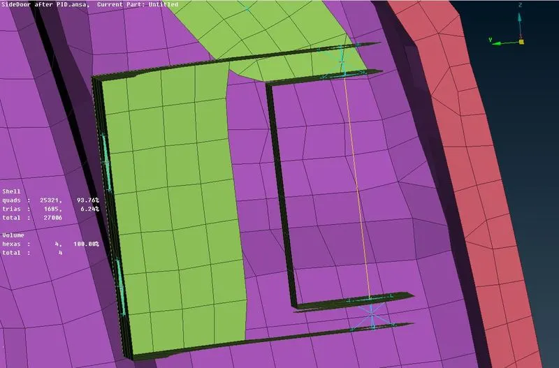
Since the hinge plate is connected to the other plate, the connection between the two plates should be done. By using RBE2 elements, the nodes of each plate are captured and a cluster connection is made and shown in the figure.
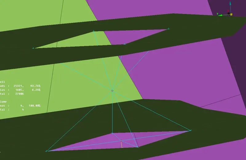
Since the hinge plate is attached to the door inner panel the rigid connections should be provided between the subsystems (subparts). To create the rigid connections, a COG point is generated in the middle of the hole. The 3D point is then converted into a bolt, then all the parts have to be specified which are connected by bolts, and the search distance should be provided to establish the connection. In the zone IN/OUTX is selected and on realizing the bolt connection is established between the parts and shown in the below figure.
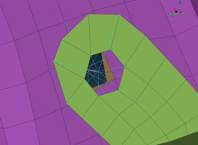
The same procedure is applied to another hinge part on the rear door and shown in the figure.
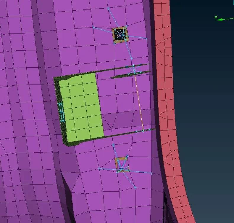
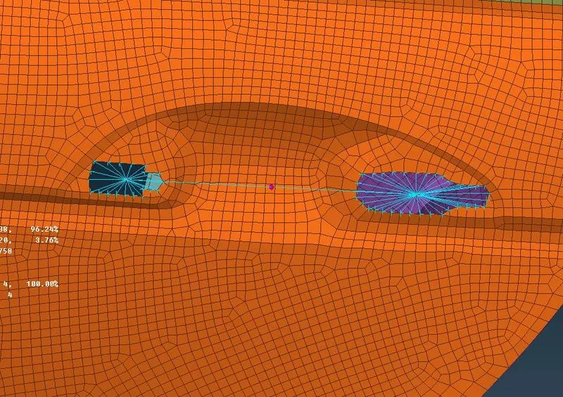
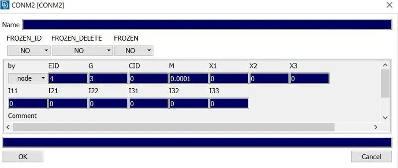
On moving onto the door handle, the mass element should be represented on the door handle. On the holes, RBE2 elements are established by using many nodes. Another RBE2 element is established by selecting the two master nodes. At this node, the mass has to defined by selecting CONMI and the weight of the door handle should be converted to a tonne and the value is provided in the mass section. The representation and provided mass in terms of a tonne is shown in the figure.
Moving onto the subsystems inside the door panel, the necessary connections are established. The part given in the below figure is spot-welded to the next subsystem. To provide a spotweld connection, the COG point is created at the centre of the element. Then this 3D point is converted into the spotweld point. By selecting this spotweld point on the connection manager, the spot weld representation can be done. in connections manager, it is important to specify the two parts which are welded together and FE representation for spot weld is RBE3-HEXA-RBE3 is chosen. Furthermore, the search distance should be given to capture the spot weld and the degree of freedom for RBE3 pinflags should be arrested in all linear translation and rotational directions. The new solid id is created for the spotweld and on realising the spotweld connection is created between the two parts and shown in the figure.
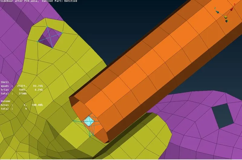
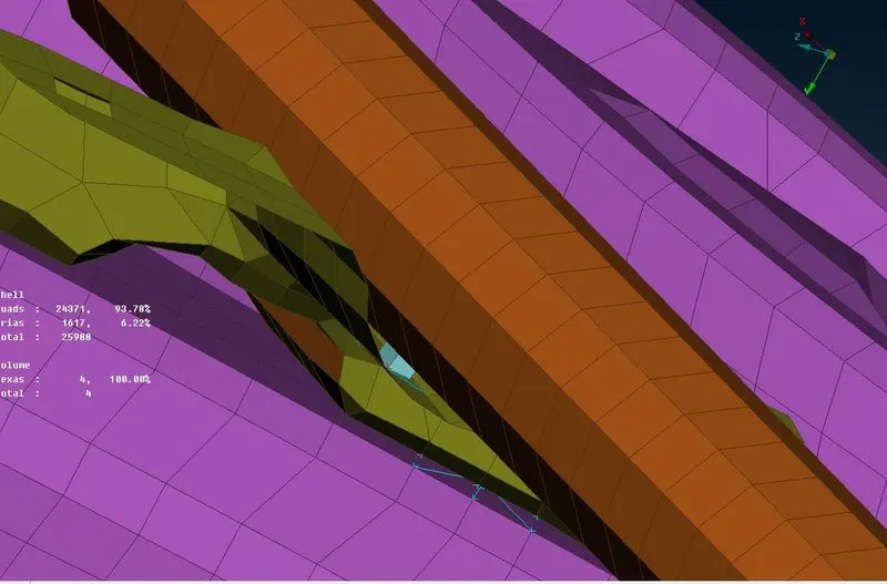
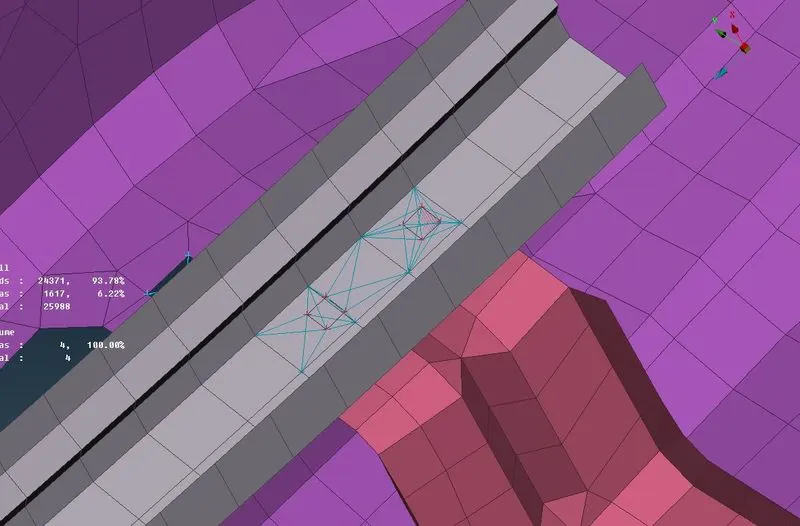
The spotweld is created by RBE3 elements, in which the slave node is formed in the centre and all other nodes are master dependent node whereas in the RBE2 element master node is represented in the centre and the slave node forming a spider with a master node. The same procedure is carried for the other parts which are spot-welded together.
The RBE2 connection is established when the parts are connected by bolts or to represent the rigid connections between two parts. Inside the door panel, many parts are established by an RBE2 connection and shown in the below figure.
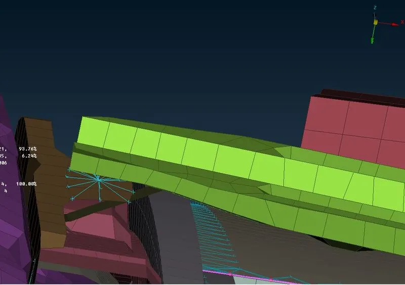
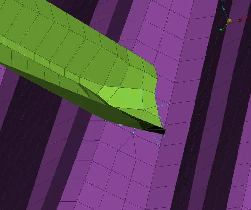
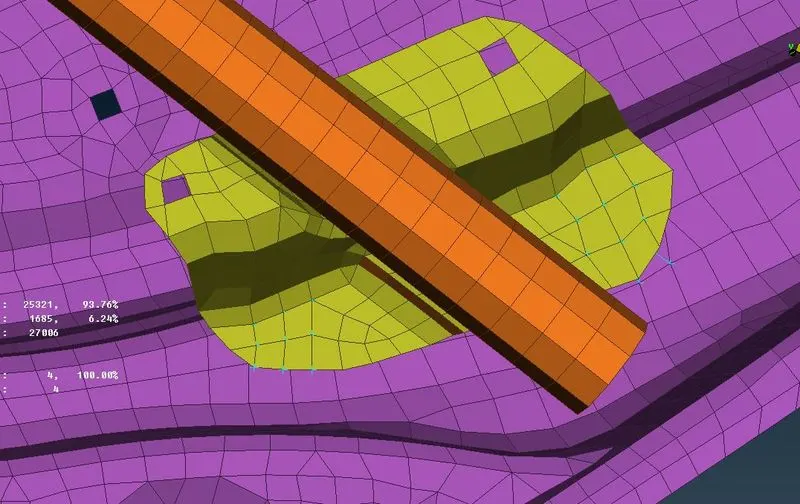
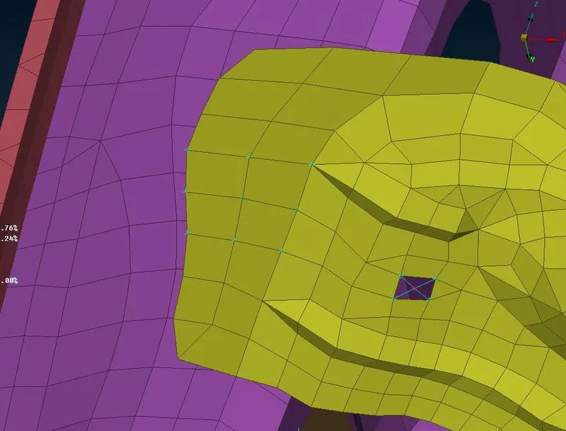
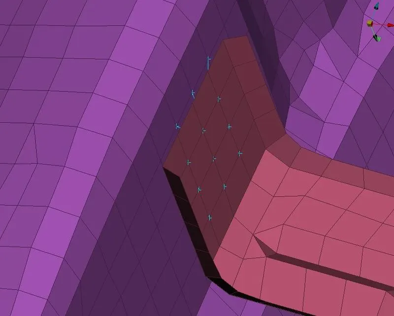
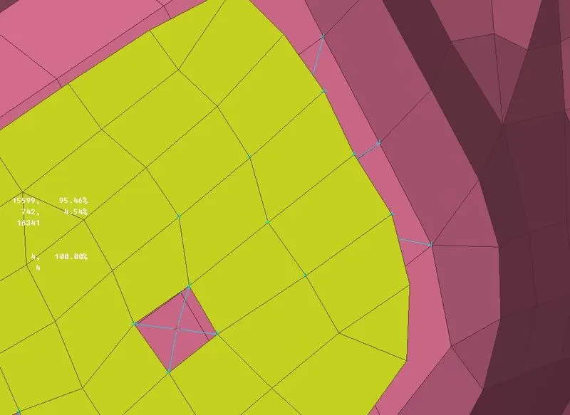
The other RBE2 cluster elements on the model are formed by selecting the many nodes and on the confirmation, a single master node is formed for two different holes. the cluster and bolt RBE2 connections are shown in the figure.
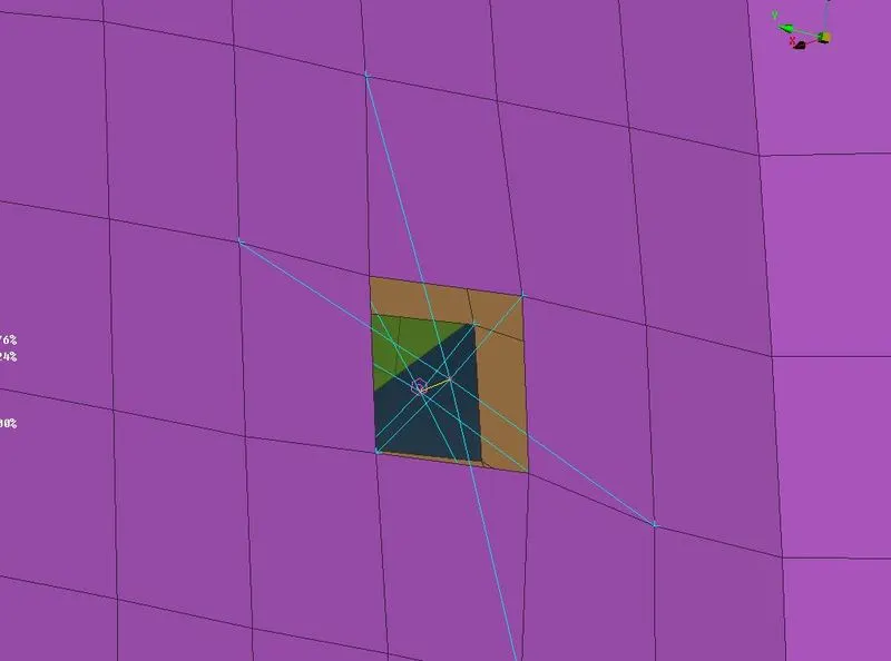
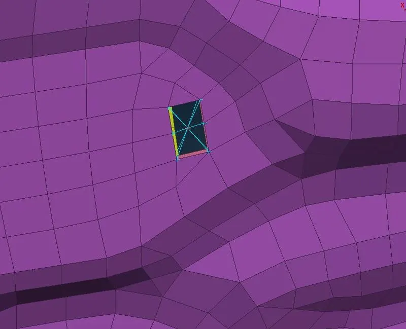
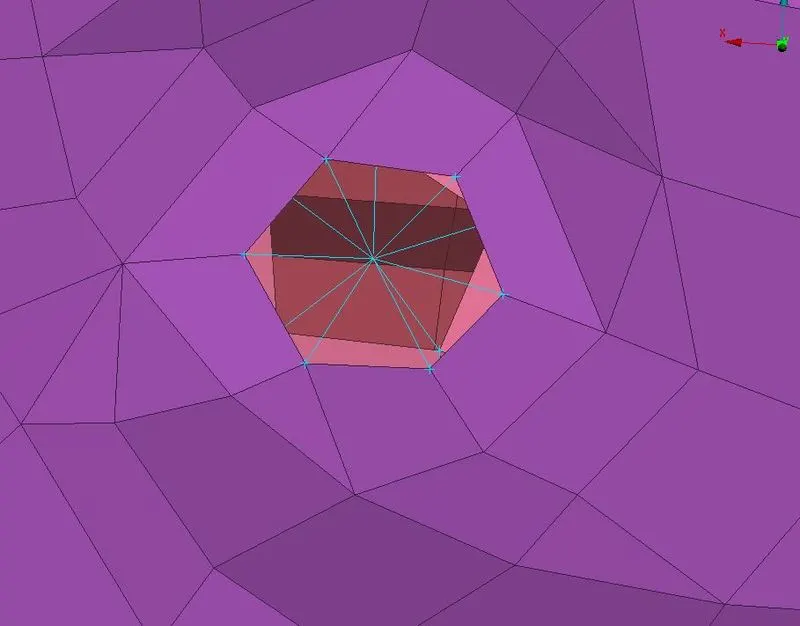
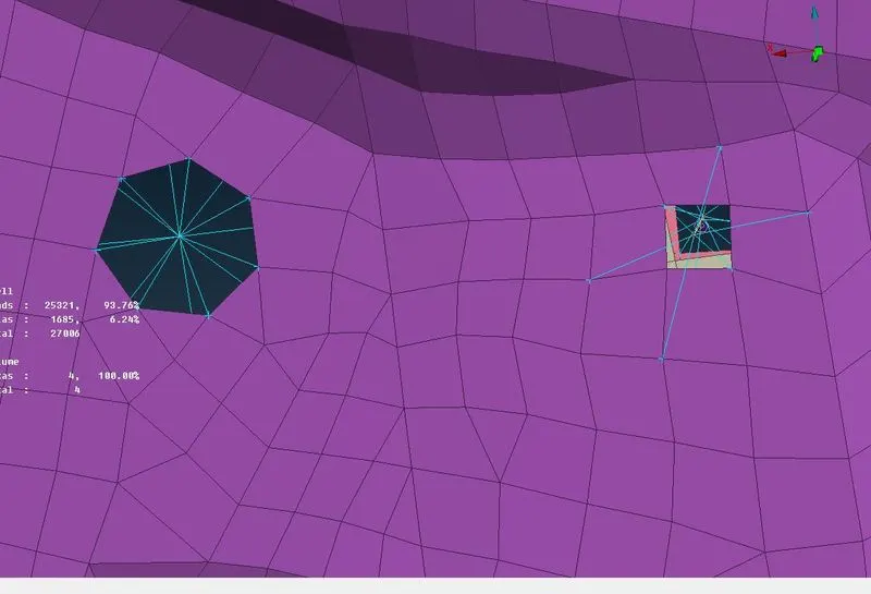
Before moving into the glass connection, the rail inside the door panel which helps the glass to move in and out has to be extended. once the rail is extended, the mesh has to be reconstructed on the extended surface. then the RBE2 connection is made between the rail and glass shown in the figure.
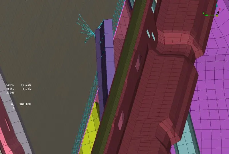
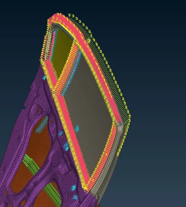
Moving onto the door glass, the bush connection has to represented between the weatherstrips and the door glass. CBUSH element is the spring element that has a damping co-efficient or stiffness values in all three different directions. Instead of providing three different elastic elements in three different directions, it is preferred to use one CBUSH elements. To establish the connection, the outside line of the door element is converted into a curve by using the feat2curve option. Then these curves are converted into spot lines. By selecting these spot lines in the connection manager, the bush connection between the glass and weatherstrip can be established. To establish the bush connection, the two-part has to be specified, the spot line on the door glass and the outer part of the inner panel is selected and the FE representation type RBE3-CBUSH-RBE3 is chosen. Since the distance between each part is long, the search distance can be increased until it establishes the connection. In the interface option, it is important to select the option called to keep all branches to establish the connection in all three directions and the bush Id should be created where the six stiffness values have to be provided. On realising the bush connection is established.
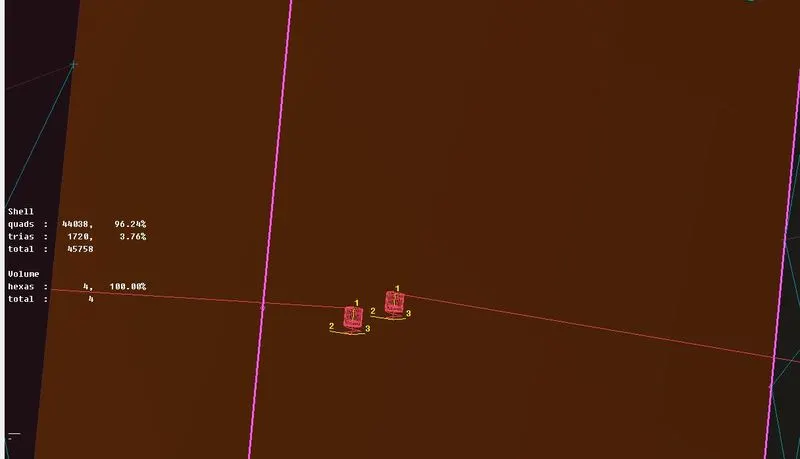
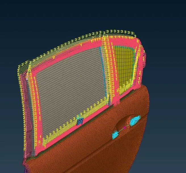
The same bush connection has to be represented on the other of the door. To establish, a spotline is transformed to a particular distance and the connection is made by selecting this spotline in the connection manager. The above procedure is carried out to establish the bush connections.
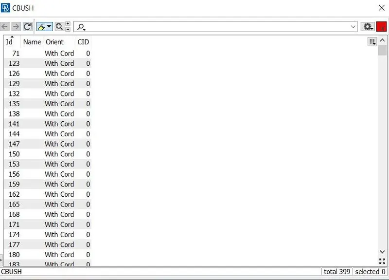
Once the bush connection is established, it is clear that the bush coordinates are different from the local coordinates and it important to make the bush coordinates in the direction of the local coordinate system. To align the bush coordinates to the local coordinate, the orientation of the bush has to be changed from vector direction to the cord direction and CID has to be provided as 0 and shown in the figure.
The check arm part has to be given a proper RBE2 element connection. check arm part helps the door to widely connected a rod to the door end. RBE2 connection for the check arm part is shown in the figure.
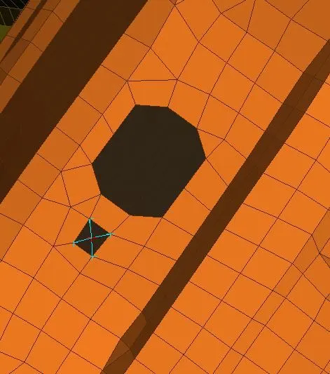
All the necessary connections are provided. The connections are very important, if proper connections are not established, the stress and frequency for any load will vary causing any model to fail while simulating the results.
Learning Outcomes:
I learnt how to establish the connections on the model and why it is important. I learnt how to establish a connection between rigid bodies and washer elements. I learnt how to establish the connection by using many nodes and a two-node option in RBE2 elements. I learnt how to establish the cluster connection. I learnt the difference between RBE2 and RBE3 elements. I learnt to establish the connection for seam weld and spot. I learnt how to establish CBUSH and Mass connections. I Learnt the different FE representation type for Spot weld, Bolt & nut, CBUSH, SEAM WELD for the parts which are parallel and perpendicular to each other. More I work, I get familiar with more different options NVH deck module.
Conclusion:
After completing this specific task, I would like to conclude that I get confident that I will establish the connection for any spotweld, Seamweld, CBUSH, bolt & nut, mass and any other rigid connections. I conclude that it’s great learning.