Week - 4 - 2D meshing for Plastic components
AIM:
This project aims to mesh the plastic component (Bottlecap) with varying thickness with a good flow of elements and to match the given quality criteria and mesh parameters. To mesh the Bottle cap, the mid-surface has to be taken for the given varying components and the mid surface has to be extended to the nearby surfaces.
Procedure:
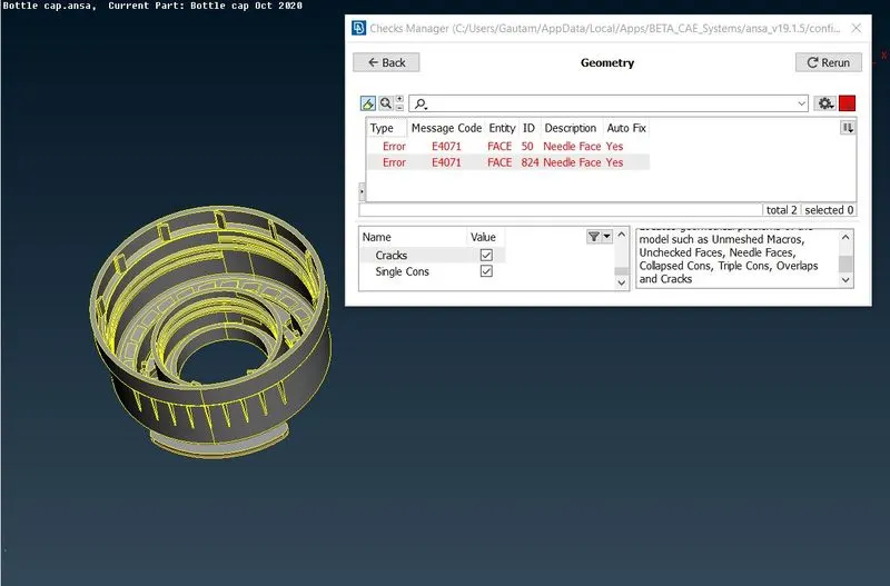
Once the model is imported in Ansa, the model is subjected to various check to clean up the geometry. Under geometry check, 2 single con errors have been popped up and the errors are cleared by using the auto-fix option. since the geometry topo is cleaned up, the material has to be defined in the material card. Orientation is done to get the same grey colour all over the surface. The single con error is shown in the figure.
.
As it has been clear from the property card, the bottle cap has a single property all over the surface. Since it is a plastic component the mid-surface has to be taken for all varying thickness segments to proceed further with the meshing. To take a manual mid-surface, the thickness has been measured at different segments. The outer cylinder and the inner cylinder have a thickness of 1.224 and 1.019 mm respectively. The mid-surface for these two cylinders is taken by using the offset command and half the thickness value is given in the opposite direction to extract the mid-surface.
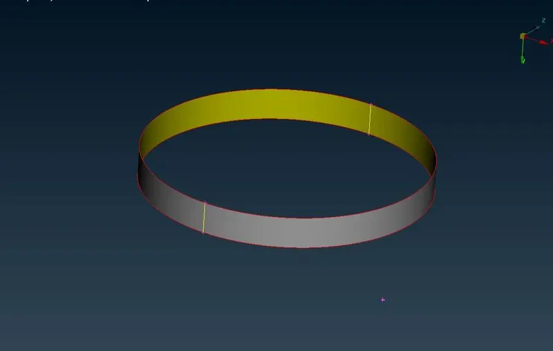
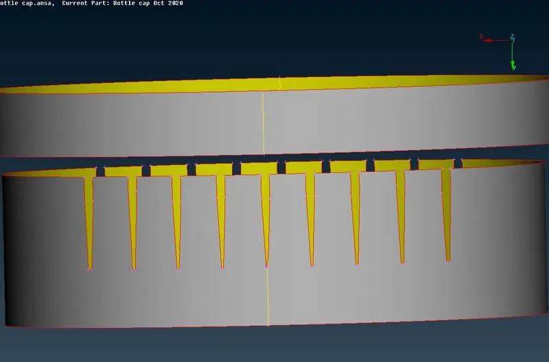
The gap in the inner cylinder is filled by using the new command. Since the fillet between the inner and outer cylinder has a different face on the inner and outer side, the gap between these two cylinders is filled according to the outer face by using the new command and the new surface is generated by selecting the cons of the outer and inner cylinder respectively.
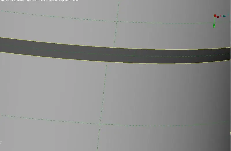
The two sets of 9 ribs are embedded on the opposite facet of the inner cylinder and the fillet area. Each nine ribs have a varying thickness such as 0.369, 0.2666, 0.216, 0.186, 0.178, 0.186, 0.216, 0.266, 0.369 respectively. Since the ribs have two different cross-sections, the mid-surface is extracted by using the middle command and the extracted mid surface is extended to the inner cylinder by using the Extend command. If the mid-surface is extended outside the inner cylinder the intersect command is used to separate the faces and the unwanted extended surfaces can be deleted. When the surface is extended to mid-surface, the triple cons are generated since the con shares between more than two surfaces.
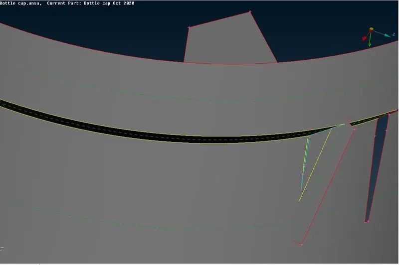
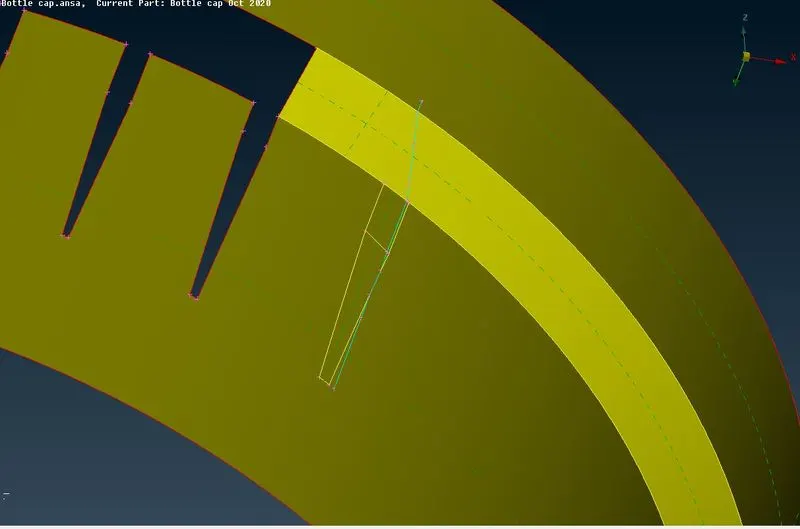
The thread and teeth are attached to the inner surface of the inner cylinder. To Extract the mid-surface for the thread, a curve is generated in the centre between the two cons by using the Middle command in the curves tool. Then the generated curve is projected to the middle surface of the inner cylinder by using the project command in the cons tool. The new surface is created by selecting the curve and the projected curve on the mid-surface of the inner cylinder by using the new command and the mid-surface is generated for the thread. Since the thread is extended to the mid-surface of the inner cylinder it forms a triple con.
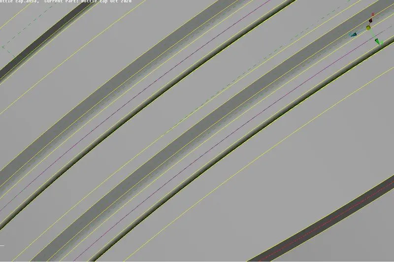
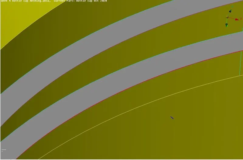
Since the teeth have a different thickness all over its body, generating a mid-surface in one go is not possible. On the outer surface, the curve is generated in the middle and the con on the surface is projected towards the mid-surface. Then, the mid-surface is generated by creating the new surface between the generated middle curve and projected con on the base mid-surface. The same process is carried out for all other teeth to extract the mid-surface.
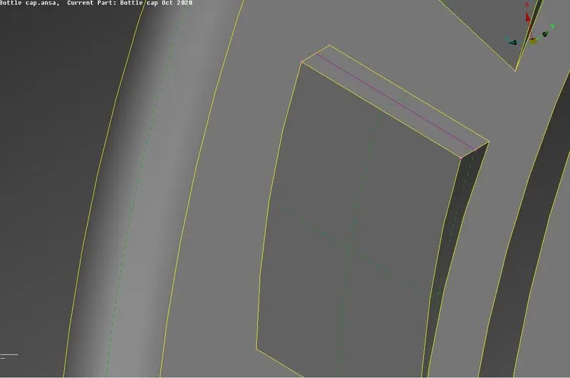
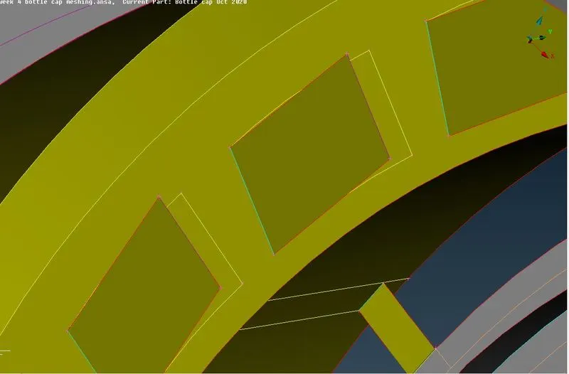
A total of 12 curved like features are attached to the inner surface of the outside cylinder and fillet respectively. Each feature has a different cross-section and to extract the middle surface, the Middle command in the face tool is used. The Mid-surface is generated by selecting the two opposite faces. The extracted mid-surface is then extended to the mid-surface of the outer cylinder. If the mid-surface is extended outside the outer cylinder the intersect command is used to separate the faces and the unwanted extended surfaces can be deleted. When the surface is extended to mid-surface, the triple cons are generated since the con shares between more than two surfaces.
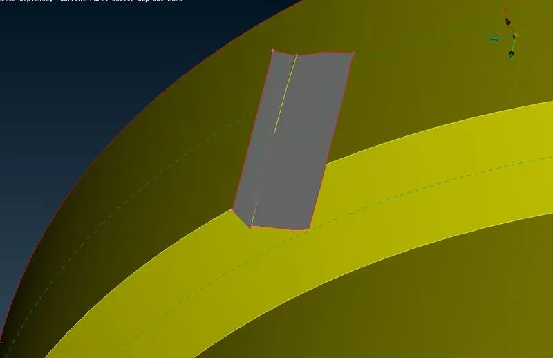
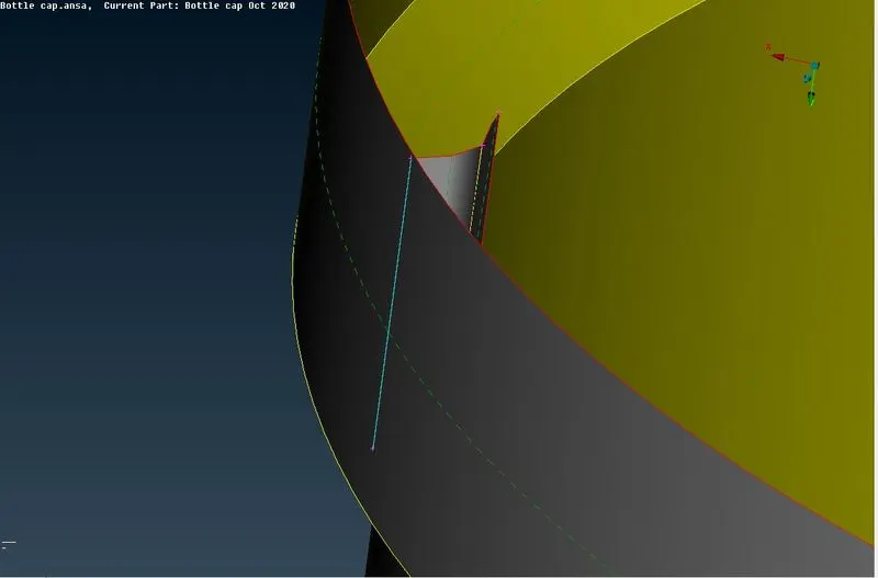
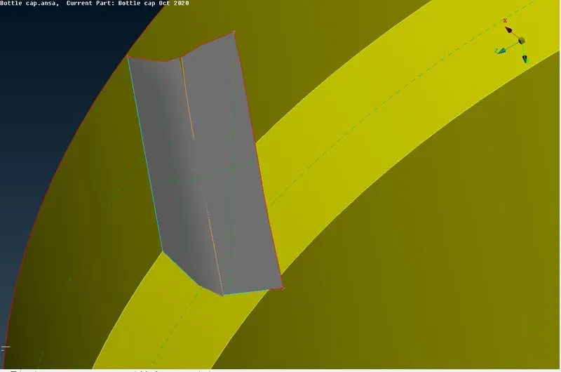
The same procedure is repeated to generate the mid-surface for the other features present inside the bottle cap such as other cylinders and threads. The mid-surface of the cylinder inside is then extended to the bottom mid-surface of the bottle cap forming a triple con. The Mid-surface of the thread inside the bottle cap is then extended to the respective mid-surface to get a closed system and connectivity everywhere.
To generate the mid-surface on the bottom part of the bottle cap, the thickness has been measured by selecting the cons. The thickness measured is 1.530mm. The middle surface for the bottom part is generated by using the offset command and half the thickness value is given in the opposite direction since the surface is in grey colour.
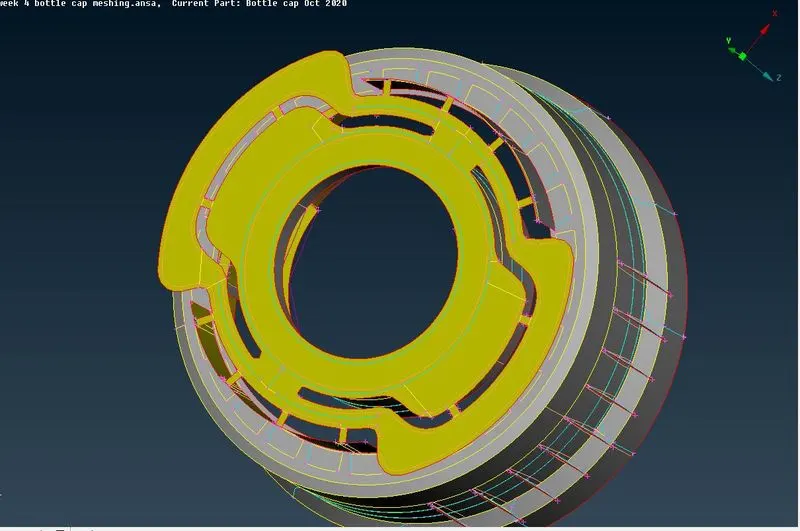
The connectors in the base part of the bottle cap measure 1.530 and 1.617 mm and the mid-surface is generated by using the Offset command. The Generated mid-surface is then extended to the nearby mid-surface to form the closed system and it forms double cons and triple con according to the sharing surfaces.
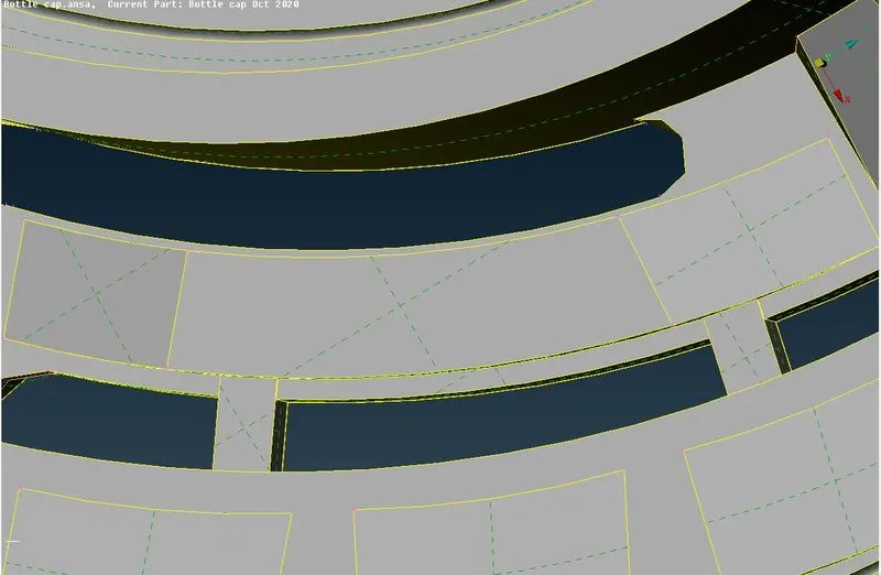
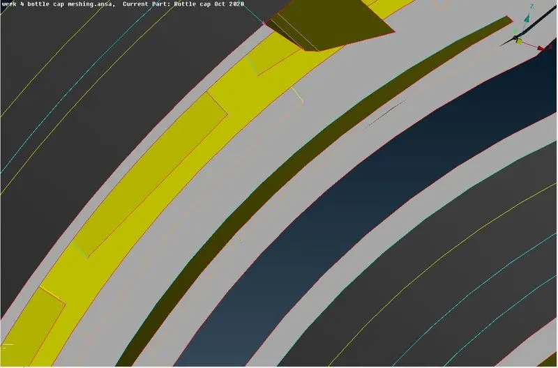
If the feature has a non-uniform thickness across the cross-section, the Middle command is used to generate the mid-surface by selecting the opposite faces. The mid-surface for the feature shown in the below figure is extracted in such a way and extended to the respective mid-surface to produce the connectivity.
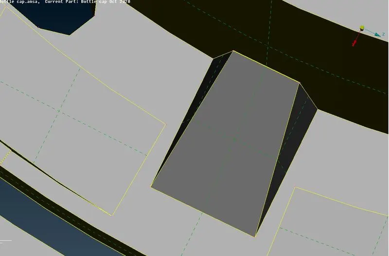
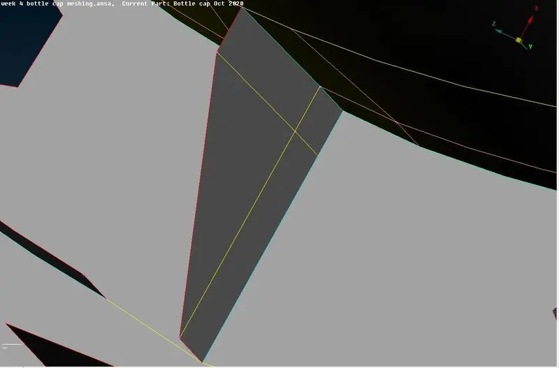
For the following feature shown in the below figure, the mid surface is extracted from the vertical side to form connections between the previously generated mid-surface. The mid-surface for this feature is extracted by measuring the thickness and by using the offset command. Once the mid-surface for every component is done and extended, the model is now ready for meshing.
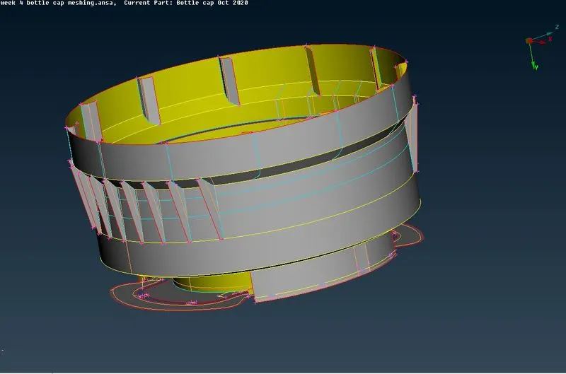
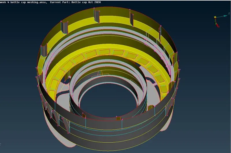
The mid-surface for the whole bottle cap after extension to the nearby mi-surface is shown in the figure.
Before going to the mesh module, the mesh parameters and quality criteria have to be set up as per the given conditions. Once the conditions have been set up, the mesh can be generated in the mesh module. Before meshing, the perimeter and macros edges should have the given element of 1. The distance between the nodes has to be checked at critical surfaces to avoid quality failures. If the distance between the nodes falls below the minimum length the defeaturing of the surface should be done. when the mesh is generated and it falls for minimum length by using the edge2perimeter option, the new con is generated from the formed elements and joining the cons helps to avoid the quality failure at the critical points like fillets and curvy areas. The mesh parameters and the quality criteria are given in the following images.
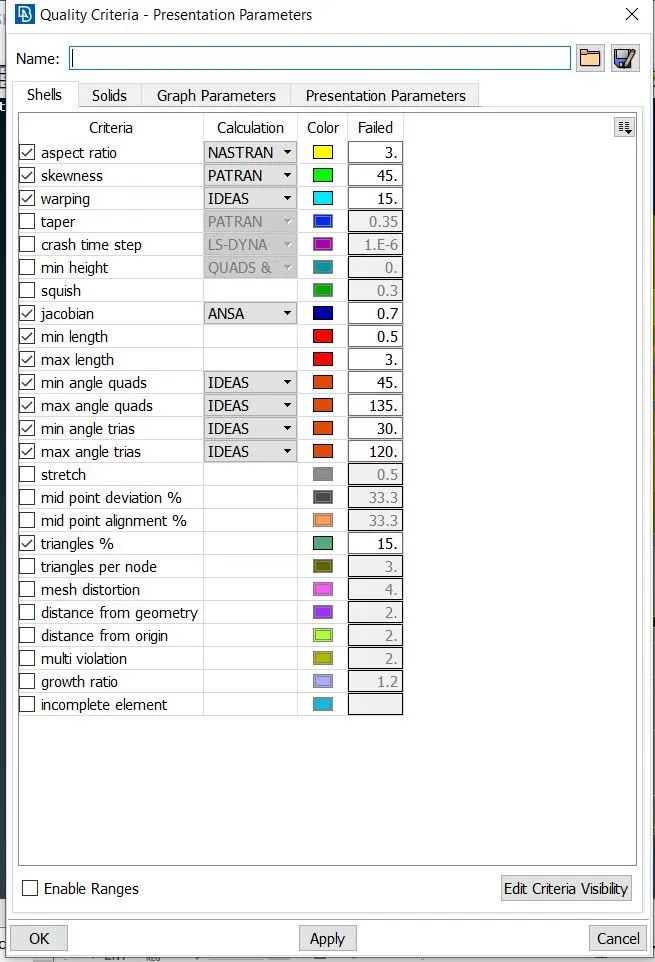
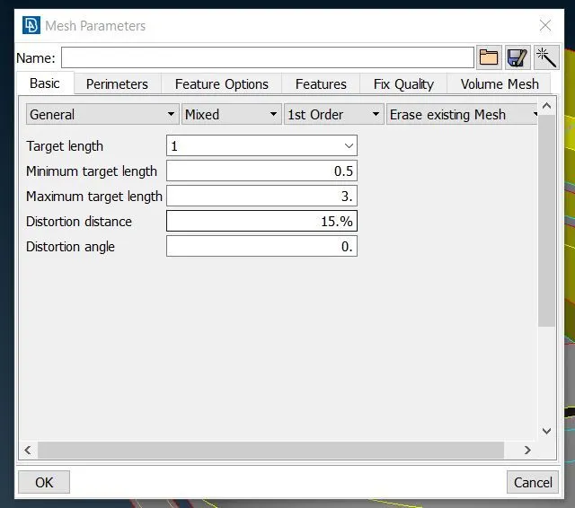
The mesh is generated by using the Best mesh option. To obtain quality elements and good mesh flow, the different cuts are introduced in the mid-surface. From the figures, it is clearly understood that parts with manual cut have a good element quality and good mesh flow. After the generation of mesh, reconstructing it helps to get a greater quality element. The opposite trias and trias at the perimeter should be eliminated by using split, reconstruct and smooth option. As soon as the mesh has been generated, shadow mode should be shifted to hidden mode. In hidden mode the falling elements are visible for different qualities and care should be taken to avoid the off elements. All the off elements on the different parts should be cleared and each part should have good mesh flow and patterns.
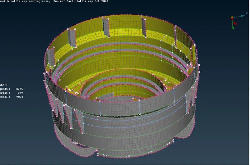
The off elements next to the triple con are couldn’t be cleared since it has a smaller area and failing for the minimum distance and other parameters.
Learning Outcomes:
I learnt how to clean up the geometry in the topo module, how to take the mid-surface for different parts for varying thickness by using different commands such as offset, middle. I learnt how to take the middle surface for teeth and thread by generating the curves in the middle of the surface. To form connectivity between the generated mid-surface, I learnt how to extend the surface to the nearby surfaces. I learnt how to intersect the two faces and to do delete the unwanted extended surfaces. I learnt to create a new surface between the two existing surfaces by using the new command and by selecting the cons. I learnt to set up the mesh and quality parameters, how to deal with the critical surfaces such as defeaturing, and how to achieve good mesh flow by giving manual cuts and I learnt how to deal with the generated trias. The more I work, I get familiar with more different options in the topo and mesh module.
Conclusion:
After completing this specific task, I would like to conclude that I get confident that I will generate the mid-surface for any component with varying thickness and I will achieve a good mesh flow and quality on any parts. It is very difficult to clear the mesh quality parameters near the triple cons generated on the surface where it had a minimum distance to generate the mesh. I conclude that it’s great learning.