Week 6 - Creating connection for Rear door
Objective:
To create suitable connections in rear door FE model provided with pre processing.
Step 1:
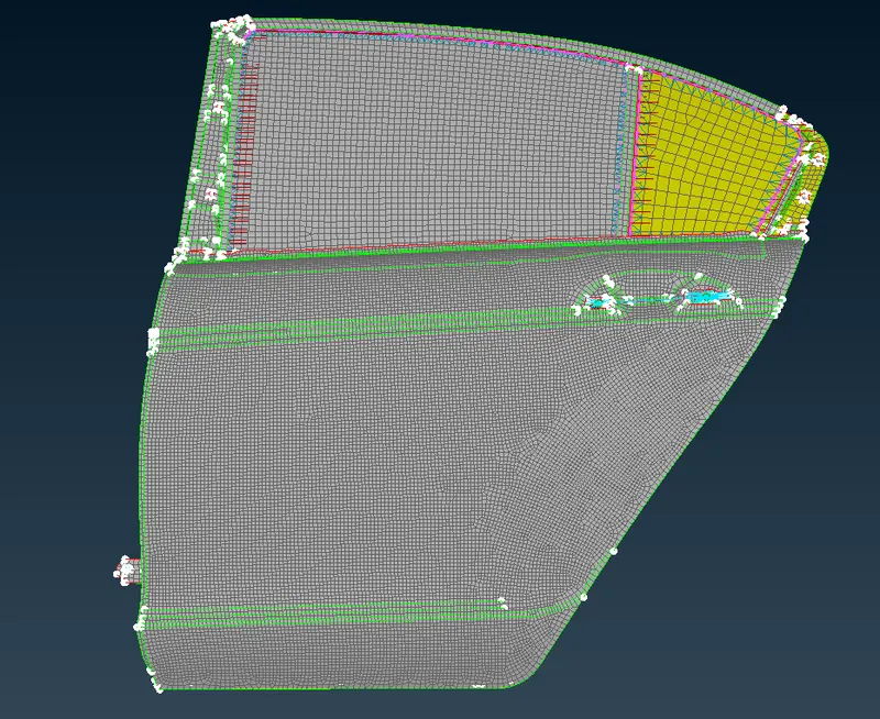
Import the FE model from source. Following is the FE model provided. It contains single PID which can be used for assigning connections.
Step 2:
To Start the assignment of connection we can start from door hinge part. 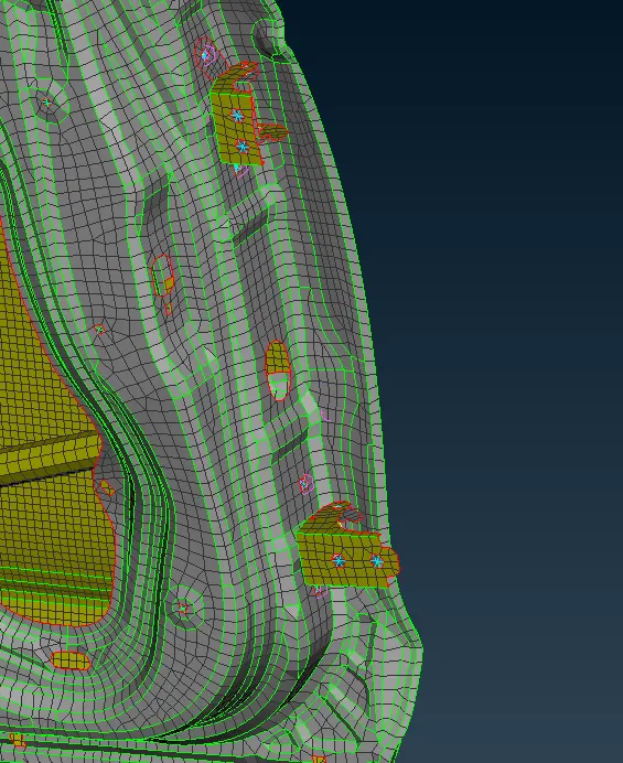
Here we have to assign the bolt connection using Elements>RBE2 in NASTRAN Domain. First we need to make COG points at every holes for bolts, then go to Convert>3d points>Connection type>Bolt.
Then go to connections tab and select the created bolt point & assign TID to bolt. Provide required values and select realize.
In the set options the sections P1,P2 & P3 needs to be assigned as there are three layers. Right click on P1 a dialogue box appears go to modify & press F1 it will let you select the part required.
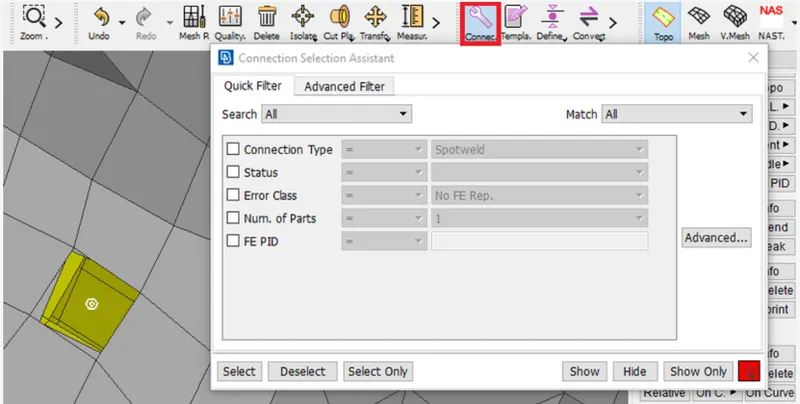
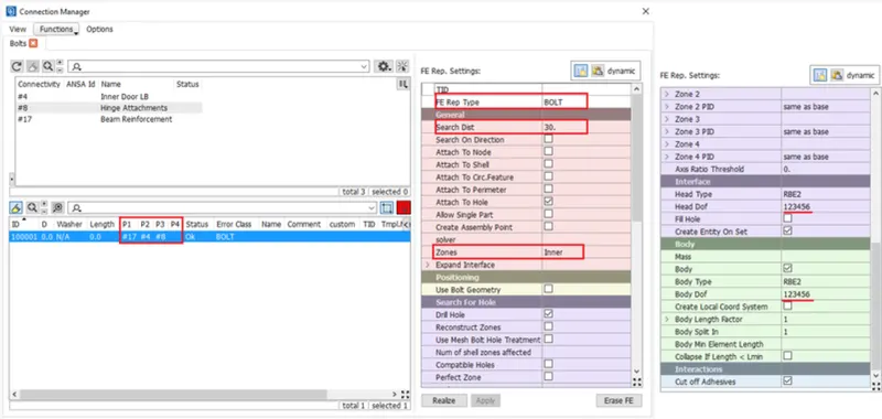
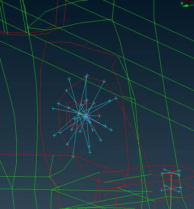
The RBE 2 Bolt representation will be shown. Do it for both hinges.
Now provide same connection for Rotating part with Degree of Freedom to contraint from all direction excepth rotational Z Axis. Keeping CM=12345. This allow the door to open in necessary direction.
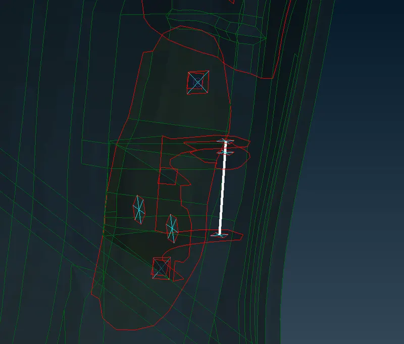
Step 3 :
To assign door handle reperesentation we have to assign weight of door handle. To do so we have to assign RBE2 Connection using Elements>RBE2>Manynodes. After creating RBE2 connections saperately Use Elements>RBE2>Two nodes and at the centre node mass will be concetrated by using Elements>CONMi>CONM2>Nodes. Here assign the mass M in tonnes.
Step 4:
Connection of Window glass will be assigned as a fixed connection. Here we will use CBUSH RBE3 element, where there is window weather strips are present.
First use the outer edges of glass to form the curves. Using Perimeter>Feat2Curve tool. After creating curve take offset of that curve in y-direction at 5mm. Now convert those curves one by one to Spot lines Using Convert>Curves tool. Don't group during this action.
After converting these curves use connection manager to create these CBUSH connections. For the options we need to select the P1, P2 and P3. Use Spacing (S) to be 10 mm. The FE Rep type will be RBE3-CBUSH-RBE3. Enter the search distance 20 and Keep all branches checked, create a Bush ID. In PBUSH ID box, press Shift+? to create new PBush ID. Enter 6 Stiffness values required. Then Apply and Realize the connection.
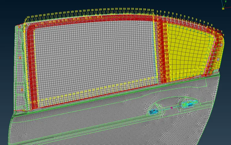
After Realization of the connection we will reorient the spot line with local coordinate system. Go to Database>Elements>CBUSH. All the CBUSH elements will be displayed. Select all and Right click>Modify. In modify dialogue box go to orient>Cord press + sign. Then Opened dialogue box shows CID, Enter 0 as value and press enter. The Spot line connections will assigned with local coordinate system.
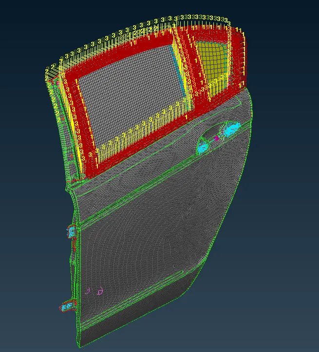
Final Model :
Learning Outcome:
1. Learned about various connections availble in the NASTRAN Deck.
2. Learned to convert points and curves into connection points/Lines.
3. Learned to assign properties to connections and edit said connections as per requirements.
4. Learned about the concept of weather strip & its importance, Along with concept of tailor welds.
Conclusion :
Suitable connections were deployed between various components in the rear door model.