Week 6:- Clamp Unit & Pin-Clamp Unit Design Challenge
OBJECTIVE :
- To design 3 Different types of Swivel Clamp Unit with Different Riser, Blade, and Clamp Arm for the given Car Panel using 3-2-1 principle.
- To design a Pin-Clamp Unit for the given Car Panel.
3-2-1 principle
- The 3-2-1 method is a work-holding principle where three pins are located on the 1st principle plane, i.e., either XY, YZ, ZX. And two pins are located on the 2nd plane perpendicular to the 1st plane, and at last, one pin on the plane is mutually perpendicular to the 1st and 2nd planes.
- It represents the minimum requirement for the locating elements.
- The locators along with the clams which hold the part in place, provides equilibrium for all the forces.
- Stability is satisfactory if all three rest buttons are widely spaced and resultand cutting force lies within the triangular area between the buttons.
- If resultant cutting force lies outside the triangular area then it generates a moment which in turn lifts are overturns the component.
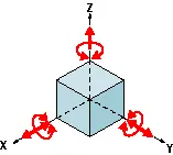
Locating Process in 3-2-1 method
We have two objectives when mounting a part in a fixture for machining
1. Accurately position the part at the desired coordinates.
2. Restrict all six degrees of freedom so that the part cannot move.
A widely used method of accomplishing these two objectives uses the 3-2-1 principle, so-called because it entails three steps that employ three, then two, then one fixed points of known location. Since that adds up to six fixed points, it’s also known as the six point method.
In the three steps of the 3-2-1 method, three mutually perpendicular planes, called datum planes, are introduced, one at each step. These three planes define the workpiece position, and together with opposing clamping forces fully constrain the part. Let’s take a look at the details of the 3-2-1 method
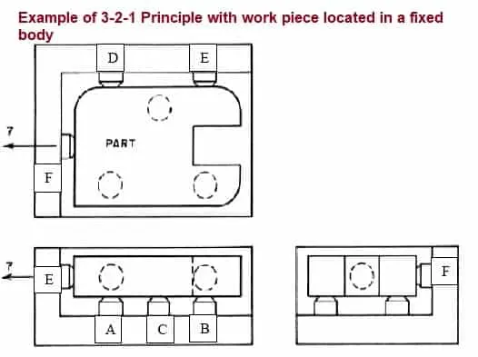
First Plane
Geometry tells us that three points are required to define a plane. This is the "3" in 3-2-1. So, three specific points are used to define the first plane. Fewer than three points cannot define a plane, and in the real world dimensional tolerances mean that four or more points will not be coplanar.
A real-world, less than ideally perfect part placed on four or more reference points will, in fact, rest on only three of the points due to its less than perfect surface. Different parts may rest on different combinations of three points, resulting in variation between finished parts. A stool can be used to illustrate this concept.
A two-legged stool would certainly be unstable. A three-legged stool sits rock-solid. A four-legged stool is often found to rock. In the illustration, a three dimensional part, represented by a cube, is placed on a datum plane defined by three support points.
The part’s six degrees of freedom have now been reduced to three. It can still move along the X or Y axes, and it can still be rotated about the Z axis. The part cannot move along the Z axis because it is held against the plane by clamping force.
Second Plane
A second plane, if it is perpendicular to the first, can be defined by two points, the "2" in 3-2-1.
The part is now constrained to one degree of freedom ,movement along the Y axis.
The part cannot move along the X or Z axes because it is held against the planes by clamping force.
Third Plane
A third plane, if it is perpendicular to both of the first two planes, can be defined by one point, the "1" in 3-2-1. The part is now entirely constrained. It cannot move along or rotate about the X, Y, or Z axes. (Remember that the part is held against each of the three planes by clamping force.
Supporting
- The part is supported from "below" with reference to the Z axis. (Introduction of the first reference plane.)
- Gravity positions the part against the support locator.
- Provide adjustable auxiliary support points as needed to prevent deflection.
- Vertical location with respect to the fixture is now established
- The part is positioned horizontally, in the X-Y plane. (Introduction of the second and third reference planes.)
Holding
- The part is clamped against fixed locators. Therefore, a known and unvarying position of the part is maintained with respect to the X, Y, and Z axes.
- One strap clamp or clamp arm will restrict the workpiece in three dimensions due to friction between the workpiece and clamp. However, friction alone may not be enough to prevent the workpiece from moving during machining.
- Cutting forces will not move a properly supported and clamped part.
Summary of 3-2-1 principle
A workpiece will be completely confined when blanked against
- 3 points in one plane: The “3” in 3-2-1 refers to 3 locators (passive fixture elements) on the primary locating/datum surface.
- 2 points in another plane: The “2” in 3-2-1 refers to 2 locators on the secondary locating/datum surface.
- 1 point in a third plane: The “1” in 3-2-1 refers to 1 locator on the tertiary locating/datum surface.
Clamp Unit
A Clamp unit is a unit which is designed to clam or hold the car panel.
The various parts of a Clamp unit are as follows,
- Clamp Arm
- Clamp Cylinder
- Finger
- Rest
- Locators
- Shims
- Plate
- Riser
Clamp Arm
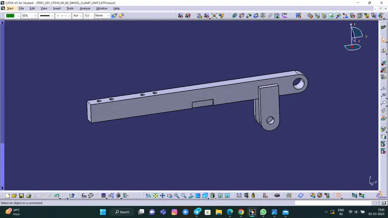
- A Clamp Arm is the part of a cylinderto which all the moving parts are fixed.
- It is a bought out part.
Swivel Cylinder
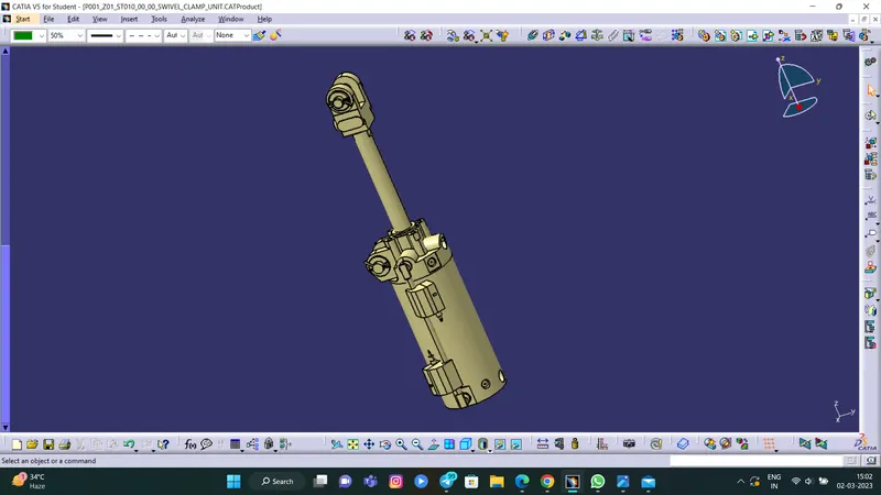
- Swivel cylinder is pneumatic device that works with pressurized air.
- The cylinder used here is Clevis cylinder.
- It has a bore size of 63 mm, width of 19.5 mm and a stroke of 100 mm.
- It is used to open and close the components attached with the clamp arm.
- It is a bought out part.
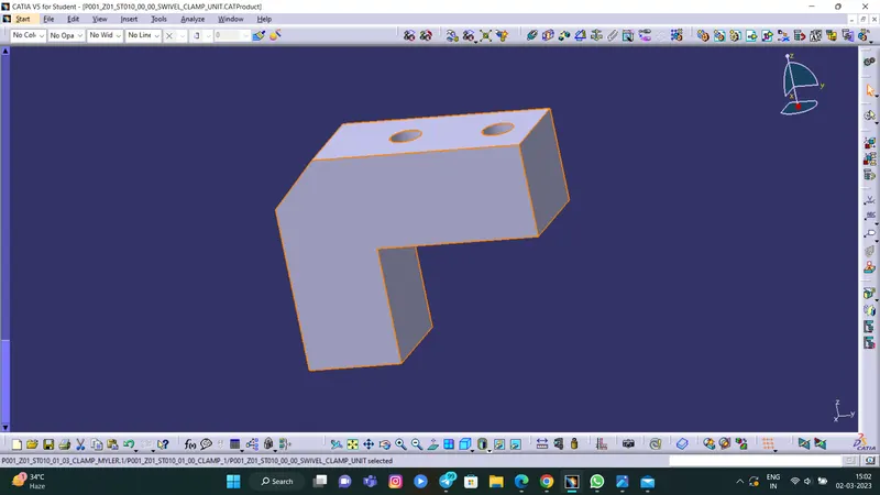
Finger
- Finger is an NC block which is attached to the clamp arm of the cylinder.
- It used used to hold the car panel by pressing it against the rest.
- It is also known as Clamp Mylar.
Rest
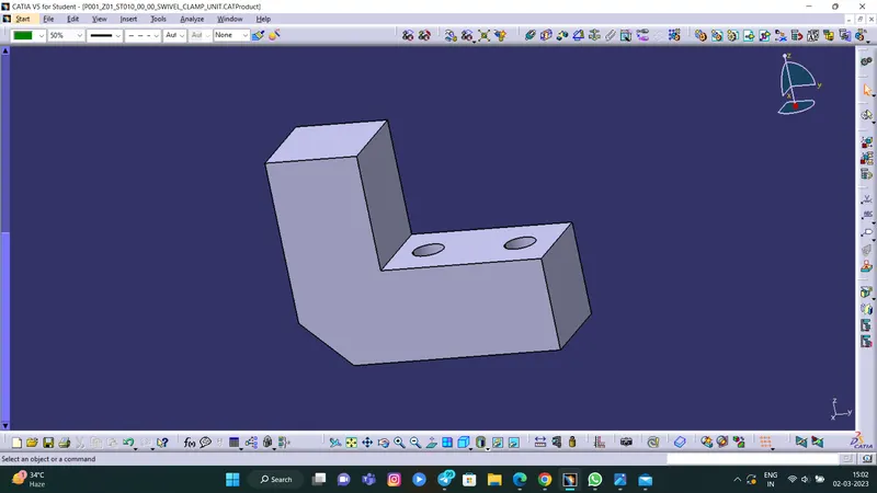
- The Rest is attahced to the car panel to provide support to it.
- It also resists the clamping force provided by the finger and clamp arm.
- It is also known as Rest Mylar.
Locators
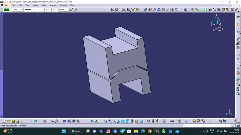
- Locators are employed here to support the clamp arm.
- It has a male and a female component.
Bush
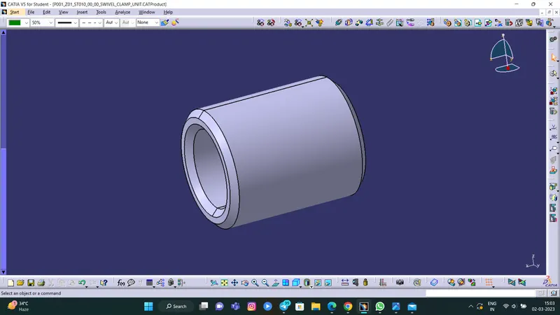
- Bush is used while inserting pins into holes.
Shims
- Shims are used foe the adjustment of the locators.
- In generaal these are standard parts.
- Shim blocks can be adjusted according to the manufacturing deviations.
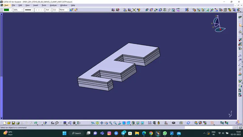
Plate
- Plate or Blade is an optional block which can be used according to the design requirements
- Blade is the part which is used to connect the entire unit with the riser block.
- It can either be a make part or a standard part.
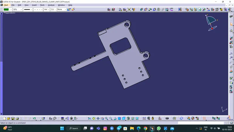
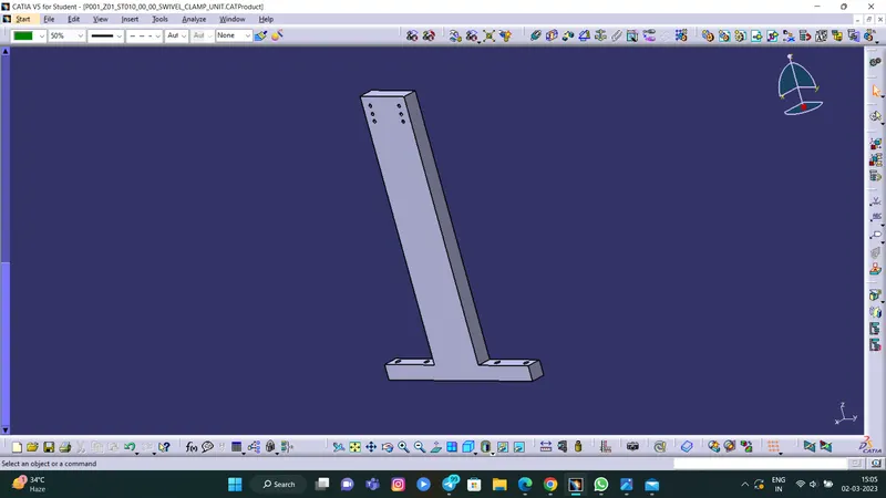
Riser
- Riser is the part on which the all the units are mounted.
- It provides support to the unit and attaches itself to the base.
- It can either be a make part or a standard part.
Pin-Clamp Unit
- Pin should have grinding surface on shaft with fits on to which the pin retainer will be fitted
- The mounting surface of the pin should be a fine machined surface.
- The pin should have a step machine surface to lock the rotation, which matches with the pin retainer
- The mounting surface of the pin retainer to the blocks should be a machined surface. A
- All machined planes should be perpendicular to the axis of the pin shaft.
- Pin must have a fastening provision like tapped hole from the bottom or a V grove from the side
- A pin must be hardened (Heat treatment) and black oxide finished in general.
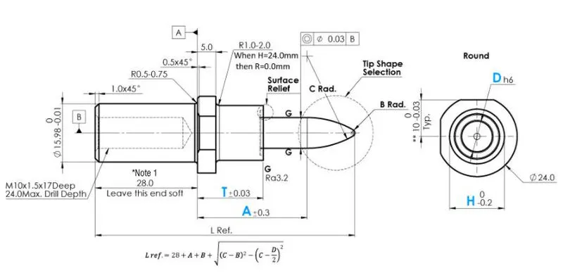
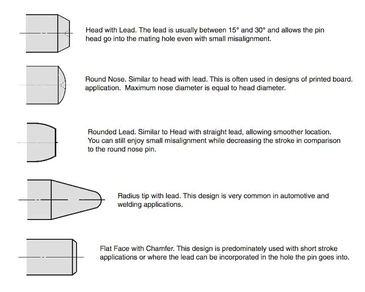
The two types of Pin units used were,
- Circular Pin
- Diamond Pin
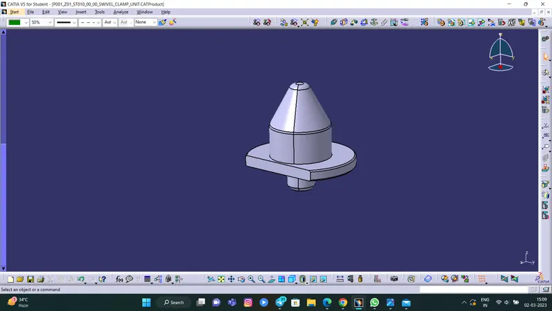
Pin Reatainer
Pin Reatainer is a part which holds the pin in place.
It restricts the rotation of the pin mounted on it.
It can either be a make part or a standard part.
- Pin reatainer must contain a hole in it in order to mount the pin.
- The surface on which the pin is mounted must be a machined surface.
- It must contain a step to lock the rotation of the pin.
- The surface which is mounted with the blocks must be machined.
- It can be fixed with the riser using a block.
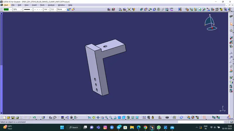
Shims
- Shims are used foe the adjustment of the locators.
- In generaal these are standard parts.
- Shim blocks can be adjusted according to the manufacturing deviations.
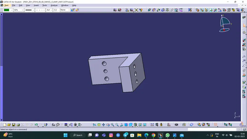
Block
- Blocks are generally used to accommodate the shimming directions.
- It is also used for the ease of design.
- Blocks can be of L shape.
Riser
- Riser is the part on which the all the units are mountIt provides support to the unit and attaches itself to the base.
- It can either be a make part or a standard part.
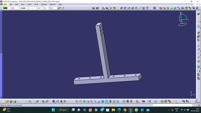
MODEL RESULTS :
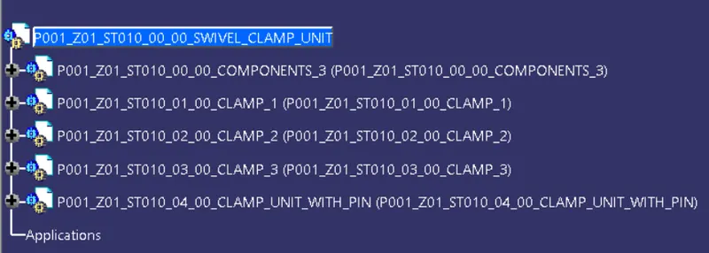
Feature Tree
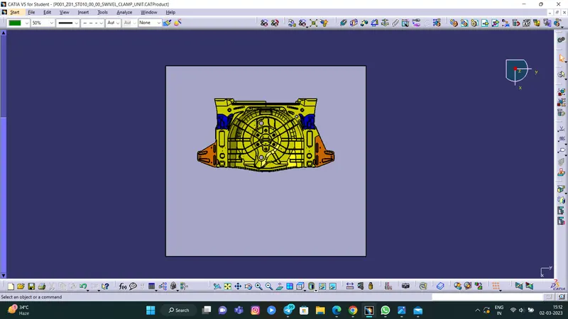
Car panel
Clamp Unit 1
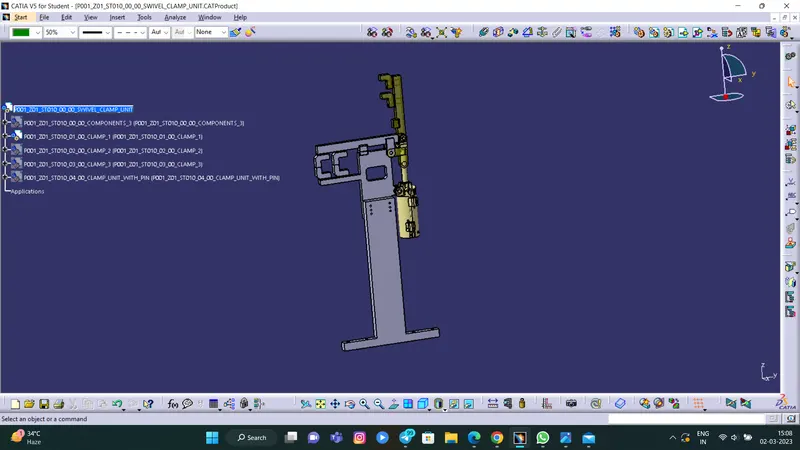
Clamp Unit 2
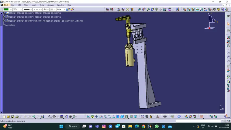
Clamp Unit 3
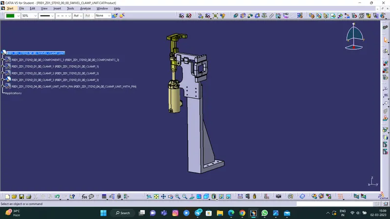
Pin-Clamp Unit
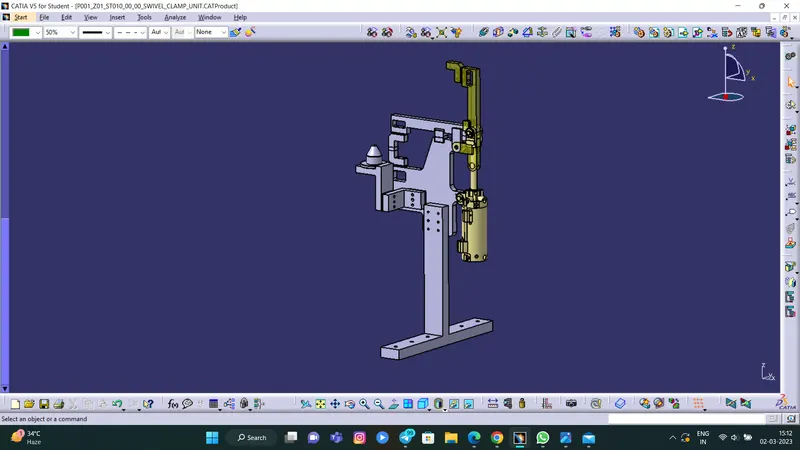
Clamp Units with Car panel
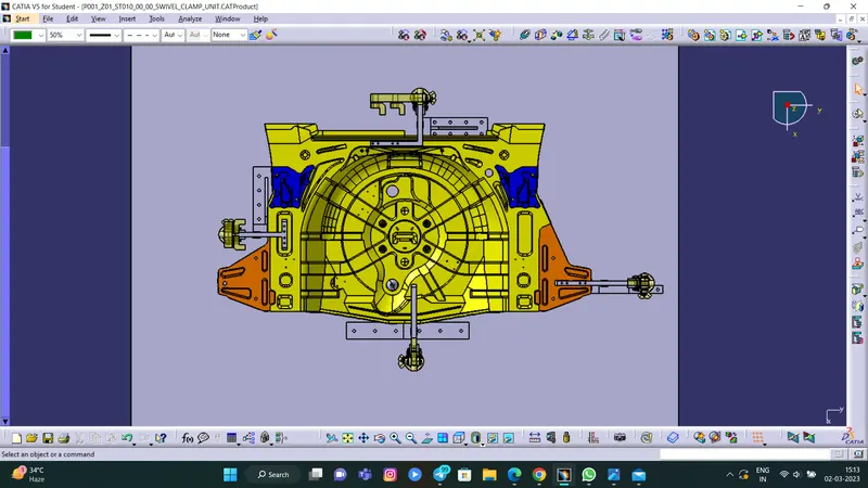
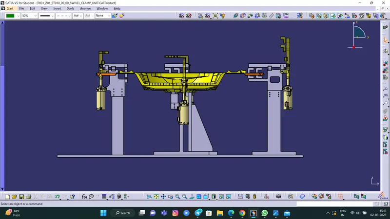
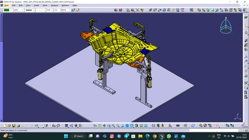
CONCLUSION :
- The Swivel Clamp unit was created with proper design methodologies.
- The Pin Clamp unit was created with proper design methodologies.
- Necessary images and part files were attached.