Week 6:- Clamp Unit & Pin-Clamp Unit Design Challenge
AIM:-
In this challenge we have to design 3 different types of swivel clamp unit with different risers,blade,and clamp arm for the given car panel and design a pin-clamp unit for given car panel with the optimum use of material and space constraints also considering panel thickness as 1mm for this unit.
3-2-1 Principle (achived by clamps):-
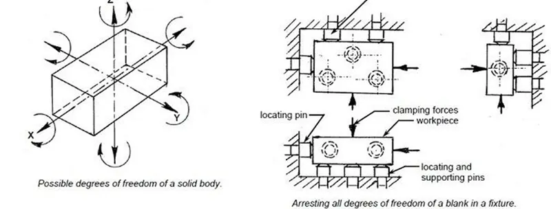
The 3-2-1 principle states that the six locators are sufficient to restrict the required degree of freedom of any workpiece. In this, motion is restricted using clamps and locators. A three-pin base can restrict five motions and six pins restrict nine motions.
The principle of location is being discussed here with the help of a most popular example which is available in any of the book covering jigs and fixtures. It is important that one should understand the problem first.
Any rectangular body many have three axis along x-axis, y-axis and z-axis. It can more along any of these axes or any of its movement can be released to these three axes. At the same time the body can also rotate about these axes too. So total degree of freedom of the body along which it can move is six. For processing the body it is required to restrain all the degree of freedom (DOF) by arranging suitable locating points and then clamping it in a fixed and required position. The basic principle used to locate the points is desirable below.
Factors Should be Considered While Designing a Clamp Unit:-
- There should be adequate space between the cylinder and another part like riser,car panel because cylinder moves or swing while opening and closing.
- Pin clamp unit is used where two panels or components are located for welding.
- Clamping make in such way that it clamps two car panels at ones
- All parts should snap and butt properly to each other.
- Avoid any clash.It will not arise issue at assembly.
Clamping Force:
Clamping force is the force required to hold a part against the locators. Clamping prevents the part from shifting or being pulled from the jig or fixture during the machining operation. The type and amount of clamping force needed to hold a part is usually determined by the tool working on the part and how the part is positioned in the tool. Sometimes the operation being performed is a factor, Clamping pressure, as a general rule, should Only be enough to hold the part against the locators. The locators should resist the bulk of the thrust. If a part must be clamped with a great deal of pressure the tool should be redesigned so that the tool thrust is directed at the locators and the tool body. Clamps must never be expected to hold all of the tool thrust.
- CLAMP CYLINDER:-
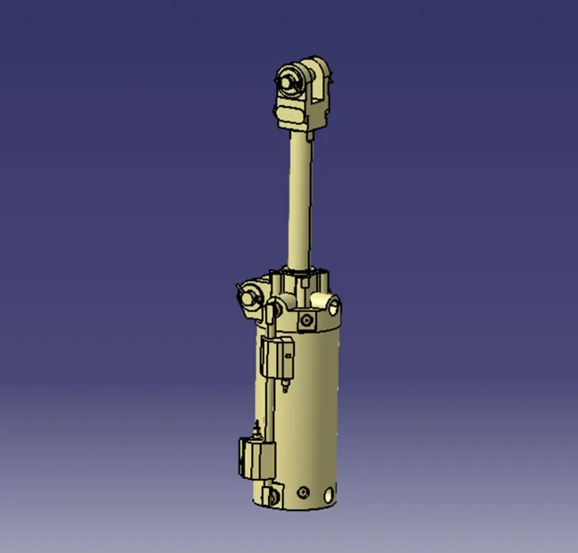
In this unit we used Clevis cylinder for clamping designated as CKG_1B_63_100Y
Nomenclature of cylinder as below:-
CKG1:-Series of cylinder.
B:-Clevis width as 19.5mm.
63:- Bore size.
100:-Stroke of cylinder.
Y:-End bracket i.e.double kunkle joint (M6 without tap)
- Clamp arm:-
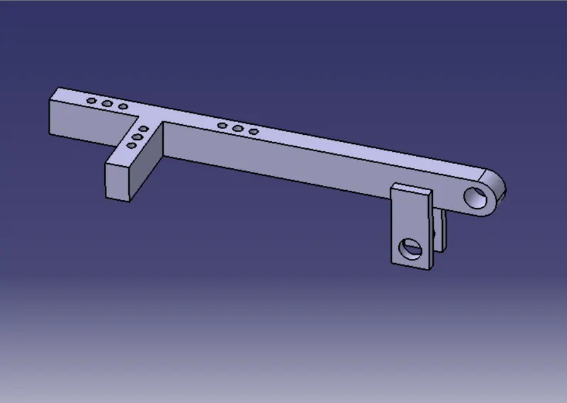
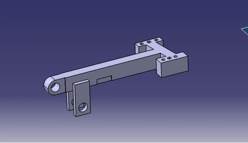
It is part to which clamp mylar mounted and also clamp cylinder is attached to the end of arm with the use of clevis pin.It has two plates of 8mm thickness welded and helps in rotating of clamp arm about pivoting point of blade.
The distance between cylinder rod hole and pivoting hole should be 50mm as shown in figure.This is necessary because cylinder stroke 100mm must be achivedd when it is at 90 degree position and clamp arm mounting hole must be in line with cylinder rod axis as shown in below figure.
Below figure shows 100mm stroke achived and clamp arm end in line with cylinder rod.see Y and z values.
- Mylar/NC Block/Fingers:-
These are parts are used to hold panel.They are globally called as mylar.Top side mylar are called as clamping mylar and bottom side mylar is called as resting mylar
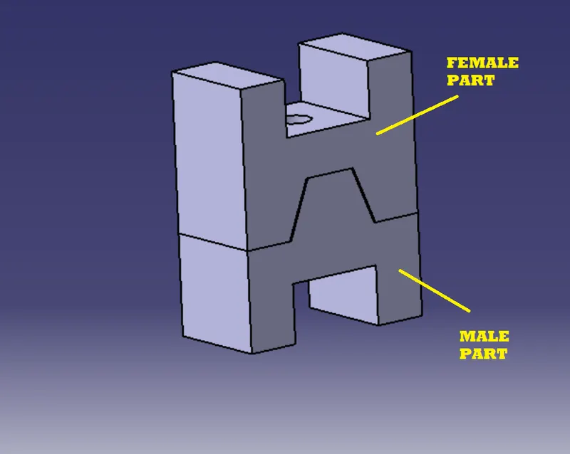
- Stopper:-
The function of stopper is to restrict motion of clamp arm.It avoids clamp arm to rotate beyond limits.it has two parts male and female.
- Blade:-
Blade is part to which all other units are attached for e.g. mylar,stopper,clamp cylinder,riser.blade is designed according to position of all other parts.
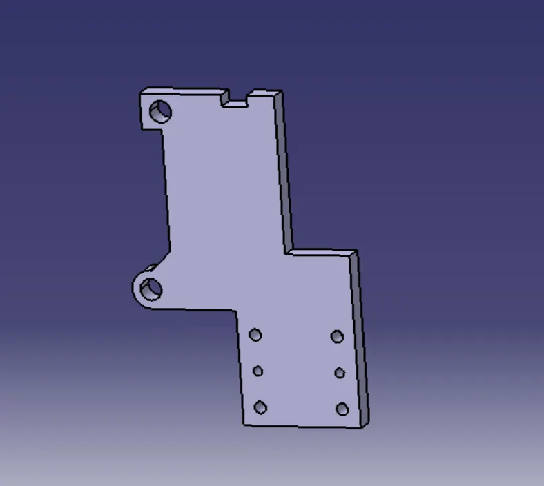
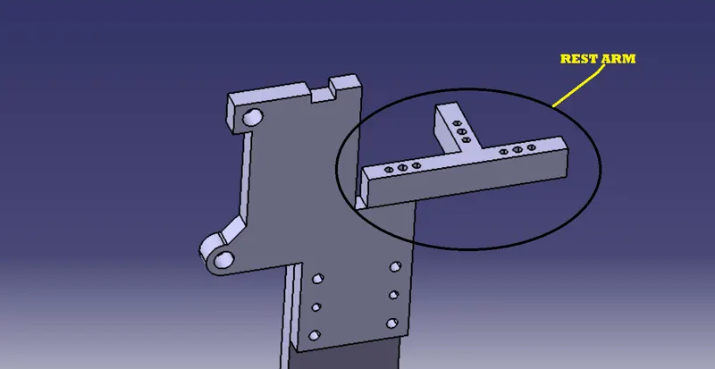
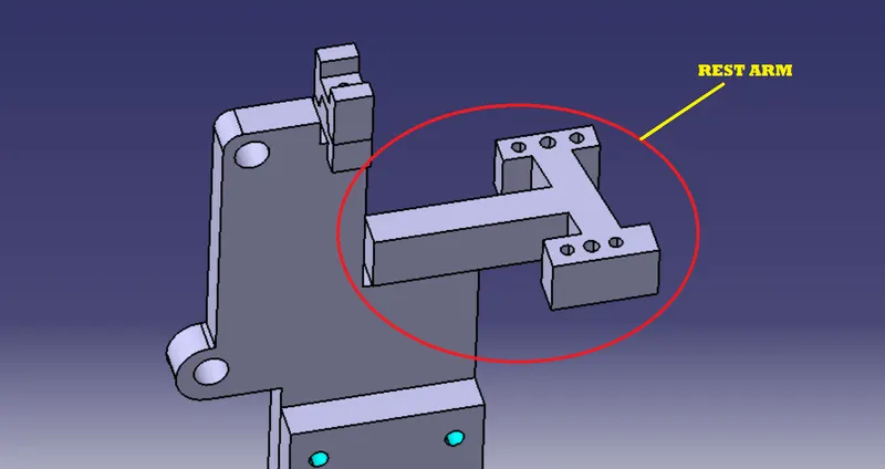
- rest arm:-
rest arm is mounted of th blade by weld to carry the rest mylars at botoom side of panel.
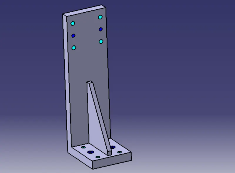
- Risers:-
Risers can be L-type,welded or square type or frame type,These are basically manufactured parts are used to give height to assembly.It is machined at mounted ends only to save cost.
- Shims:-
In fixture,we are providing tolerance to each part mostly manufactured.Those tolerance tends to stack up and reflect together.In order to avoid that we use shims so we can easily adjust after assembly so whatever stack up there will rectify it through shims.Shims come in thickness of 0.1,0.2,0.5mm etc.
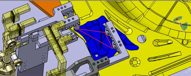
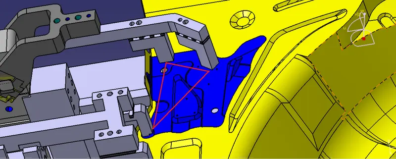
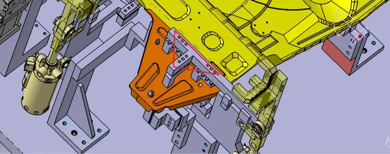
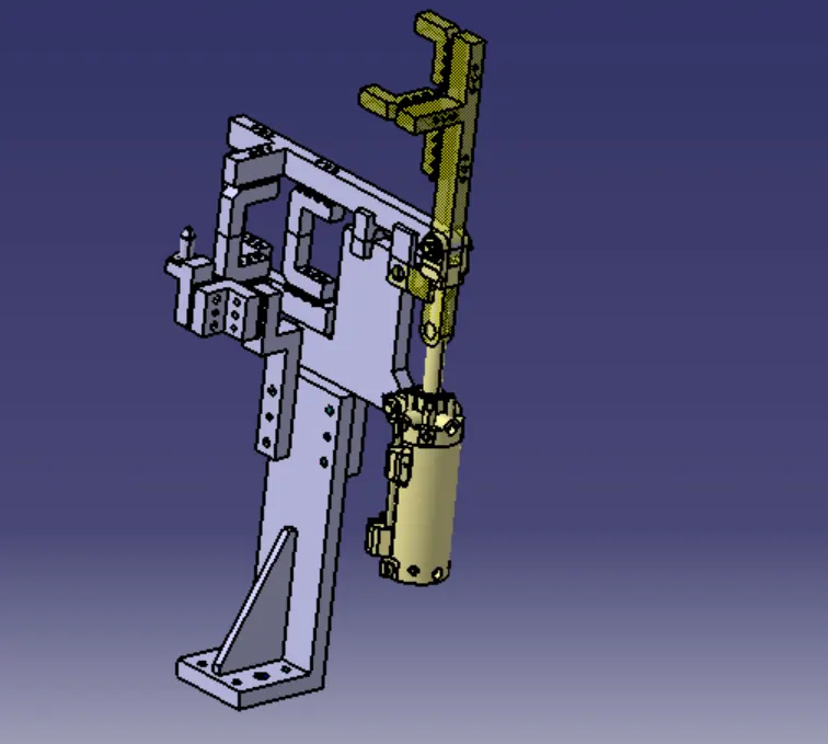
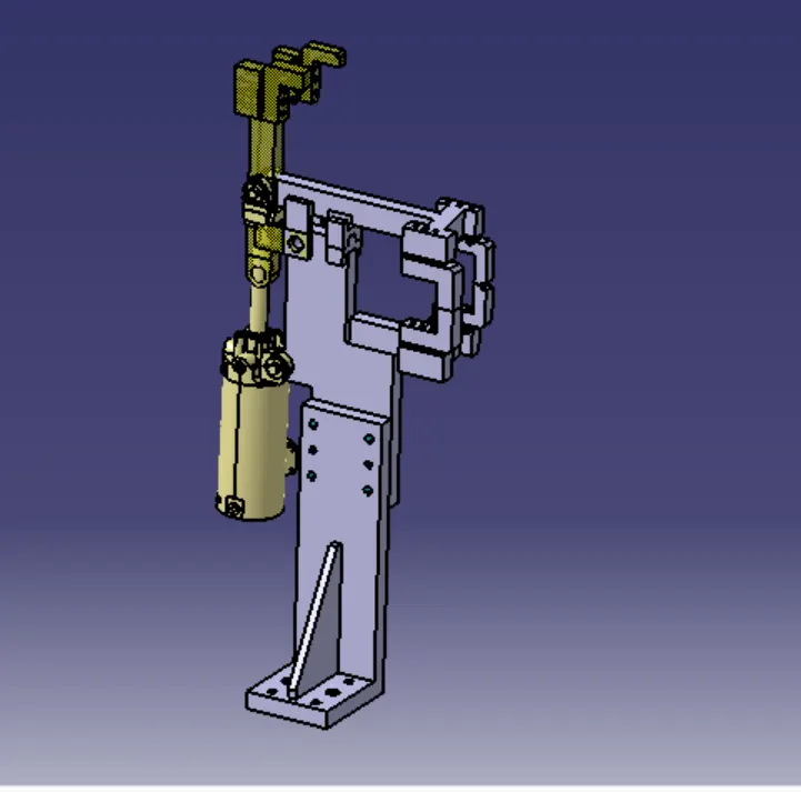
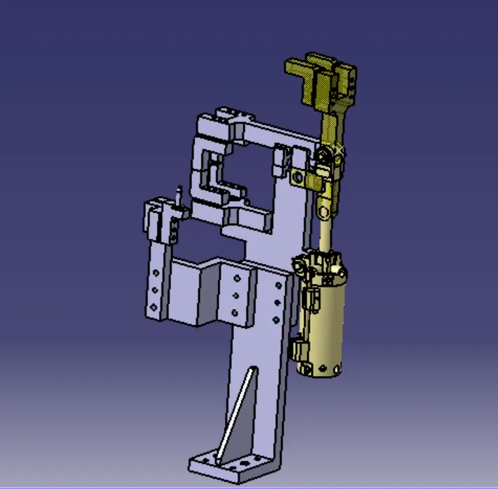
Below are the diffrent clamp units and units with pin attachment:-
- Unit name is P001_Z01_STO10_06_00_SWIVEL_CLAMP_UNIT with PIN
2.P001_Z001_STO10_07_00_SWIVEL_CLAMP_UNIT
3.P001_Z01_04_00_SWIVEL_CLAMP_UNIT WITH PIN
Structuring a design tree:
Structuring a design tree implies process where all the assemblies & parts are named in specific manner. Diff errant customers have different set of standards like how to structure a design tree? So, they will give standard template based on that design tree structured, which helps us to identify specific part of assembly. It specifies the Project number, station number, unit number; part number of each component so that it is easy to identify the parts.It is an important process which helps us to identify a specific part or assembly as to which project, tool or unit, it belongs to.
This helps us to avoid error during design study, manufacturing, assembly, Inspection etc.If parts or assemblies are not named properly or the design tree is not structured properly, it will create confusion to understand & create major possibilities of making an error.Naming of a fixture, a unit or a part gives the information as to which project or zone or assembly they do belong.It can help us to identify quantity of items of same type or diff errant types that are being used in assembly for e.g. bolt. It actually tells you how many bolts are particularly required in that assembly or unit.
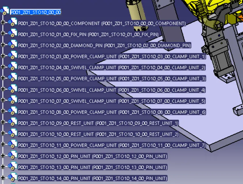
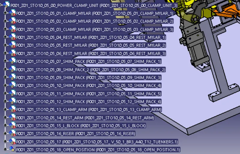
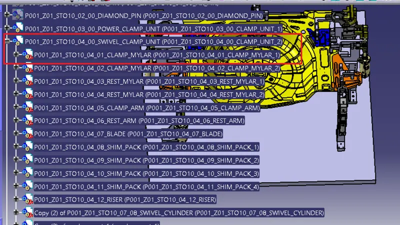
For e.g.as in below figure hignlighted in blue
P001 stands for project no 1.
Z01 stands for zone no 1.
STO10 stands for station no 10.
04 stands for unit no.
01 stands for part no. e.g.clamp mylar
All clamp units :-
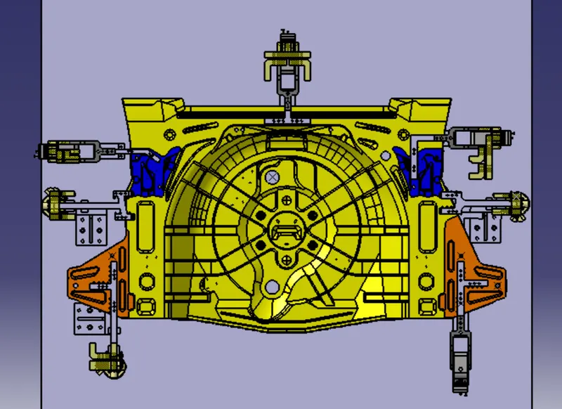
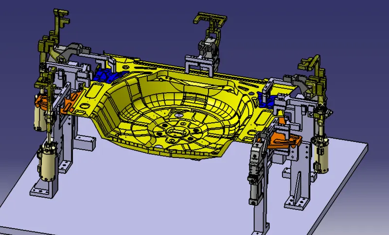
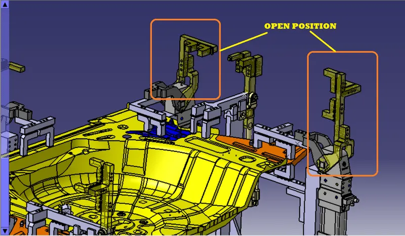
In above figure the yellow transperant parts shows the open positions of clamp.
Conclusion:-
Thus i have designed 3 different types of clevis clamp unit with different riser,blade,and clamp arm for a given car panel and unit which consist of both clamp unit and a pin unit combined.