Week 6:- Clamp Unit & Pin-Clamp Unit Design Challenge
DESIGN OF CLAMP UNIT & PIN-CLAMP UNIT
OBJECTIVE
To design three types of Swivel Clamp units and one Pin-Clamp unit, each featuring different risers, blades, and clamp arms, while ensuring the cylinder stroke remains at 100mm.
ABSTRACT
In the automotive industry, multiple processes are involved in manufacturing a single panel, followed by additional operations on both the panel and other components to create a complete automobile. A BIW (Body in White) fixture design engineer's responsibility is to create fixtures that securely hold panels for various operations. A fixture is a device used to support and position the workpiece precisely during the manufacturing process. In the automotive sector, a fixture consists of multiple units such as rest pins, fixed pins, retractable pins, clamp units, rough locators, sensor units, and base units. This project focuses on designing Swivel Clamp and Pin-Clamp units. The report covers an overview of fixtures, the 3-2-1 principle, key definitions related to the clamp unit and its components, tools used during the design process, methodology, and other essential explanations. Using the Catia V5 software
WORKBENCH USED
- Sketcher Workbench
- Part Workbench
- Assembly Workbench
TOOLS USED
- Sketching tools
- Translational tools
- Pad
- Hole
- Manipulation tool
- Snap and Smart Move tool
INTRODUCTION
A fixture is a work-holding device designed to support and accurately position a workpiece during operations. Its primary purpose is to secure the workpiece, ensuring repeatability, accuracy, and interchangeability in the manufacturing process.
A clamp unit is used to secure a panel in place, preventing unintended movement during operations. The clamp design is based on a customer-provided clamping plan, which indicates the locations for clamping. To understand how the clamp unit effectively restricts the panel's movement, it is important to grasp the 3-2-1 principle.
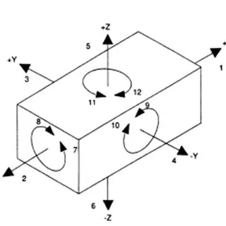
The 3-2-1 Principle states that six locators are enough to limit the necessary degrees of freedom of any workpiece. These locators, in combination with clamps, restrict motion. For example, three pins can restrict five types of motion, while six pins can restrict nine. To elaborate, when a workpiece is not clamped, it can move or rotate in multiple directions. The potential movements include:
- Translational motion along the x-axis
- Translational motion along the y-axis
- Translational motion along the z-axis
- Rotational motion around the x-axis
- Rotational motion around the y-axis
- Rotational motion around the z-axis
DEGREE OF FREEDOM
There are not only 6 degrees of freedom (DOF) but actually 12, as motion can occur in both positive and negative directions, as well as in clockwise and counter-clockwise rotations. However, to perform any operation on a workpiece, it is crucial to restrict its movements to ensure accurate results. This can be achieved using the 3-2-1 principle.
In the 3-2-1 principle, locating pins are used in a specific sequence to secure the workpiece on a fixture,
Three pins are positioned on the bottom of the component. These pins restrict:
- Translational motion along the z-axis.
- Rotational motion around the x-axis and y-axis.
This restricts 3 degrees of freedom.
However, the workpiece can still rotate around the z-axis and translate along the x-axis and y-axis.
Two pins are placed on the back side of the component. These pins constrain:
- Translational motion along the x-axis.
Rotational motion around the z-axis.
This brings the total restricted degrees of freedom to 5. The workpiece can still translate along the y-axis.
One pin is located on the adjacent side of the two back pins. This final pin restricts:
Translational motion along the y-axis.
With this pin, all 6 degrees of freedom (translational and rotational) are effectively constrained, and the workpiece is firmly held in place for machining or other operations.
This arrangement, using the 3-2-1 principle, ensures that the workpiece is securely located with minimal movement, allowing for precise and repeatable operations.
CLAMP UNIT
In a clamp unit, Clamping Mylar and Rest Mylar are used to accurately position and hold the panel in place. The functions they perform are as follows:
- Restricting upward and downward motion (translational movement along the z-axis).
- Restricting clockwise and counter-clockwise rotation around the x-axis.
- Restricting clockwise and counter-clockwise rotation around the y-axis.
By clamping the panel, we effectively restrict 3 degrees of freedom out of the total 6. This ensures that the panel is securely held, preventing unwanted movement during the operation. Similarly, when the panel is located using locating pins, the following restrictions occur:
- Translational movement along the x-axis is constrained.
- Translational movement along the y-axis is constrained.
- Rotational movement along the x-axis is restricted.
- Rotational movement along the y-axis is restricted.
With these restrictions, 4 degrees of freedom are effectively controlled, ensuring the panel remains in its exact position for accurate processing or assembly operations.
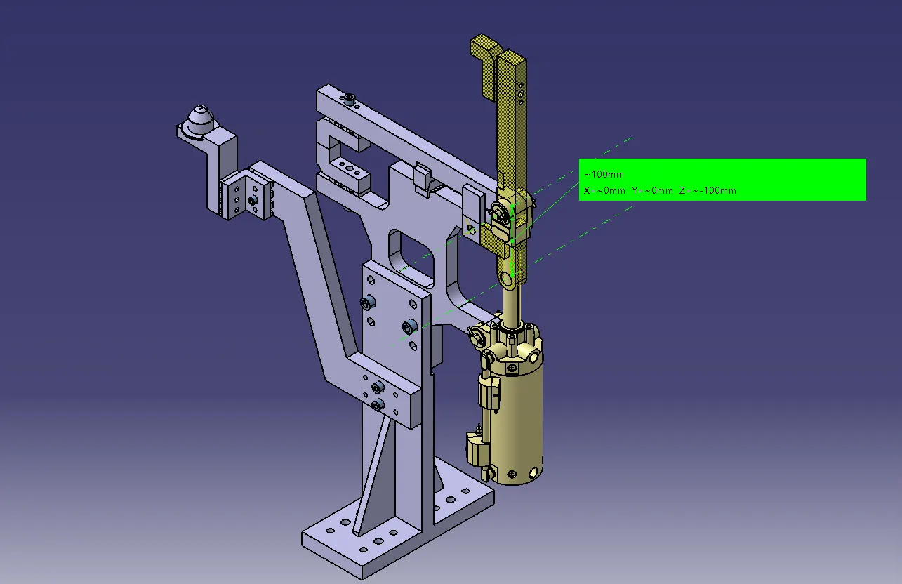
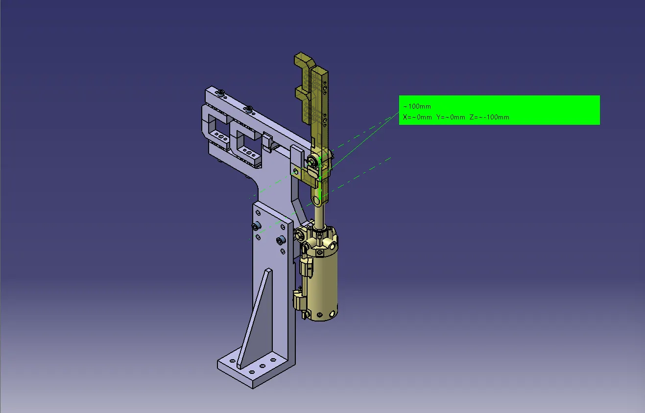
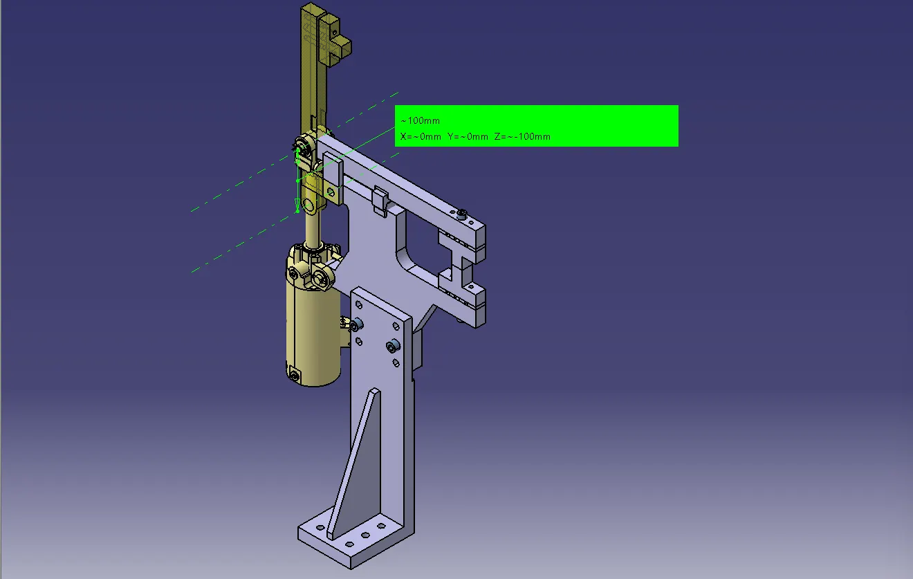
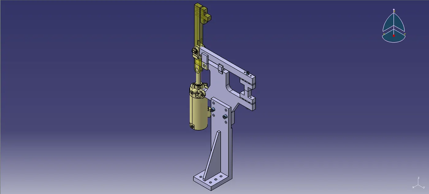
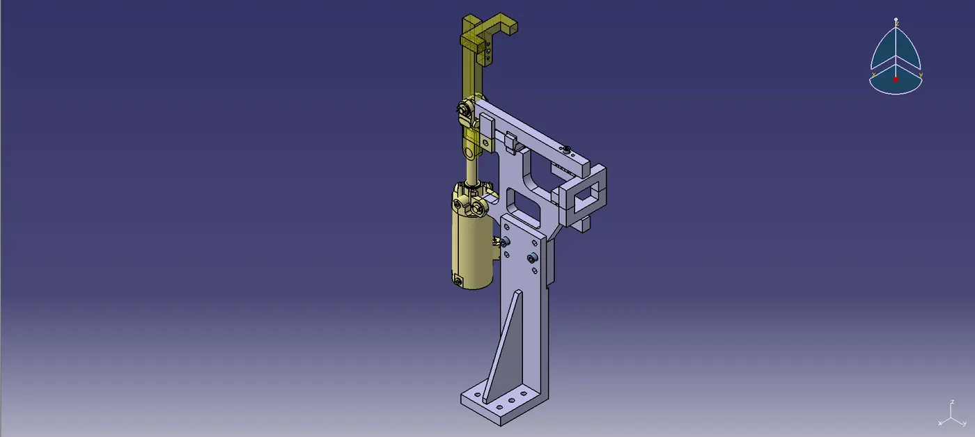
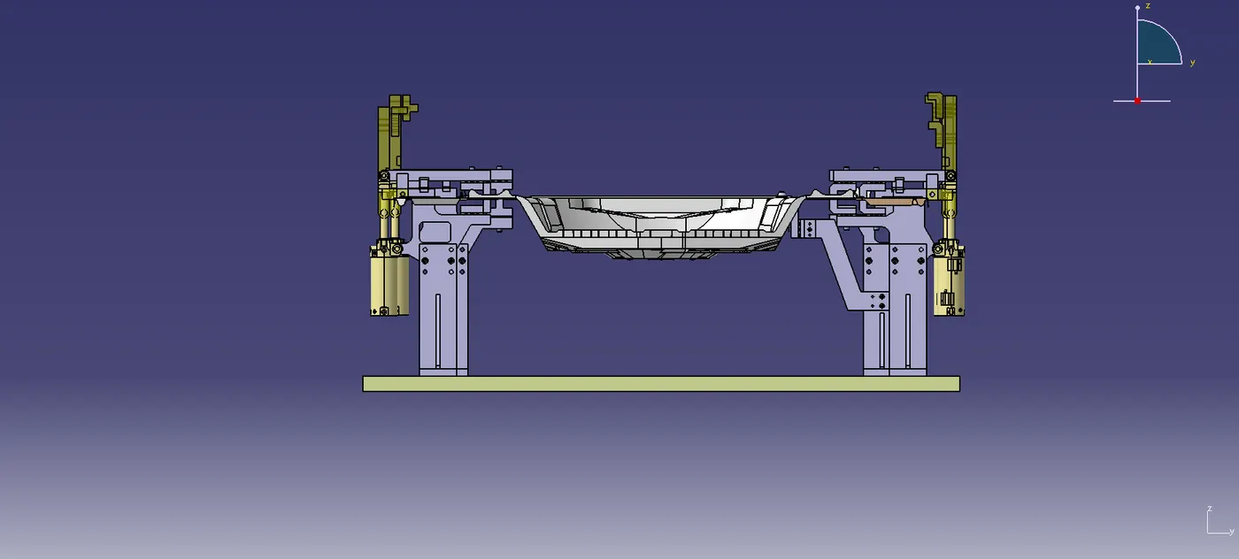
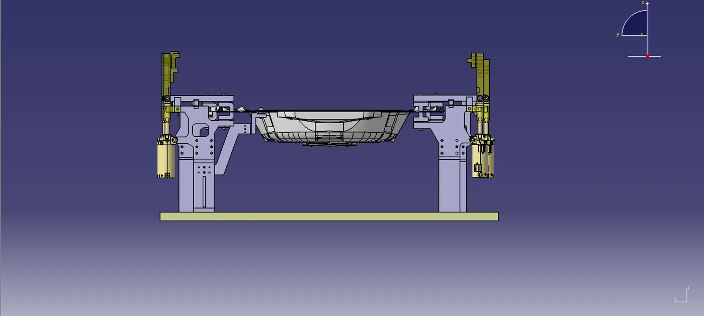
The stroke is maintained as 100mm. Images given below the 100mm stroke.
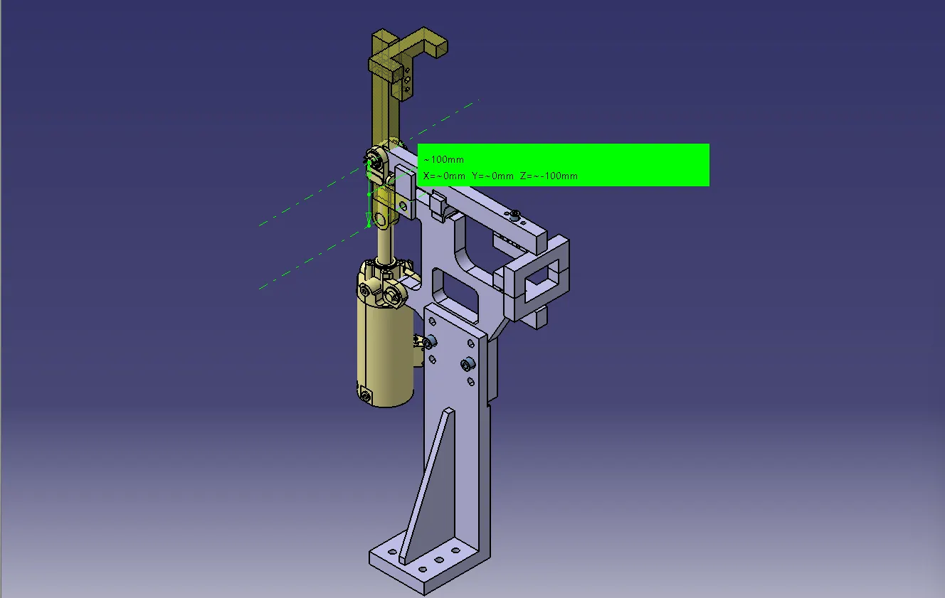
Components of Swivel Clamp unit & Pin Clamp unit
NC blocks
NC block is fastened to the cylinder's clamp arm. The automobile panel was held in place by pressing it up against the rest. Another name for it is Clamp Mylar.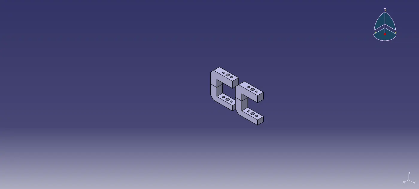

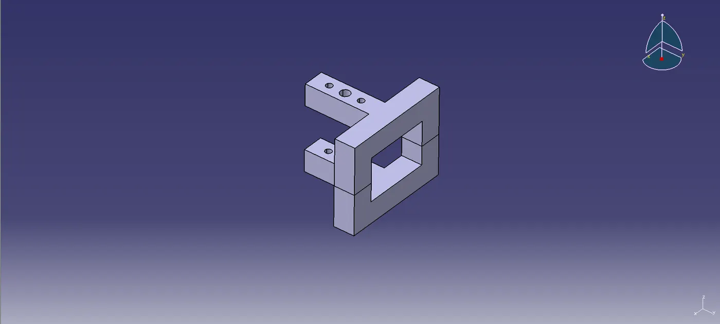
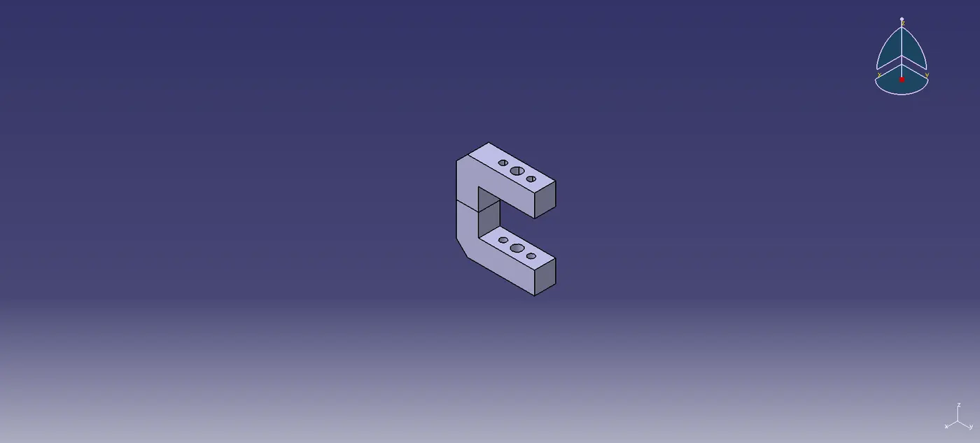
Clamp arm
The section of a cylinder to which all of the moving parts are attached is called the clamp arm. It's a purchased portion.
Swivel cylinder
A pneumatic device that uses pressured air is a swivel cylinder. Here, a Clevis cylinder is being used. Its dimensions are 63 mm for the bore, 19.5mm for the breadth, and 100 mm for the stroke. It is employed to open and close the clamp arm-attached components. It's a purchased portion.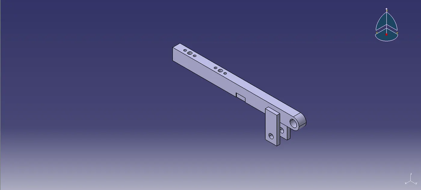
Stopper
Here, Stopper are used to hold up the clamp arm. Both a male and a female component are present.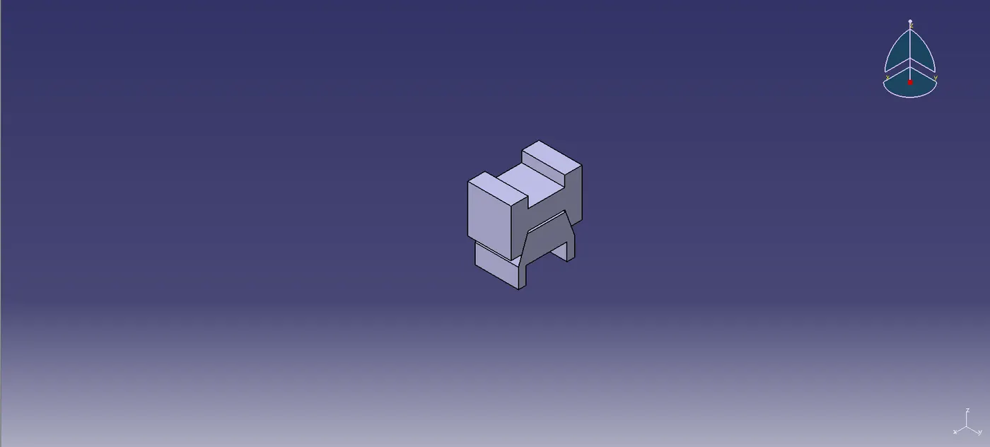
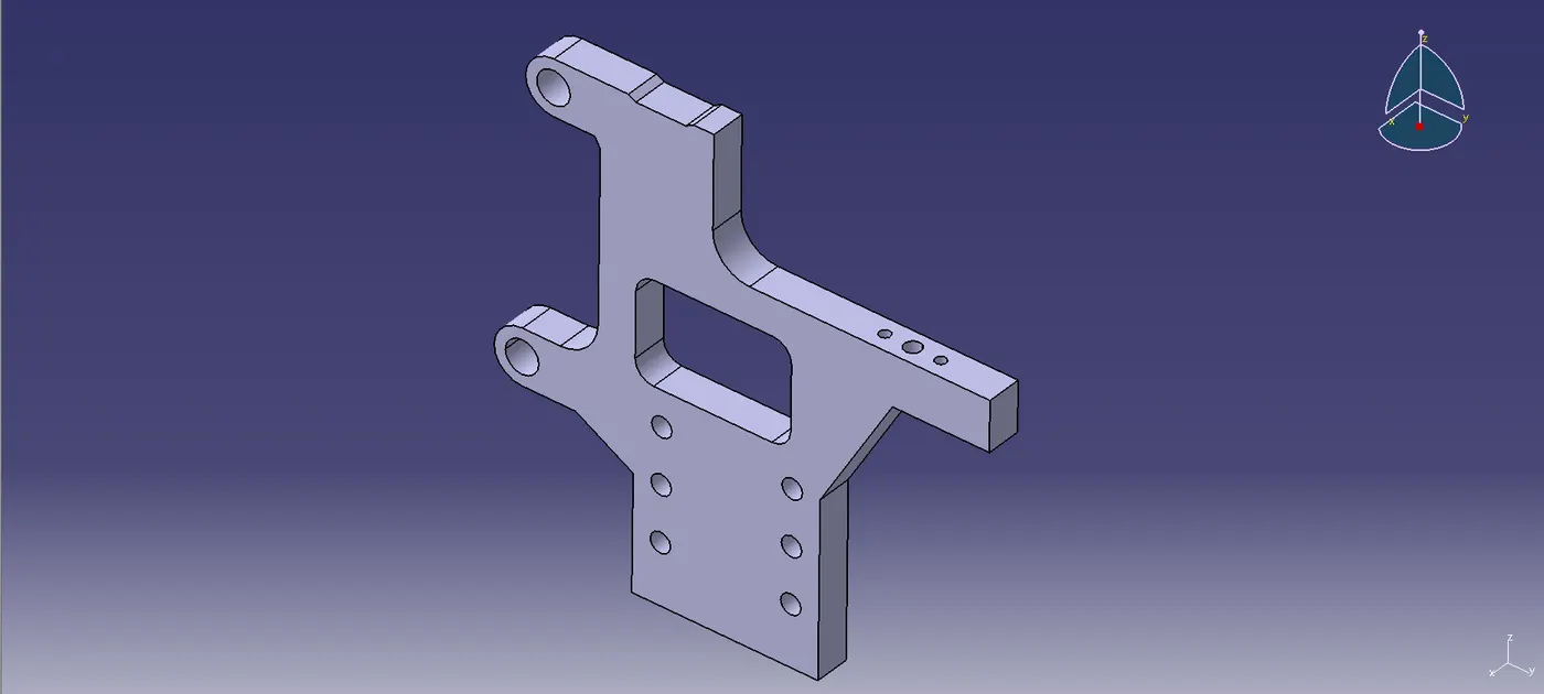
Blade
Blade is an optional block that can be utilized in accordance with the specifications of the design. The component that joins the complete unit to the riser block is called the blade. It may be a standard part or a made part.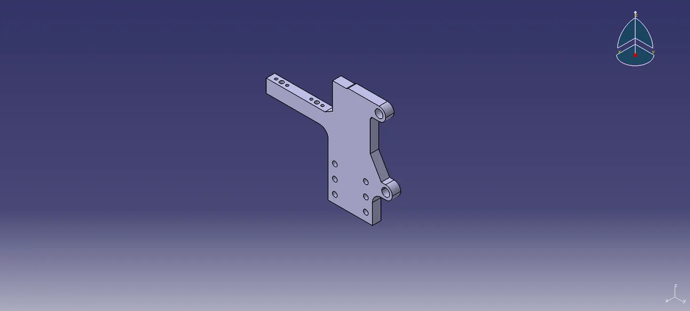
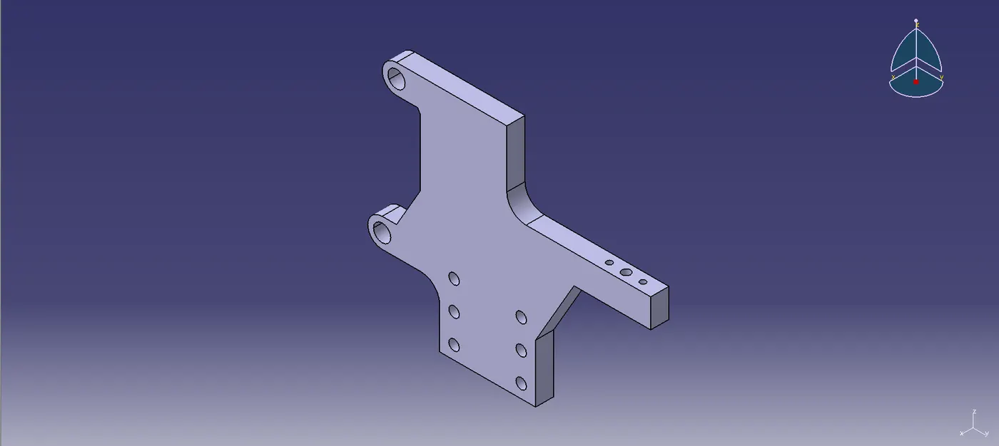
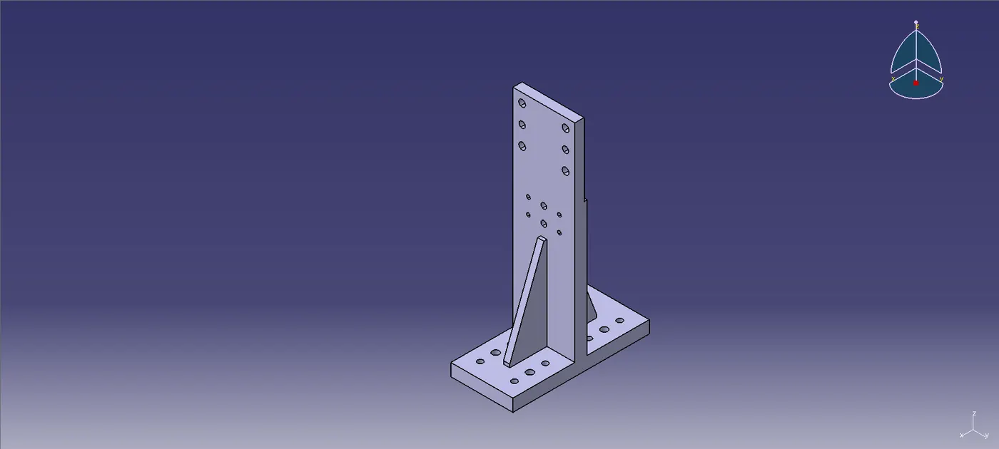
Riser
The component that all of the units are mounted on is the riser. It fastens itself to the base and supports the unit. It may be a standard part or a made part.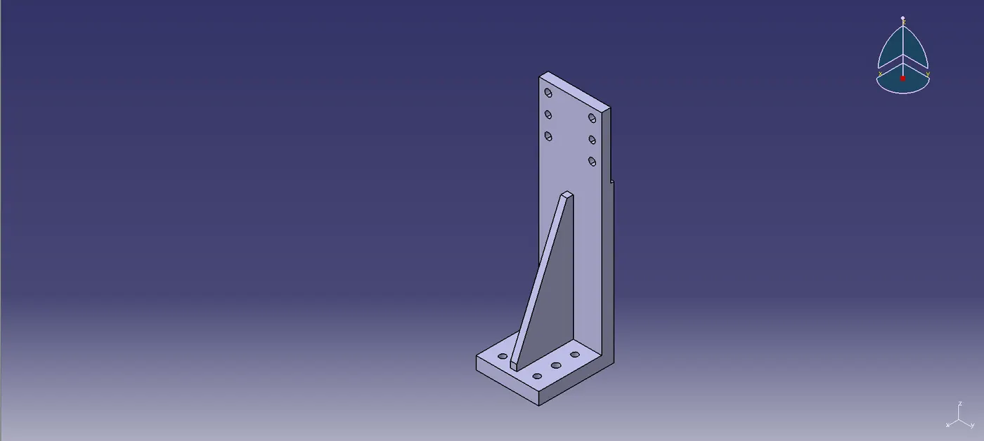
Bush
Pins are inserted into holes using a bush.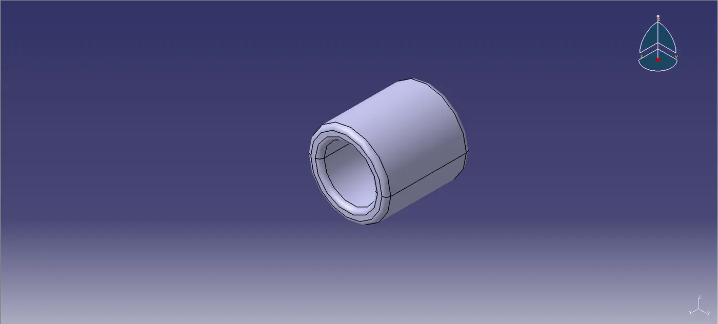
Shims
Shims are employed to help locators adjust. These are standard pieces in general. Shim blocks can be modified to account for variations in production.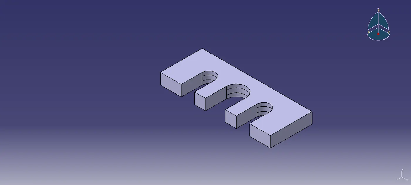
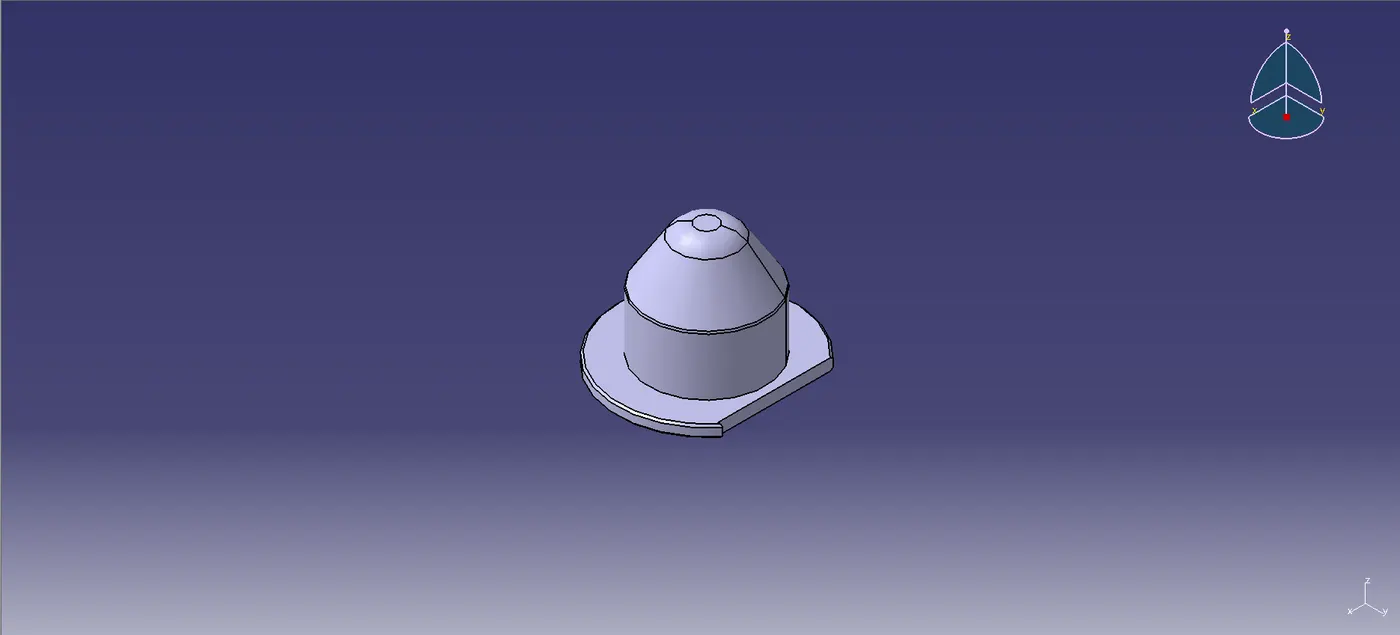
- Pin
Pin retainer
The component that keeps the pin in place is called a pin retainer. It limits the mounted pin's ability to rotate. It may be a standard part or a made part. To attach the pin, the pin retainer needs to have a hole in it. The pin must be installed on a machine-machined surface. To lock the pin's rotation, it needs to have a step. It is necessary to machine the surface where the blocks are mounted. A block can be used to secure it with the riser.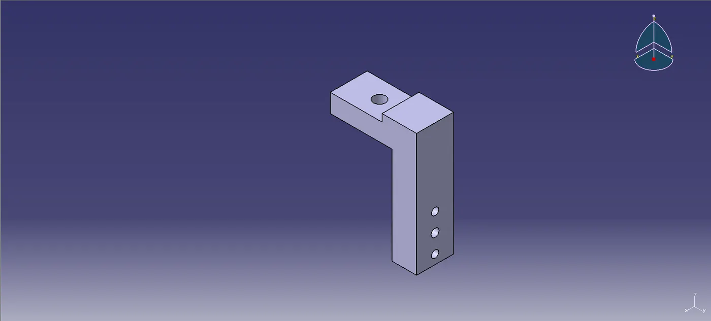
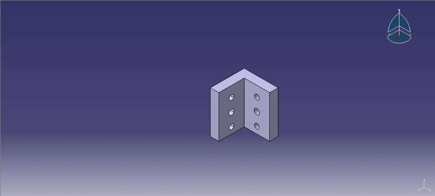
- Pin Block
PIN LOCATION
Locating pins are crucial for the controlled and precise positioning of a workpiece, especially when fine tolerance is required. For instance, in a scenario where a pallet moves along a single axis, and the drive mechanism lacks the necessary accuracy or stability to position it precisely for a particular process, locating pins can provide an effective solution. Typically, two locating pins are sufficient to properly locate a workpiece on a single plane.
When selecting locating pins, it’s essential to consider the following guidelines:
Engagement Depth
The pin should engage 3-5mm from the car part’s entry surface to ensure proper fit and stability.Adjustable Shims
All locating pins should be paired with 2-way adjustable shims, regardless of the direction in which the movement is being arrested. This allows for fine-tuning and flexibility in positioning.Pin Type for 4-Way Arresting
Round pins should be used if the hole is round and the workpiece requires 4-way arresting (i.e., arresting movement along both translational and rotational axes in all directions). Diamond pins should be used if the hole is slotted and the workpiece needs 4-way arresting.Pin Type for 2-Way Arresting
Round pins can be used for 2-way arresting if the hole is slotted. Diamond pins can be used for 2-way arresting if the hole is round.
These considerations ensure that the workpiece is accurately and securely positioned, minimizing the risk of misalignment during operations. Proper pin selection and setup are key to achieving high precision and repeatability in the manufacturing process.
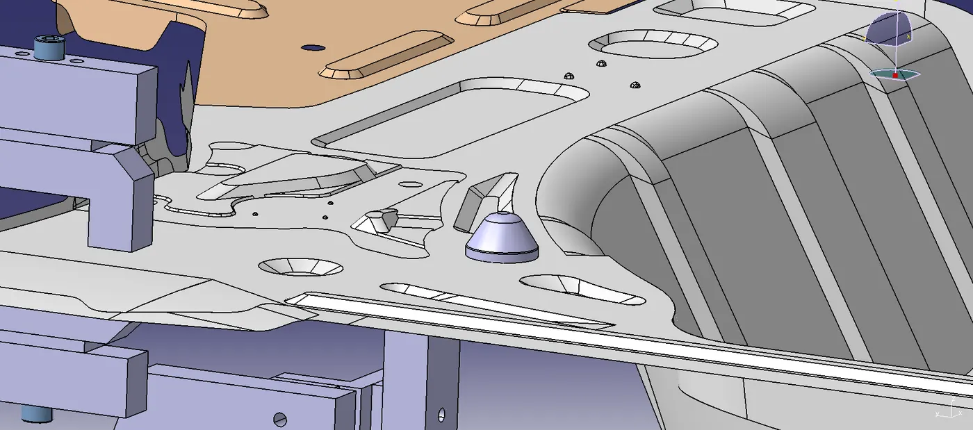
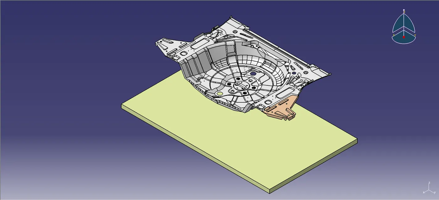
CAR PANEL
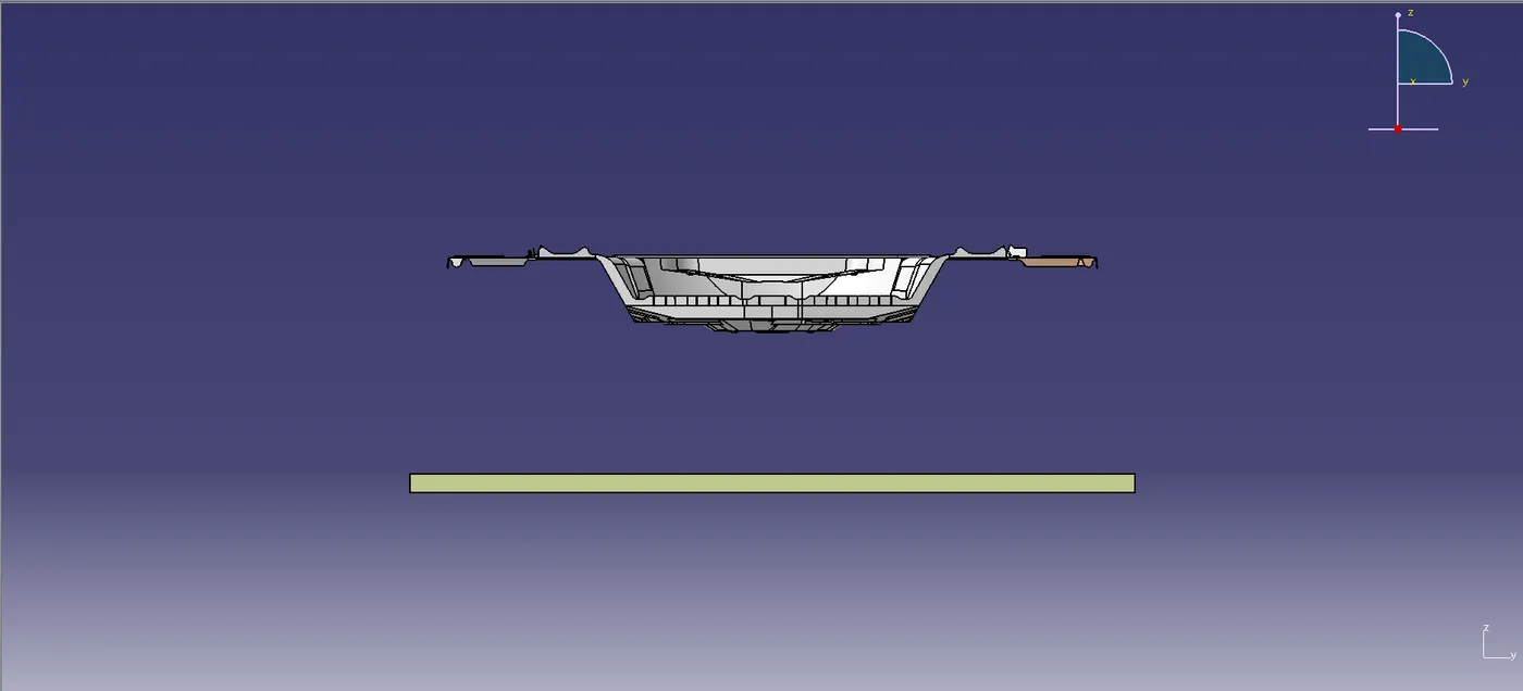
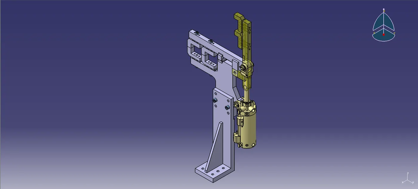
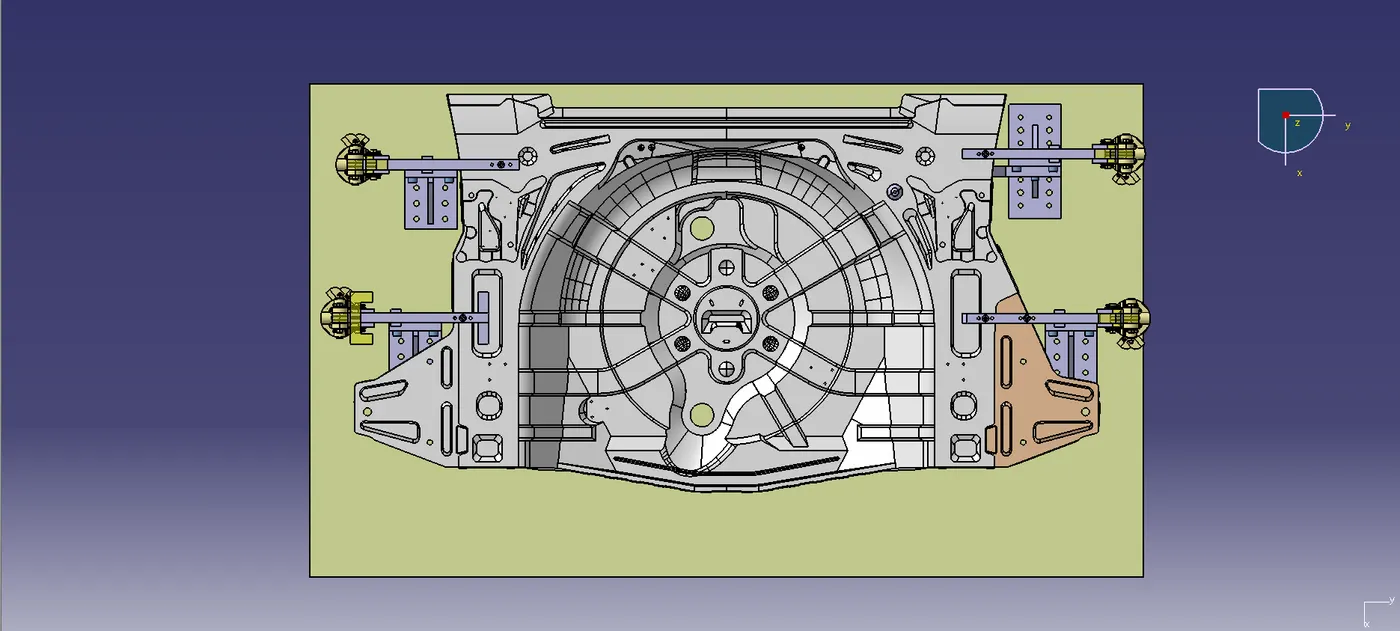
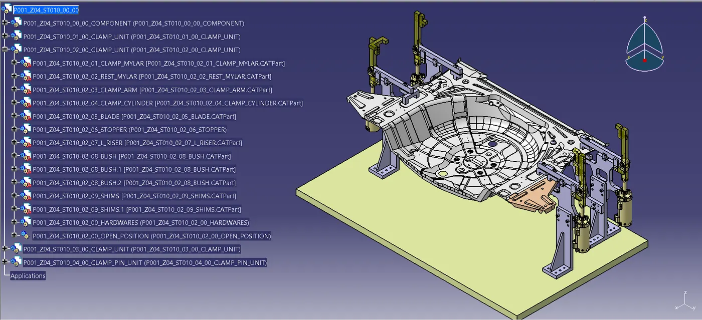
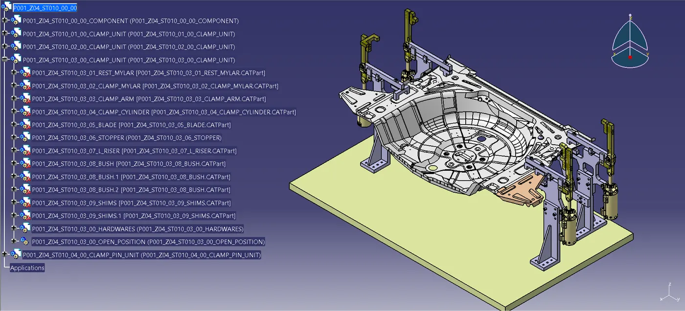
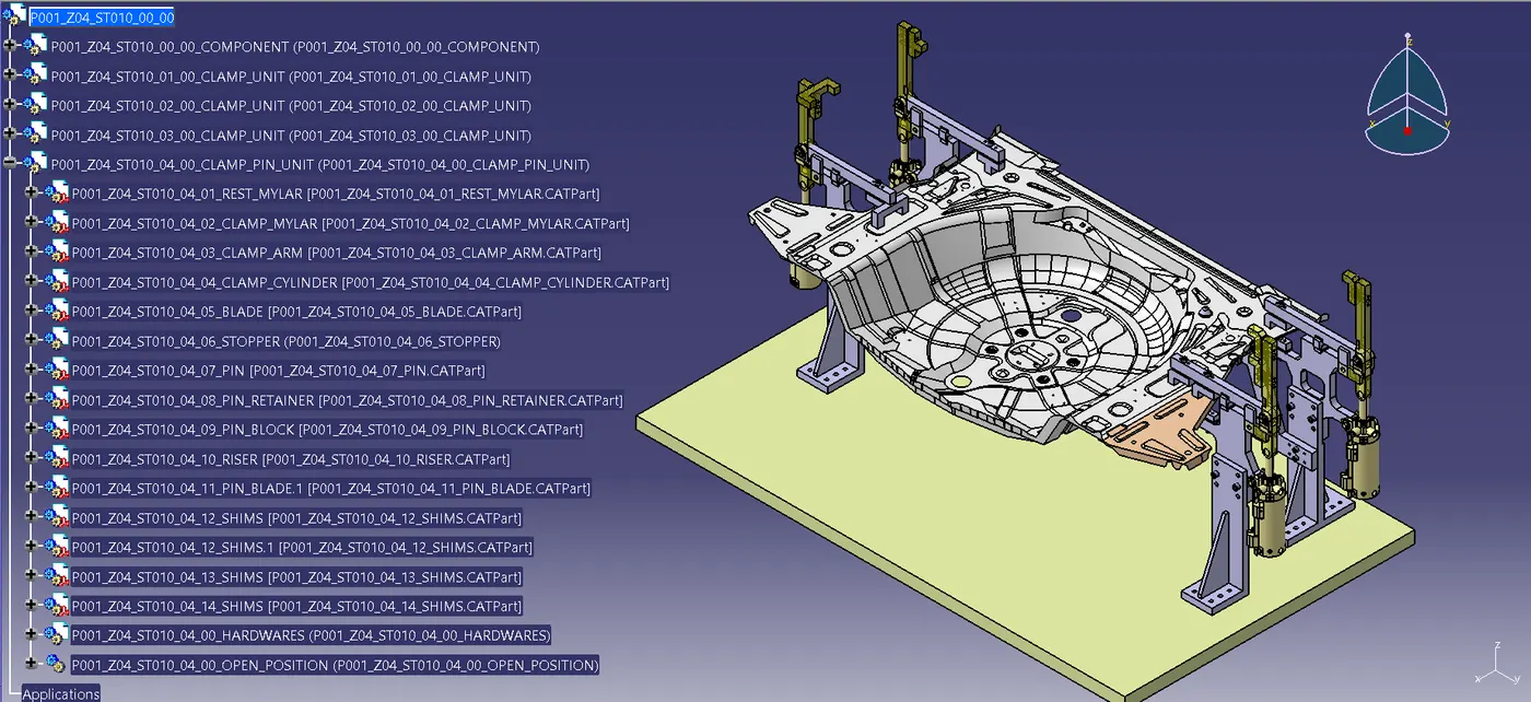
CLAMP UNIT & PIN CLAMP UNIT
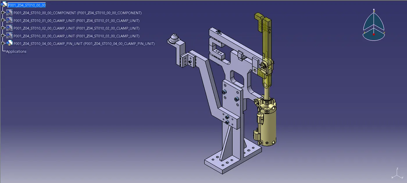
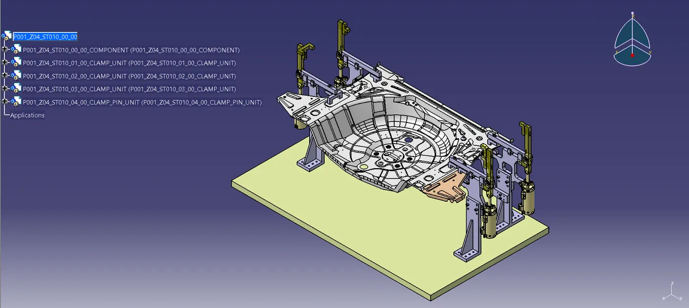
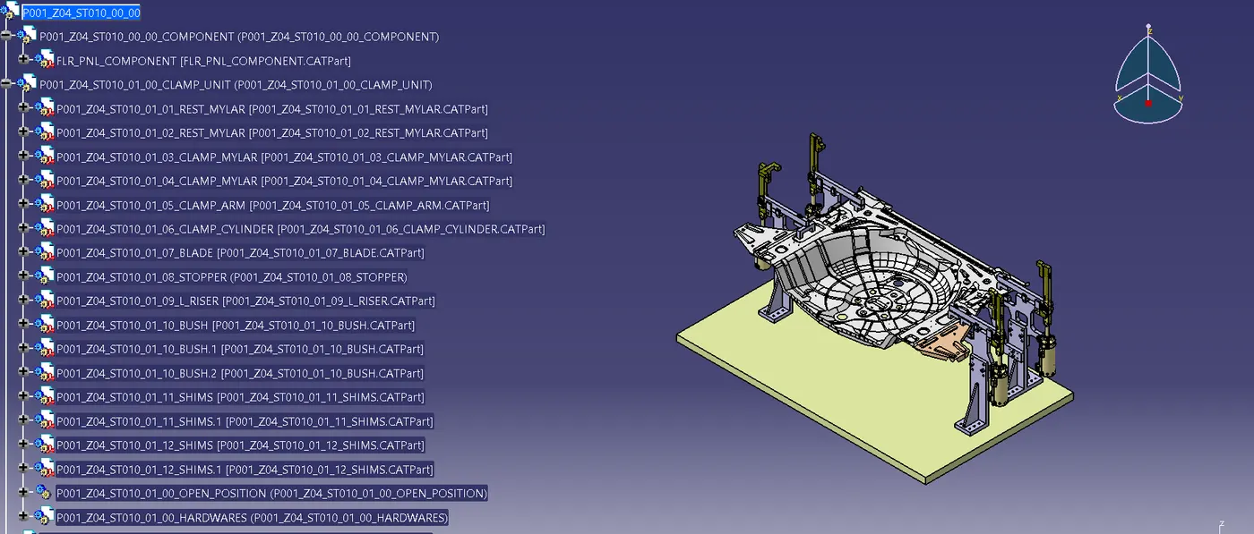
FEATURE TREE
CONCLUSION
The Swivel Clamp unit was made using the right design techniques. The Pin Clamp unit was made using the right design techniques. Attached were the necessary part files and photos.