Week 6:- Clamp Unit & Pin-Clamp Unit Design Challenge
CLAMP UNIT & PIN CLAMP UNIT
Aim:
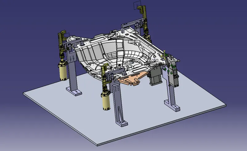
The aim of this project is to design 3 Swivel clamp units and a Pin-clamp unit for the given car panel along with different risers, blades and mylars.
Objective:
In this project, 3 different swivel clamp units are designed with different risers, blades,mylars along with a pin-clamp by using power clamp. For the swivel clamp units swivel type cylinders are used. The stroke of the cylinder is maintained as 100 mm. The design is done considering the fundamentals of pin unit design and 3-2-1 principle along with the clamping forces of the cylinder.
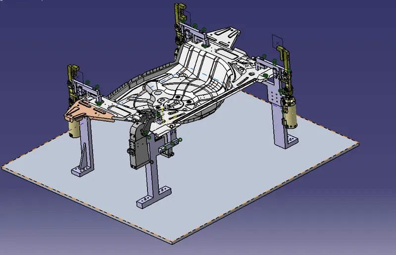
Clamp unit:
- A clamp unit is a unit designed to clamp/hold the car panel with NC blocks/Mylars/Rest by using a pneumatic clamping cylinder.
- Some of the parts of the clamp unit is clamp arm, finger, rest/backup, L-block, shims, Risers and Pneumatic cylinders.
Types of clamp units:
- Power clamp unit
- Swivel cylinder clamp unit
Swivel clamp unit:
- Swivel clamp unit is designed to clamp/hold the car panel with clamp/rest mylar by using a pneumatic clamp cylinder.
- Clamp mylar is connected to pivoted clamp arm which is connected to the pneumatic cylinders. Down stroke of the cylinder opens the clamp.
- Usually clamp open posotion is 90 degreeUsually clamp open posotion is 90 degree.
- Swivel clamp consists of clamp/rest mylars, blade, clamp arm, stopper, pivot plate, riser and shims.
Fundamentals of designing a clamp unit:
- It is preferred to design clamp unit with pivot centerline in-line with clamp surface. When possible upto 25mm offset can be acceptable.
- For sigle angular clamping, it is recommended that the centerline of clamp pivot be positioned on plane that is created by surface being clamped, upto 15 degree off normal pivot location can be used in extreme cases where recommended clamping condition cannot be satisfied.
- There should be adequate space between the cylinder & the riser to allow the swinging motion of the cylinder while i & l iopening & closing.
- Clamp-pin unit is used where it is necessary to locate 2 panels for operations like welding.
- All parts should snap & butt properly to each other.
- Maintain a distance of 10mm to 12mm between the panel and other clamp parts.
- Avoid any clash to prevent issues at assembly.
Parts of Swevel clamp unit:
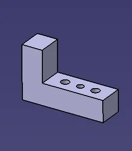
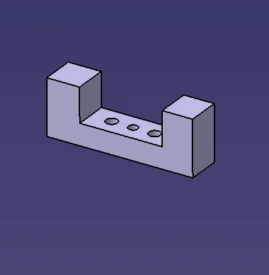
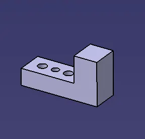
- Finger /clamp mylar:
- It is a NC block mounted on the clamp arm of the cylinder.
- It is used for clamping / holding the car panel
- It presses the car panel towards the rest.
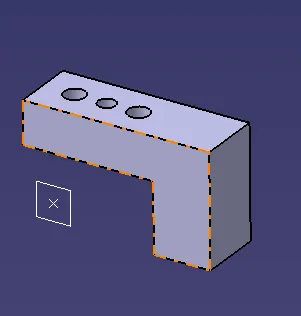
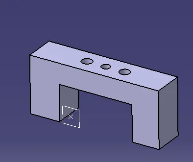
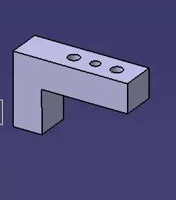
2. Backup / Rest Mylar:
- It is a NC block fixed to the unit to support the car panel.
- It helps in resisting the clamping force of cylinder onto the panel, thus clamping is achieved.
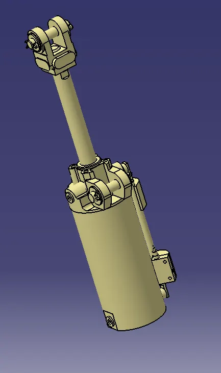
3. Clamp cylinder:
- Clamp cylinder is a pneumatic device which works with the flow of pressurised air.
- Clamp cylinder is a brought out part and some manufacturers are destaco, tuenkers, etc.,
4. Stopper:
- The main function of the stopper is to restrict the motion of the clamp arm beyond the blade or the limit.
- The stopper will be mounted between the clamp arm and the rest/blade.
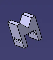
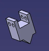
5. Clamp Arm:
- A Clamp arm is a make part, it is made as per the positioning of the clamping cylinder, Stopper and shims. Clamp arm is made from Hard material.
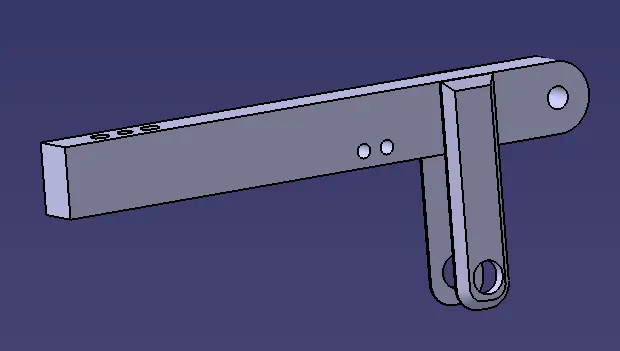
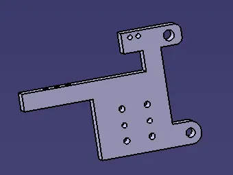
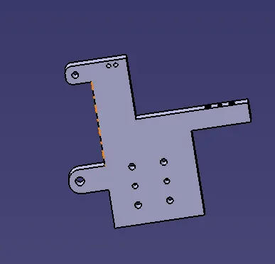
6. Blade/Block:
- A blade is a make part designed according to the position of the riser, clamp cylinder, Clamp arm, Rest Mylar and stopper
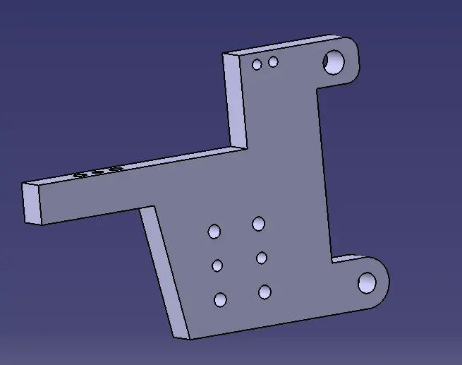
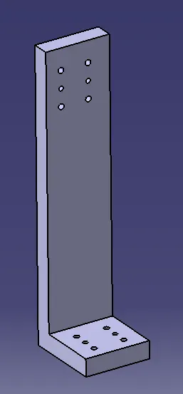
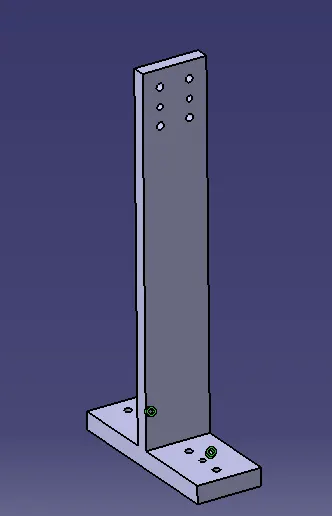
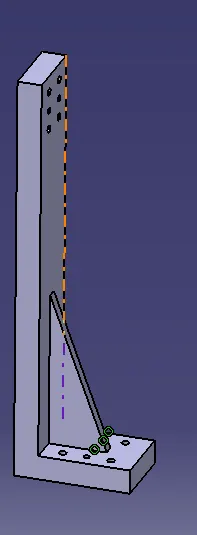
7. Riser:
- A Riser is a standard part or a make part which provides height to the pin unit, Clamp unit as per the requirements. Riser should have adequate strength so it can sustain the load of the car panel, Clamping cylinder, Blades.
8. Shim Plates:
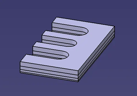
- In Fixture, we are providing tolerance to each part mostly manufactured. Those tolerances tend to stack up and Reflect together. In order to avoid that we use shims so we can easily adjust after assembly so whatever stack up there we will rectify it through shims. Shims come in thickness of 0.5, 1, 1.5, 2 etc.
- We provide shim to accommodate clamp as well as rest mylar in two directions. Clamp & rest mylar can be adjusted in one direction only i.e., up or down. Also, two-way shim provided for locating pin to accommodate adjustment.
Design of Swivel Clamp unit:
- Study the PLP (Principal location Points) data along with the nearby spot data.
- Depending on the angle of cross section. Mylars will be having shimming either in one direction or in 2 directions. General thumb rule if the section is inclined more than 15 or clamping surface is 3D profile then 2 direction shimming are provided.
- Take an overview of the working height if you're having manual welding. For robotic welding also it's important to see the working height in consideration of the robotic gun, turntable height if manual loading is done.
- Put the proper gun at the spot location. If process engineer has gun shape stick to X, C or Y type of gun. Do the proper gun study and place the gun as per the Geo or re-spot decision and operator approach. Once basic gun is placed considering the throat depth and throat gap start building the clamp and rest block at the PLP.
- Panel section creation: Take a section at PLP either in clamp opening direction or normal direction Sections should be normal to base. Panel section through X, Y or Z direction passing through PLR Section will help it finalizing the shape of clamp and rest block. Most importantly used for finalization of gun shape.
- Finalization of a base plate plane: Consider following things before deciding the base plate Height of maximum and minimum weld spot from the floor. No gun arm should touch the base plate. Operator ergonomic while accessing all the spots.
- Construction of Rest and Clamp block: If standard Mylar has to be used (Few companies make standard height and length of steel blank with few holes and dowels for clamping) they select the proper blank size as per the requirement consider 0.5 mm above the panel.
- Select the clamping cylinder as per the pivot point distance from the PLP Once clamp and rest block are built, start construction of mounting plate or lubrication structure as per the company standard to make the connection with the base plate, shimming is 2mm solid+3mm shim pack. In few companies 3 shims are used. Make connection plate between rise and Mylar Material can be C45, Teflon, Aluminium or S-Gurn as per the customer requirement Generally S Gurn Mylars are made of more thickness.
DESIGN OF SWIVEL CLAMP UNITS AND PIN CLAMP UNIT:
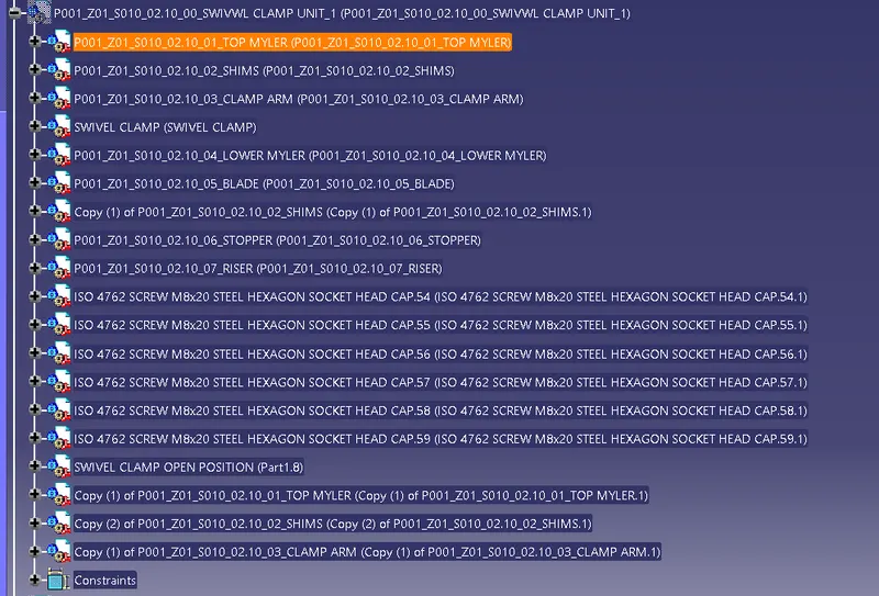
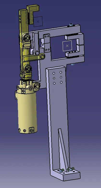
Design of Swivel clamp Unit1:
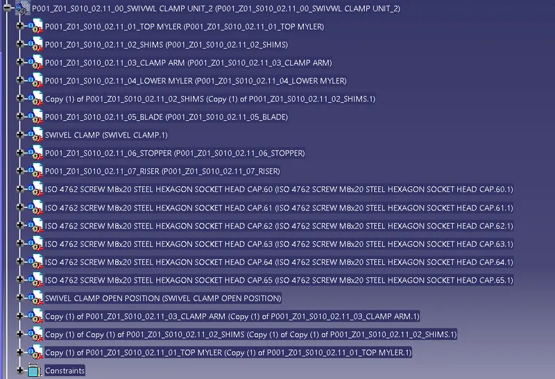
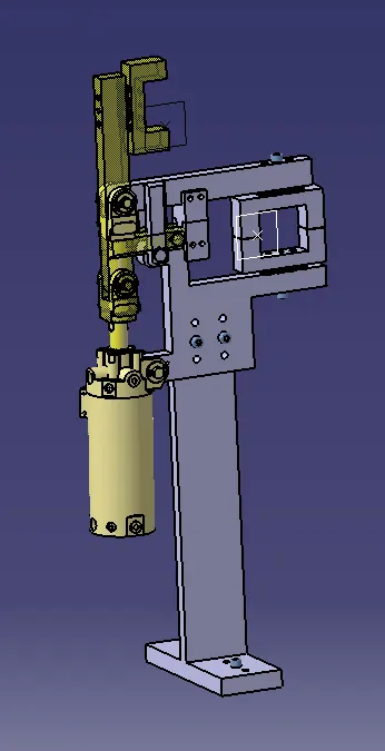
Design of Swivel Clamp Unit 2:
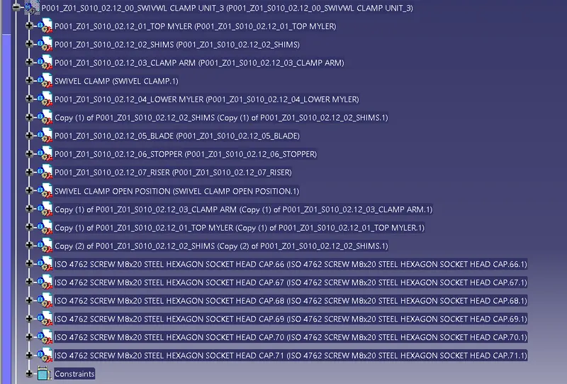
Design of Swivel Clamp Unit 3:
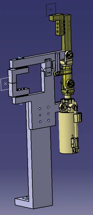
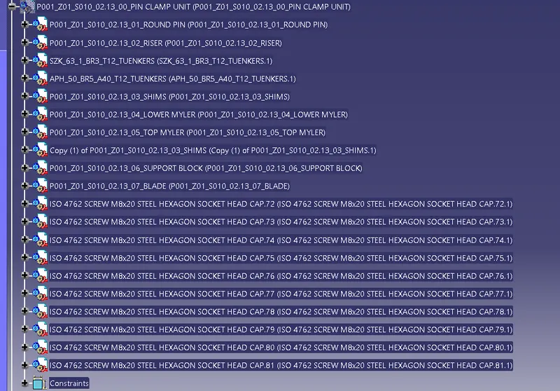
Design of Pin Clamp Unit:
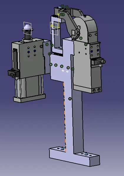
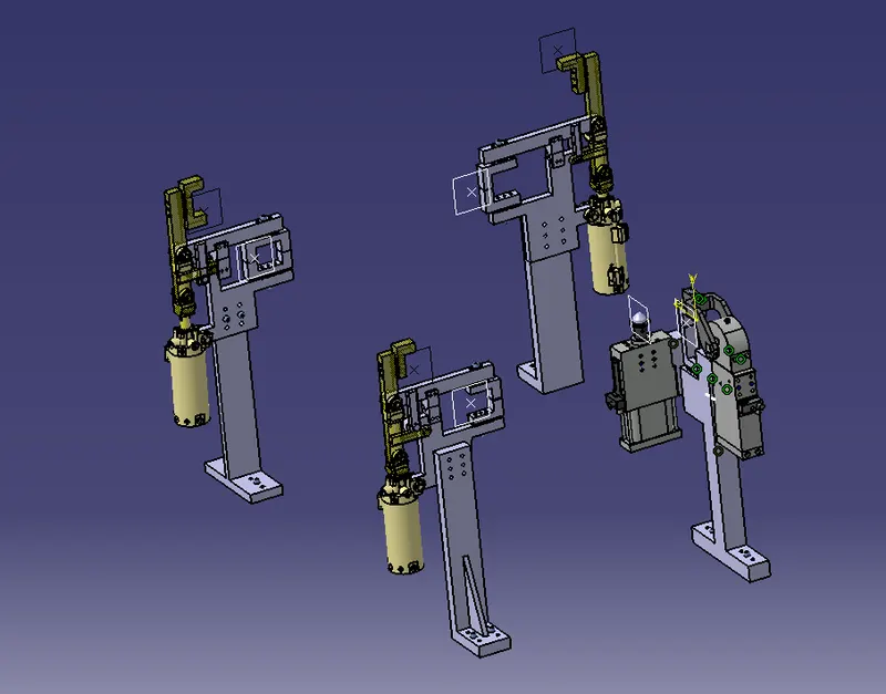
Structure of Design tree:
- A process where all the assemblies and parts are named in a specific standard Different customer have different set of standards and the structure of design tree.
- Every company, every customer has different standards of their own structural design tree.
- So, they will be giving a template on how the structuring and detailing of the design is done. And you have to follow that particular designing or structuring of the tree.
- In the design tree itself if we mentioned that particular name, wherever that part is we can easily know that this part belongs to this one or this station or this assembly on particular unit. So, this helps us to avoid errors during the design study, manufacturing assembly and inspections.
- It is an important process which helps us to identify a specific part or assembly as to which project, tool, it belongs to.
- Structuring a design tree is actually to avoid the errors, which might come during manufacturing assembly, or either in house inspections as well.
- If the part, or assembly are not named properly, or design tree is not structured properly, it will create confusion to understand the design and may create major possibilities of making an error.
- Every part, every component should be named according to their procedures.
- If we did a mistake or renamed the entire standard parts from the customer as a design part. Now the customer is going to manufacture the entire part again from the scratch, but he already has that product in his itinerary. But extra cost extra time and is feasible. This is also known as an error which is actually going to increase the cost of the entire assembly as well.
- Naming a fixture or a unit or a part gives the information as to which project zone or assembly do, they belong.
- If we name the part properly or name the fixture properly ill actually tell which unit or which assembly or which zone or in which station it actually belongs.
- It can help us to identify the quantity of items of same types or different types that are being used in an assembly.
- While starting of designing a fixture, the first unit will be the base unit.
- In a Design tree, all the manufacturing parts should be first and the standard parts should be at the last.
- Design tree helps to study or understand the parts in the assembly easily