Week 6 - CHT Analysis on a Graphics card
Aim: To perform CHT analysis on graphic card
Introduction:
Conjugate Heat Transfer(CHT) is the combination of heat transfer in solids (where conduction is dominant) and heat transfer in fluids (where convection is dominant). CHT analysis is done whenever there is heat transfer between a solid body and fluid flow. A simple example of CHT analysis is a hot body immersed in a fluid flow which is the case in heat treatment of materials where appropriate cooling rate is required to attain the desired properties for the material. Here CHT analysis is necessary to control the cooling rate by predicting the heat transfer coefficient and to show the temperature variation of solid. CHT is also used in analysing the heat transfer in a heat exchanger. A heat exchanger is a system where heat is transferred between two fluids (may be of different phases) without mixing of these two fluids. A Shell and tube heat exchanger is a perfect example of CHT, here one fluid flows through tubes, and other fluid flows in the shell over the tubes. The heat is transferred from one fluid to the walls of the tube and then from the tube wall to other fluid. Here CHT analysis is useful for predicting the heat transfer coefficient and to improve the effective heat transfer rate. CHT is also used in analysing the cooling of electronic devices.
The term conjugate heat transfer (CHT) describes the processes which involve variations of temperature within solids and fluids, due to thermal interaction between the solids and fluids. The exchange of thermal energy between the two physical bodies is called study of Heat Transfer, the rate of transferred heat is directly proportional to the temperature difference between the bodies.
Conjugate heat transfer corresponds with the combination of heat transfer in solids and heat transfer in fluids. In solids, conduction often dominates whereas in fluids, convection usually dominates. Efficiently combining heat transfer in fluids and solids is the key to designing effective coolers, heaters, or heat exchangers. Forced convection is the most common way to achieve high heat transfer rate. In some applications, the performances are further improved by combining convection with phase change.
Heat transfer in solids and heat transfer in fluids are combined in the majority of applications. This is because fluids flow around solids or between solid walls, and because solids are usually immersed in a fluid.
THEORY :
In this project , A steady state conjugate heat transfer analysis on a Graphic card has become an everyday used object and a very important part of any computer system , laptops etc. This product is mass produced daily in millions and has made computers exceptionally efficient . As they consume electricity to operate and running a heavy software or graphically task on computer takes a payable use on its graphic card , because of which it generates a large amount of heat .
There is a limit to any system that can hold heat to keep its parts under safe operating condition . We cannot go past these limits as it will damage the system ,Cause failure of the product and system etc. But what we can do is measure to cool this system , cool the graphic card so the system keeps running at optimum speed & condition .
There are various methods of cooling electrical components , through fan , thermal pastes and gels , double fanning , using materials that help dissipating the heat in the fan’s direction , arrangements of components etc.
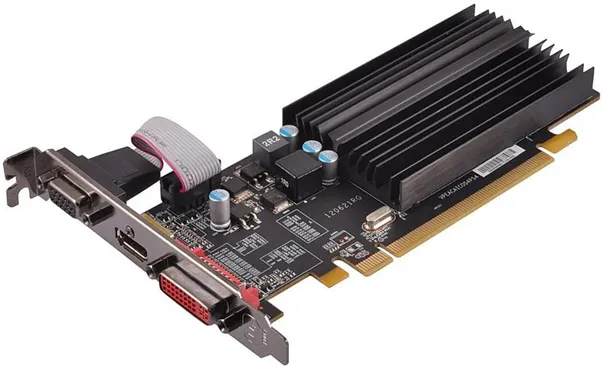
Cooling of graphic card , i.e by conduction in the PCB base & fins convection with the surrounding air by providing cooling fins over heat source (graphic card processor) which in turn try to remove heat through conduction and additional air is allowed to flow through assembled components which act as a phenomenon called forced convection.
In this simulation conjugate heat transfer analysis is done on graphic card model by applying heat on the processor of the graphic card while it contained in an enclosure . The air is passed at a certain velocity through the enclosure and we observe the heat dissipation through the fins by conduction from the processor , then observe how the flowing air cools the fins & observe the heat transfer taking place through it.
Practical applications of CHT problems are used to determine:
- Maximum and minimun temperature in various parts of the system.
- Temperature Distribution which is related to the thermal stress over a particular wall or system etc.
- Tempearture Response in time-dependent applications such as heating or cooling problem.
- Heat transfer co-efficient.
Spaceclaim Geometry:
Import the graphic card.stp file to the space claim geometry
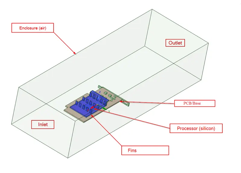
Topology is set to share such that the data could be shared between the different components of the graphics card.
Mesh:
Open mesh and name the inlet, outlet and symmetry wall(enclosure) as shown in the above figure
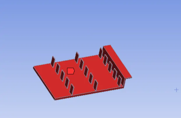 FINS
FINS
 PROCESSOR
 BASE/PCB
The components viz. PCB, processor and the fins were given body sizing as follows
Base line Mesh
A basic mesh is genertaed using the standard values recommended by Ansys. This mesh is used to obtain an initial solution which will help us to determine the location where mesh refinement is required.
1.Element Order: Linear
2.Element size: Default
3.Number of Nodes: 12627
4.Number of Elements: 52375
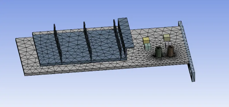
2.2 Element Quality
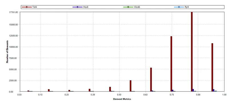
We have some elements with quality less than 10%
Setup:
After meshing, the model is set up for conditions under which it will simulate and provide results as to how the cooling system will have its effect on the graphics card.
General: Steady state pressure based solver
Model: Viscous-K epsilon with Energy equation
Material: Fluid-air
Solid-Steel, copper,silicon
Cell zone condition: Enclosure-air
Fins-copper
Processor-silicon
Base-steel
Inlet:
Type: Velocity Inlet
Velocity: 1m/s
Temperature: 300 K
Outlet:
Type: Pressure Outlet
Pressure: 0 Pa(Gauge Pressure)
Temperature: 300 K
Symmetry: Symmetry
Wall: Wall
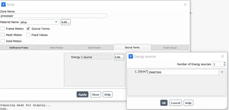
The processor is assumed as only source of heat. The heat generated by the processor is calculated as:
Graphics Card Power = 1.9W
Volume of the card = 8 x 8 x 1
= 64mm3=64e-9m3=64e^(-9)m3
Heat Generated = P/V=1.9/(64e−9)
= 29687500W/m3
Case 1:
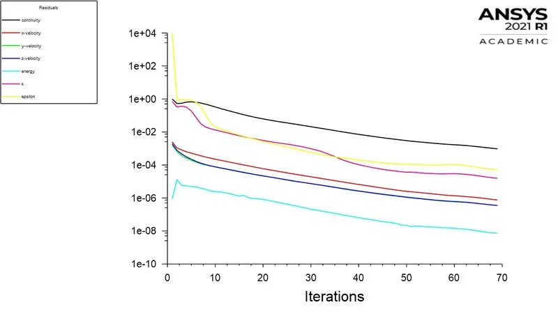
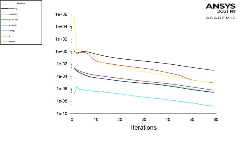
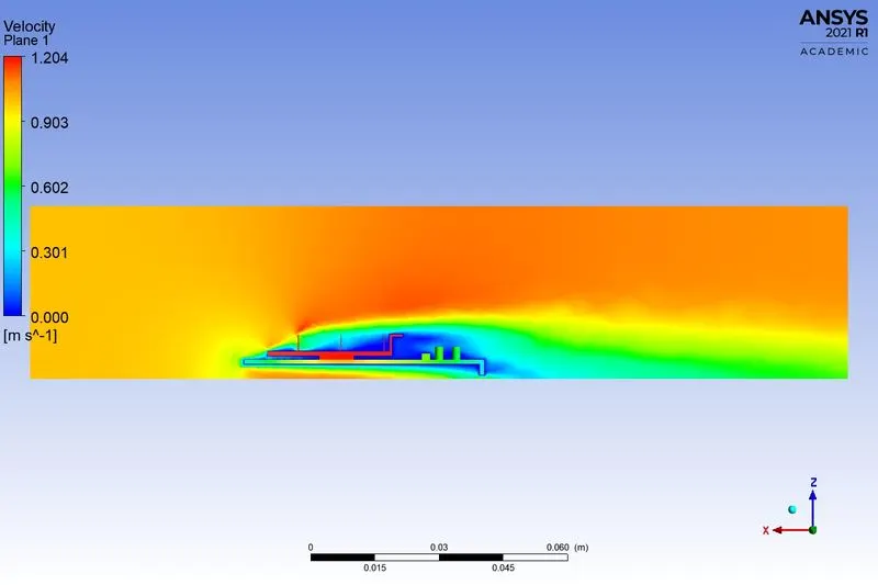
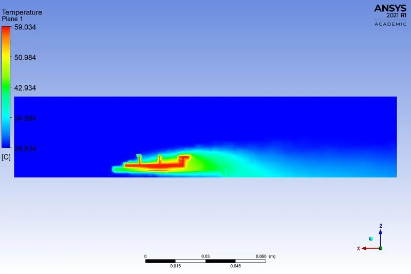
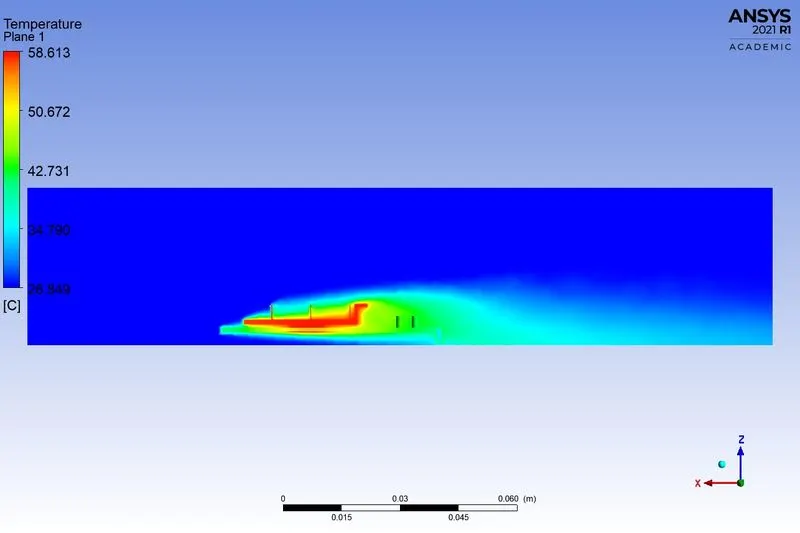
Comparing Case with Coarse and refined mesh with for velocity of 1m/s
Coarse Refined
Residuals:
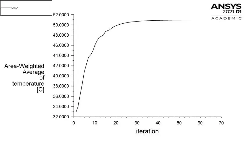
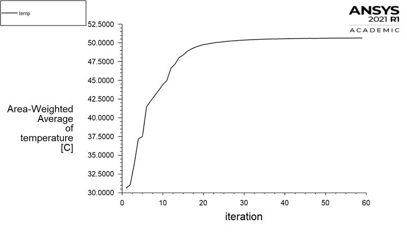
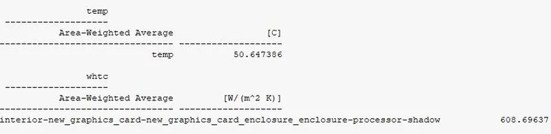
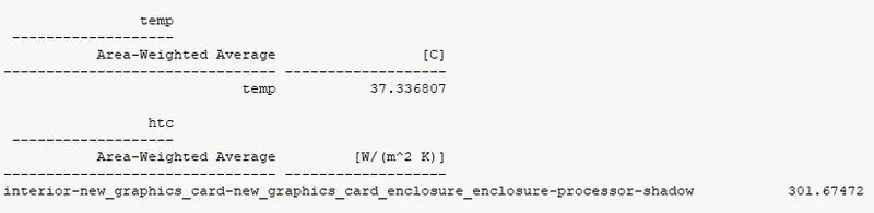
Area-Weighted average temperature
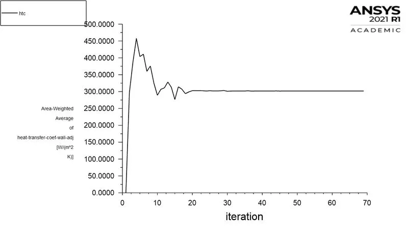
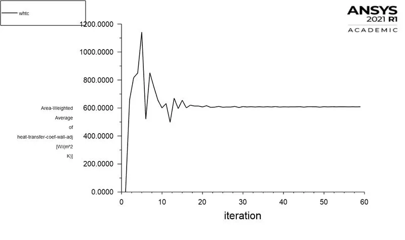
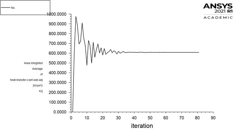
Wall heat transfer coefficient

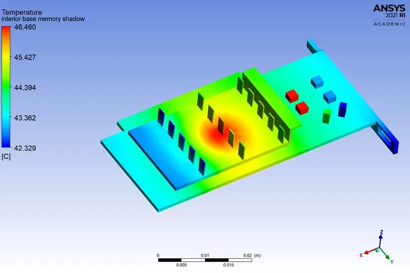
Local hotspot on model
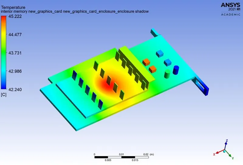
Global hotspot region
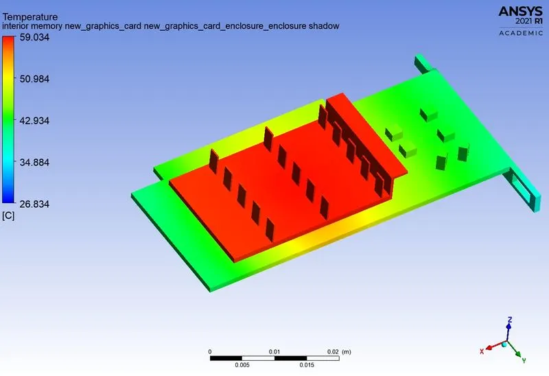
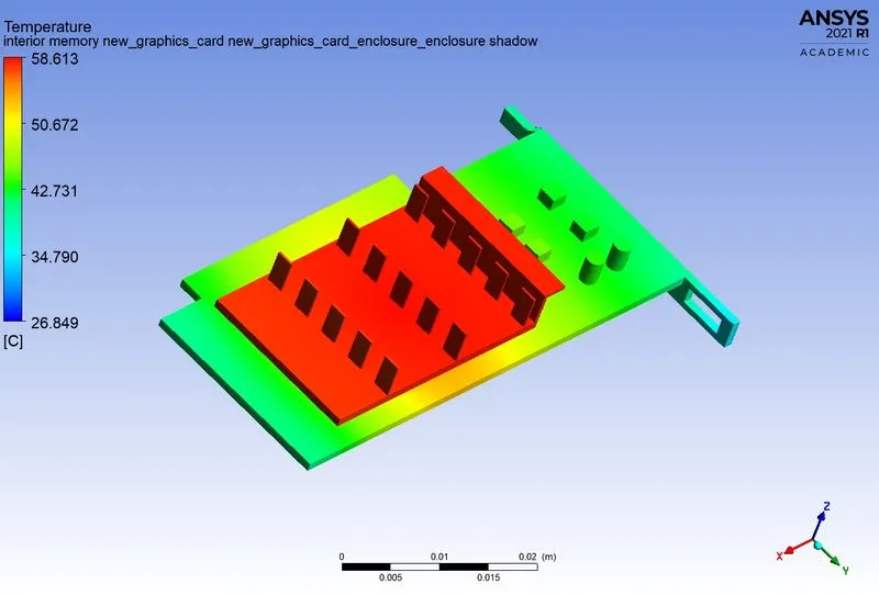
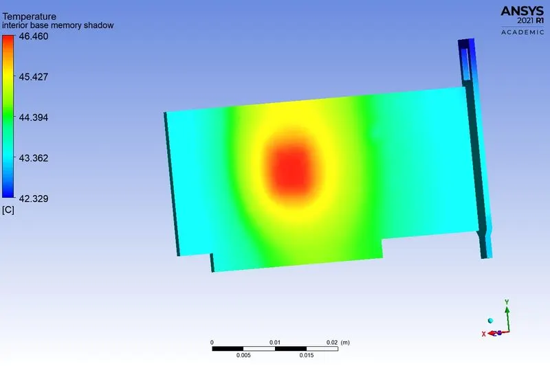
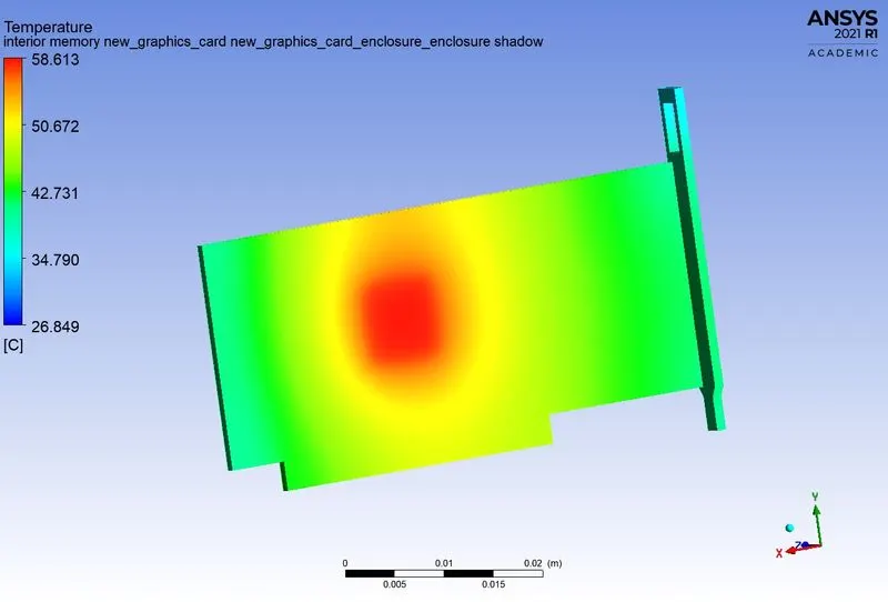
Back view of the model
Fins
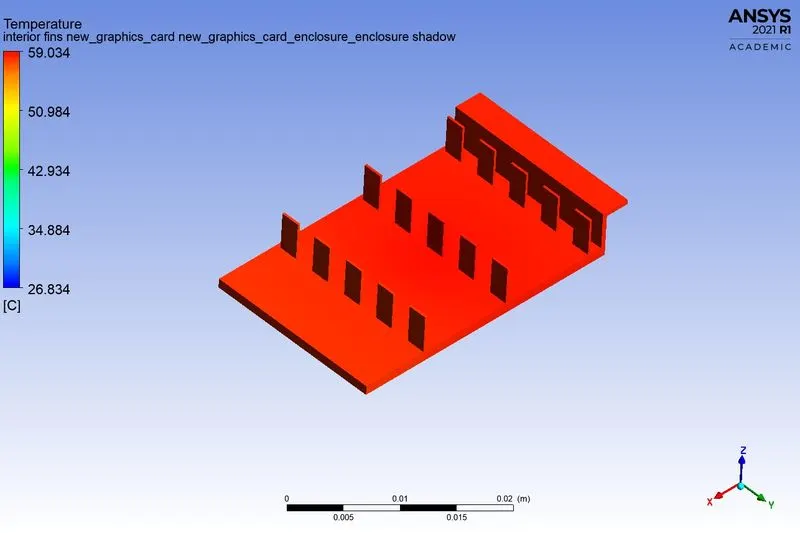
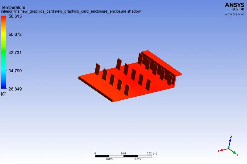
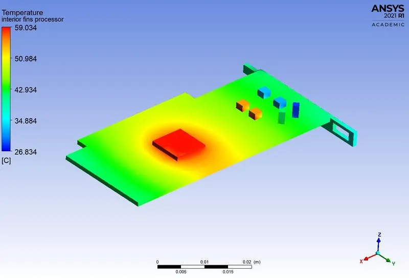
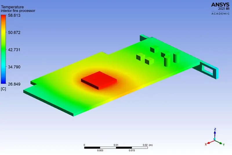
Hotspot around the processor
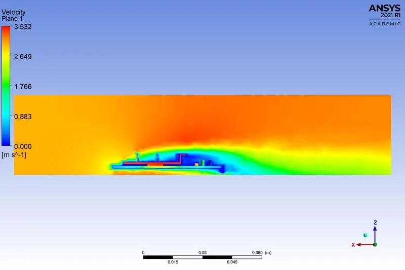
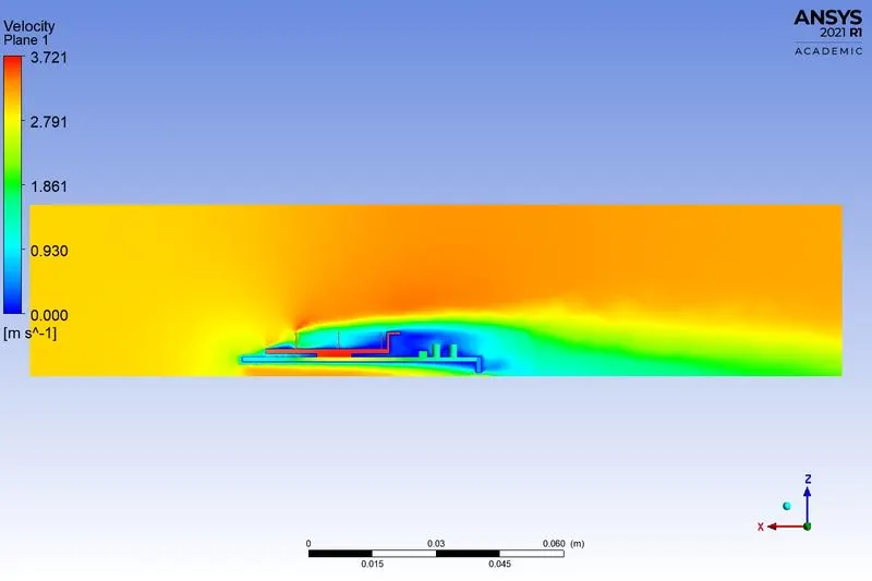
Velocity contour
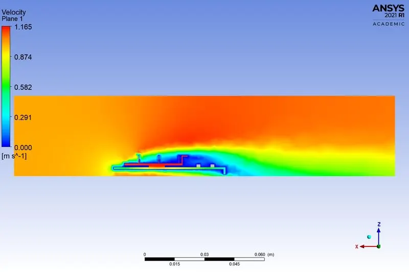
Temperature contour
Case 2:
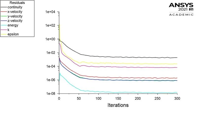
Comparing Case with Coarse and refined mesh with for velocity of 3m/s
Coarse Refined
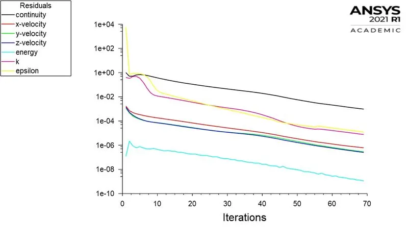
Residuals:
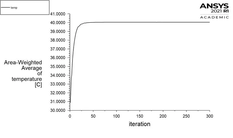
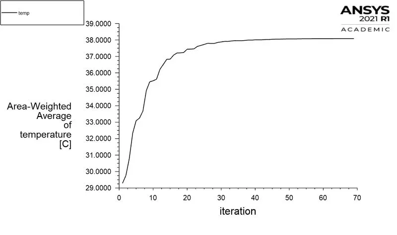
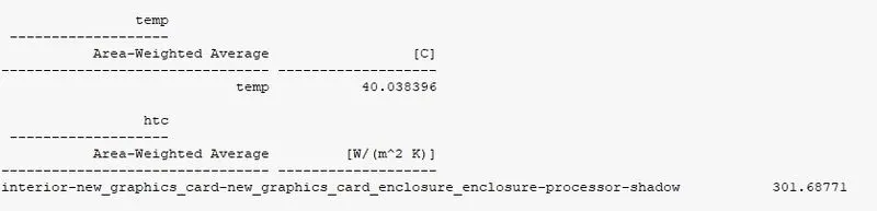
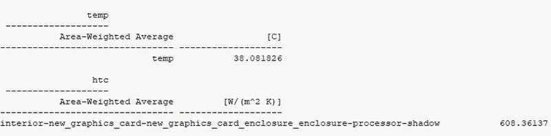
Area-Weighted average temperature
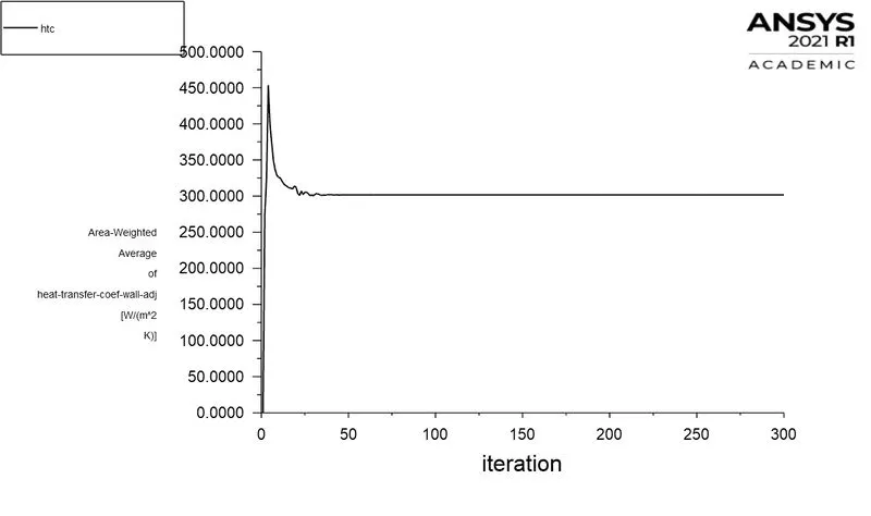
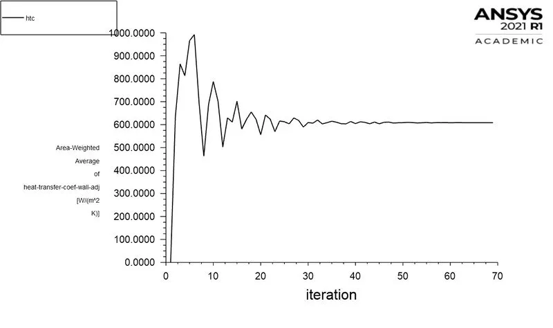
Wall heat transfer coefficient
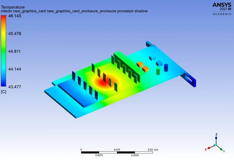
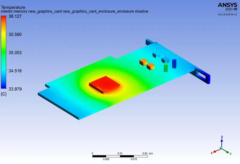
Local hotspot on model
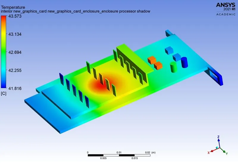
Global hotspot region
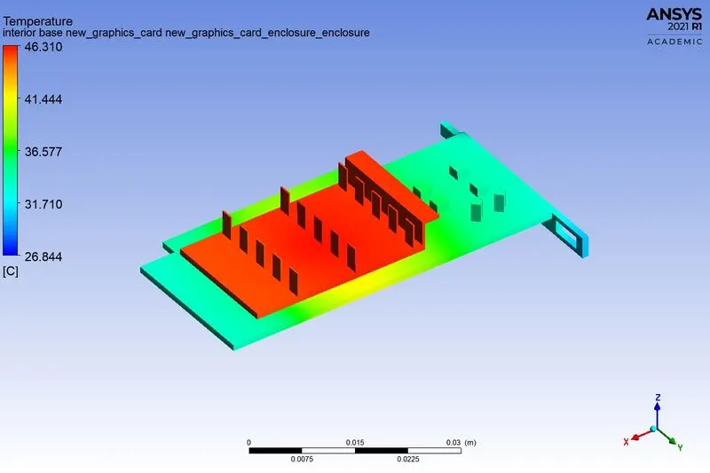
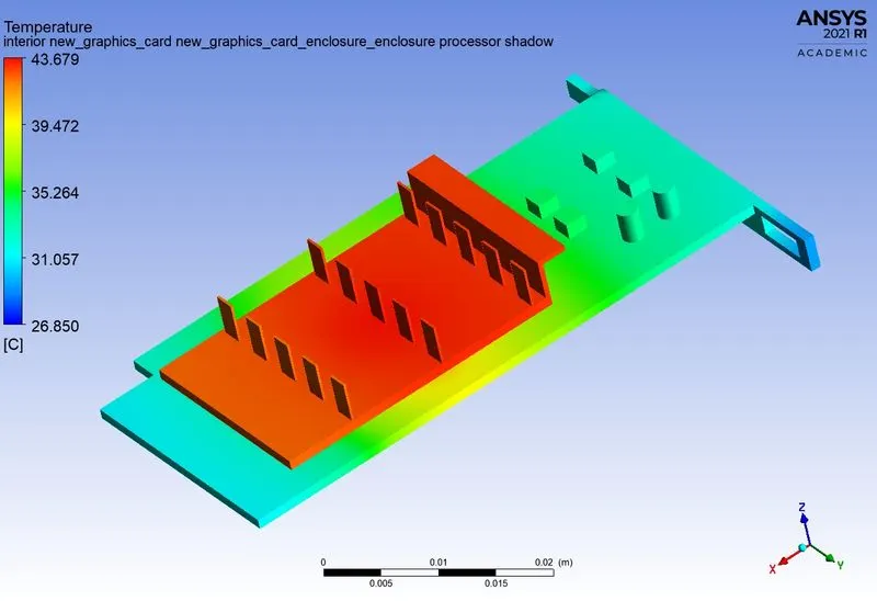
Back view of the model
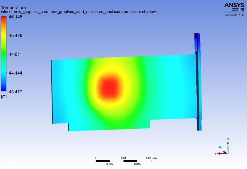
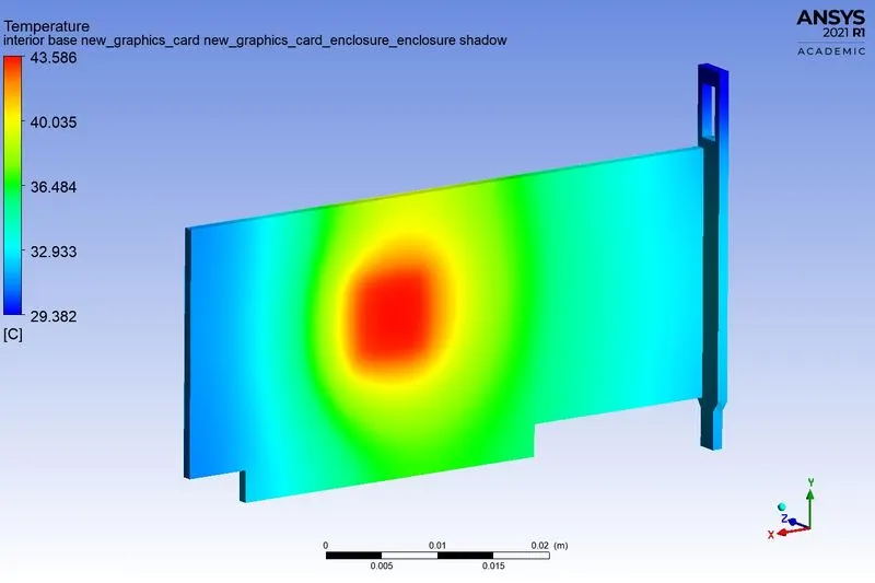
Fins
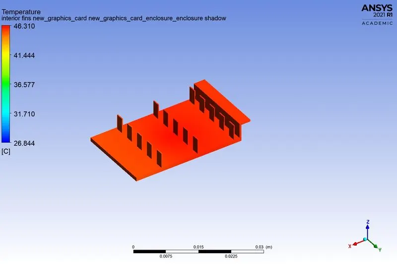
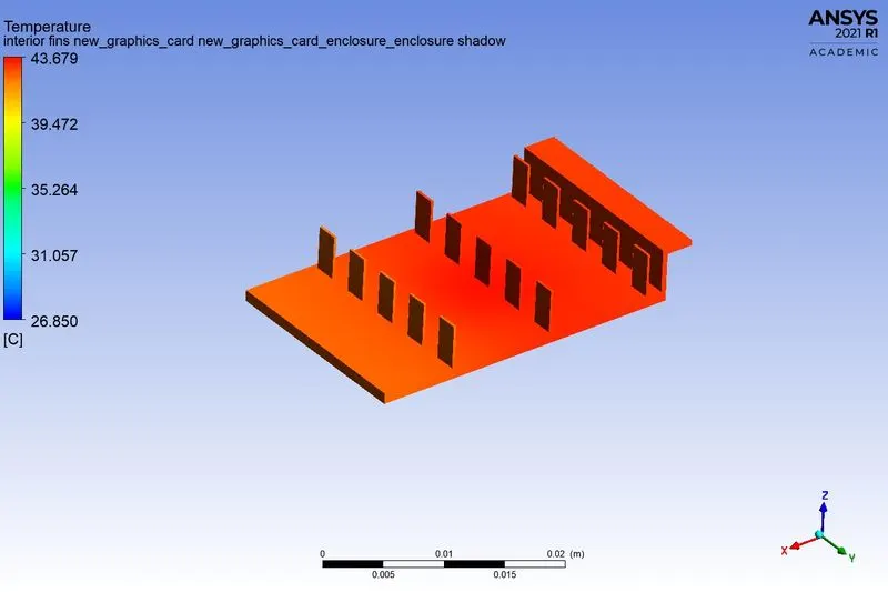
Hotspot around the processor
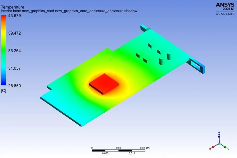
Velocity contour
Case 3:
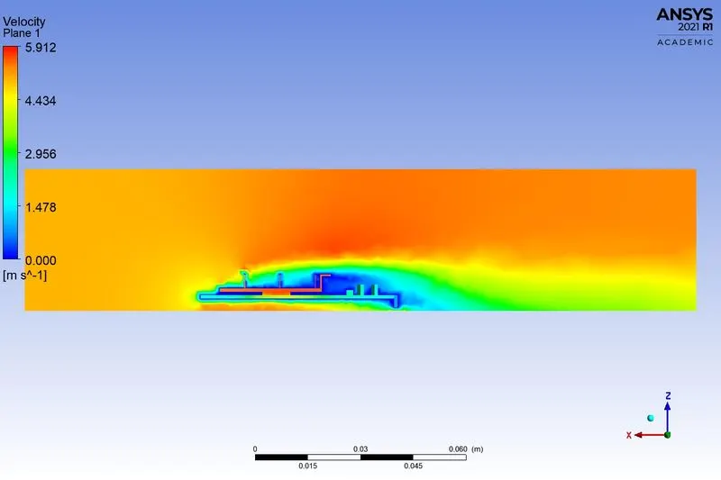
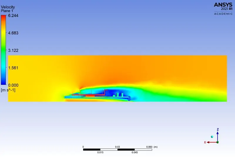
Comparing Case with Coarse and refined mesh with for velocity of 5m/s
Coarse Refined
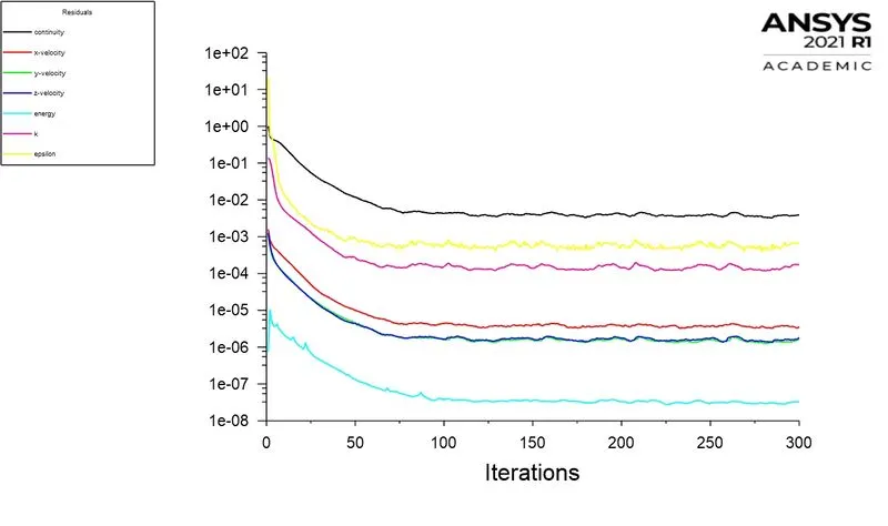
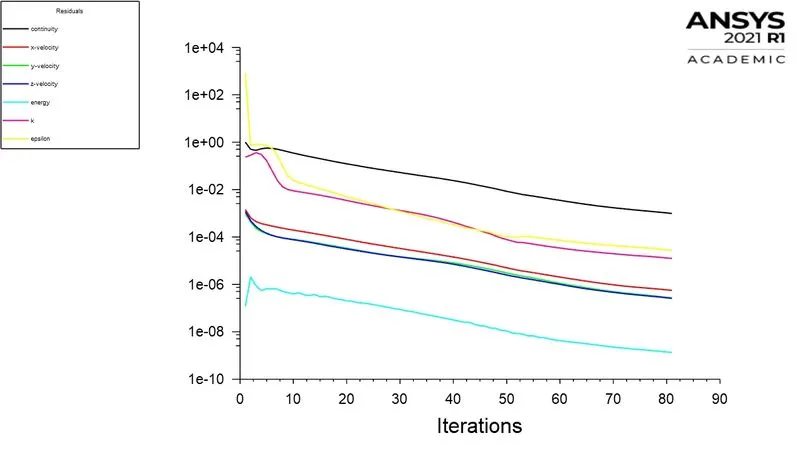
Residuals:
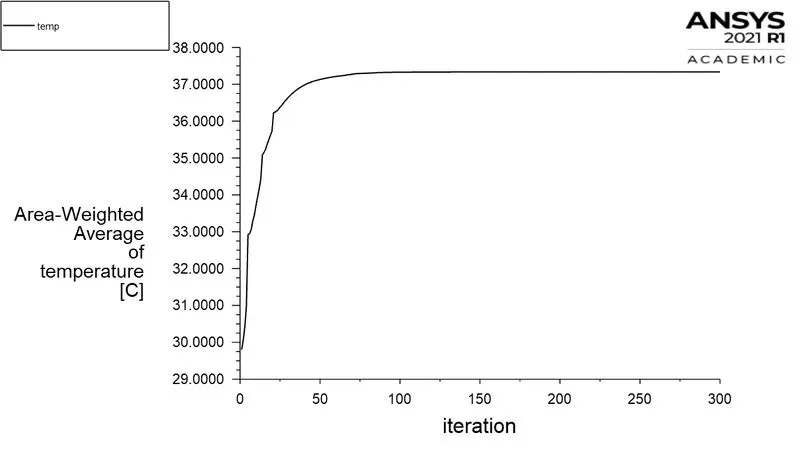
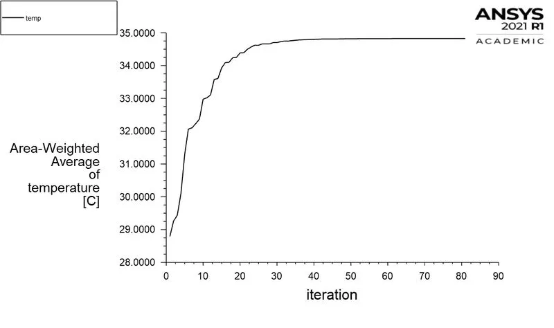
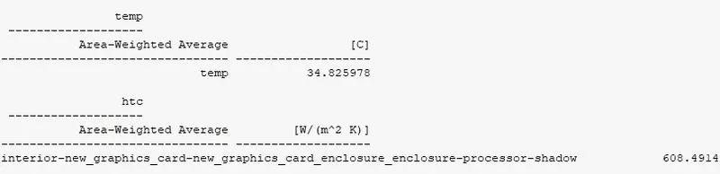
Area-Weighted average temperature
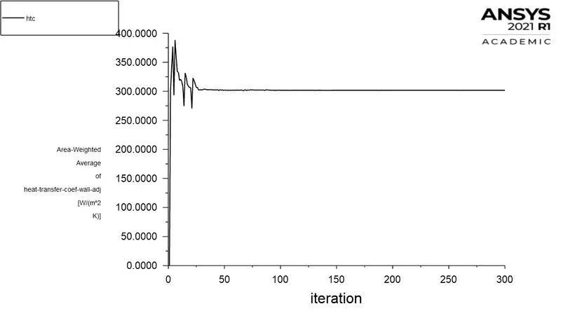
Wall heat transfer coefficient
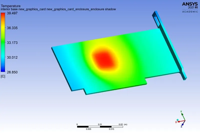
Local hotspot on model
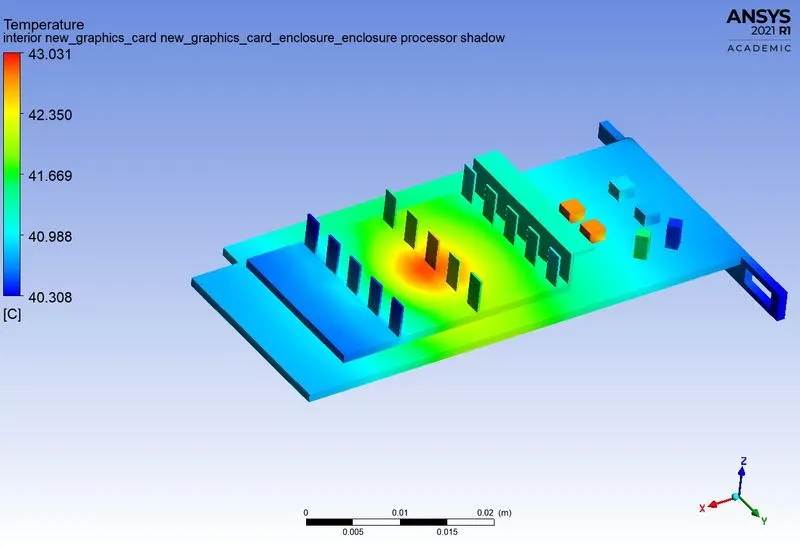
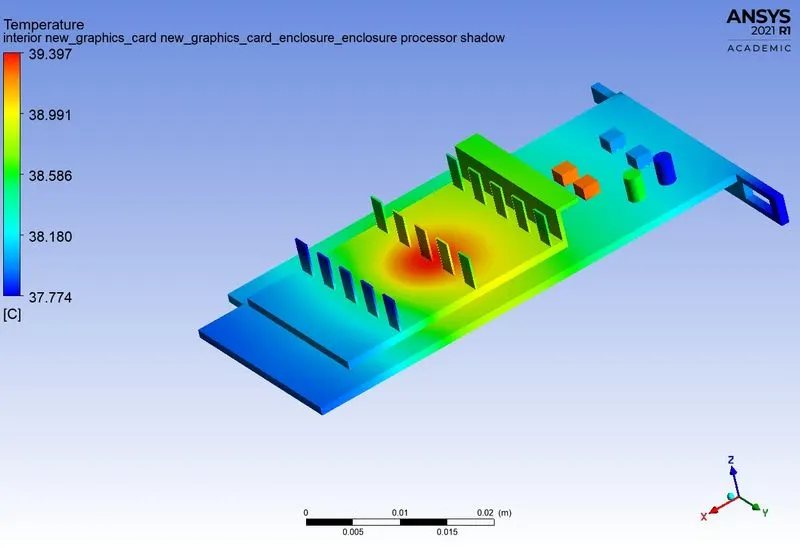
Global hotspot region
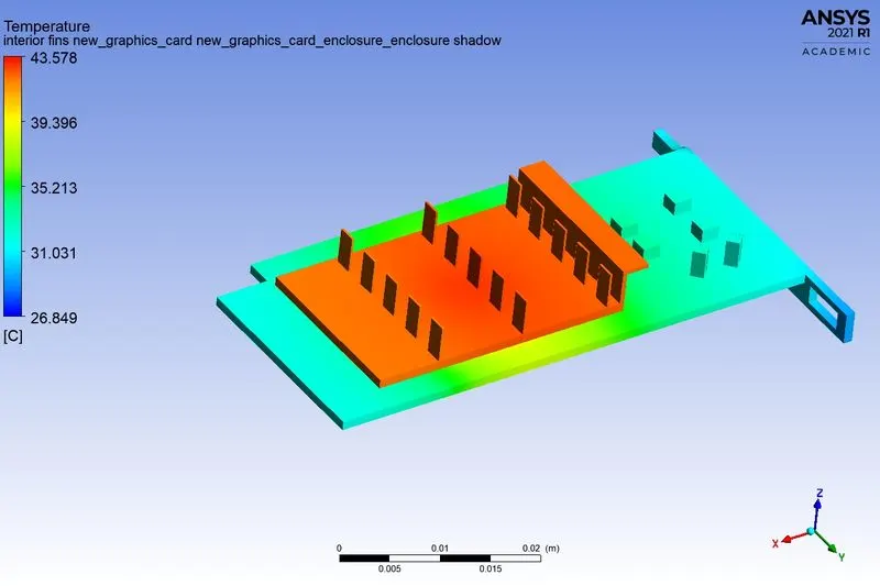
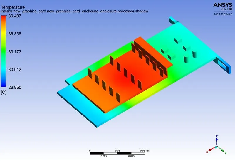
Back view of the model
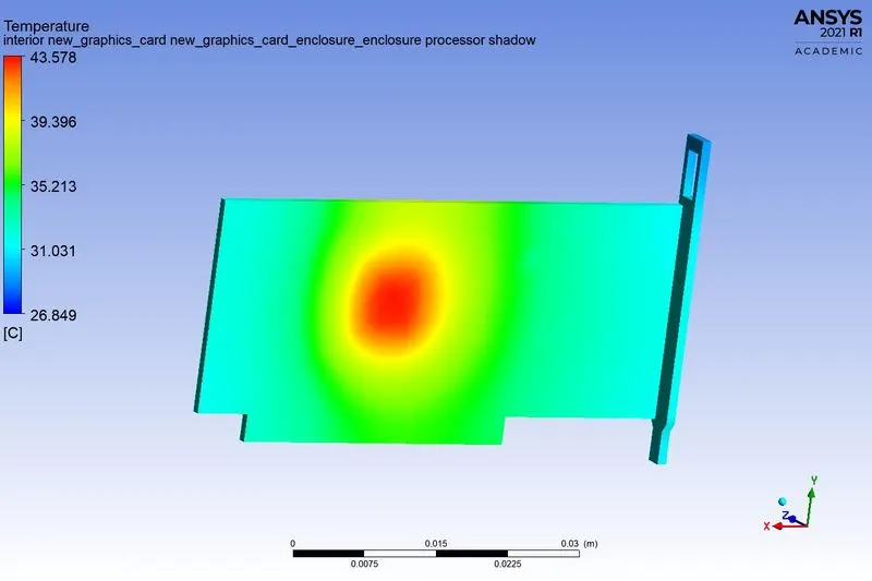
Fins
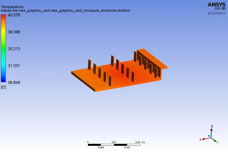
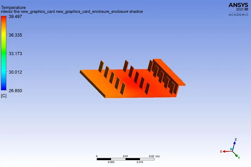
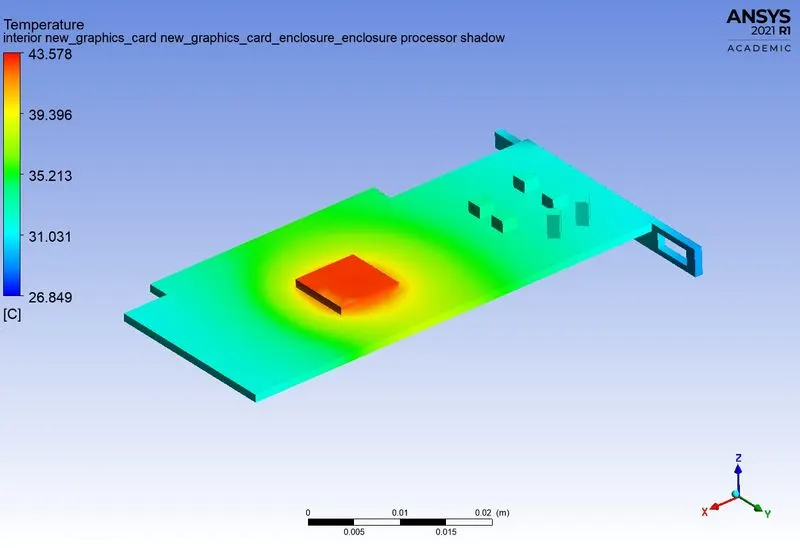
Hotspot around the processor

Velocity contour
TABULATIONS:
The results of the above cases are tabulated below
|
Coarse |
Max Temp (C) |
HTC W/(m2K) |
|
1m/s |
59.64 |
301.68 |
|
3m/s |
46.34 |
301.68 |
|
5m/s |
43.26 |
301.67 |
|
Refined |
Max Temp(C) |
HTC W/(m2K) |
|
1m/s |
58.16 |
608.69 |
|
3m/s |
43.24 |
608.36 |
|
5m/s |
39.12 |
608.49 |
Observations:
The heat transfer rate is directly affected by velocity. As we increase the velocity the Total temperature on the graphic card reduces. Meshing the geomety plays a important role to capture the heat transfer in the complex geometry.
Processor, which is the heat source is the potential hot spot of graphic card, because its the only component which consumes power. Fins play a major role in the transfer of heat.
CONCLUSION:
- As the number of elements increases the accurate results of temperature distribution is obtained
- From the above table it is fairly notable that, the net temperature of componenets of graphics card decreases with increase in inlet velocity.
- Hence it can be inferred that a higher inlet velocity results in better cooling and lower the average temperature thus keeping the components safe from damage.
- Furthermore, it can be observed that the temperature of components increases as the inlet velocity decreases from 5 m/s to 1m/s, also proving that higher velocity results in better cooling.