Week 6 - CHT Analysis on a Graphics card
Aim: - To perform Steady State Conjugate Heat Transfer Simulation on a Model of Graphic Card.
Objective: -
- To find Maximum temperature and heat transfer coefficient attained by the model.
- To run the simulation for inlet velocity of 1 m/s, 3 m/s and 5 m/s.
- To validate the simulation and identify potential hotspot on the model.
Theory: -
Conjugate Heat Transfer (CHT) –
Conjugate heat transfer (CHT) analysis can accurately predict heat transfer by simultaneous solving all the relevant solid and flow field heat transfer processes.
It allows for the simulation of heat transfer between solid and fluid domains by exchanging thermal energy at the interfaces between them, which is more stable and provides faster convergence as the energy equation is strongly coupled between the solid and fluid regions.
Used in Thermal analysis of –
- Systems – HVAC, Automotive etc
- Electronic Devices for Heat Dissipation analysis
- Mechanical Components – Turbochargers, Combustor, Burners etc.
- Power Plants.
A graphics card also called video card generates feed of output images to display. IN doing so it generates heat by consuming electrical energy. To ensure efficient functioning the generated heat is dissipated using various techniques such as cooling fans, heat sink/fins incorporated in design colling gel etc.
In this project CHT analysis is done on the graphics card model with fins providing convective heat transfer to surrounding where free stream velocity is maintained by cooling fans of by other means.
Case Setup
Geometry –
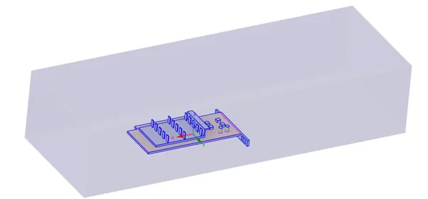
It consists of an encloser enclosing 3 parts that are –
- Fins
- processor
- Base and components
Material considered for different parts
- Fins – Copper
density = 8978 kg/m3 heat capacity= 381 J/kg-K Thermal Conductivity= 387.6 W/m-K
- Processor & Components – Silicon
density = 2000 kg/m3 heat capacity= 710 J/kg-K Thermal Conductivity= 150 W/m-K
- Base – FR4 (glass-reinforced epoxy laminate material)
density = 1850 kg/m3 heat capacity= 950 J/kg-K Thermal Conductivity= 0.29 W/m-K
- Encloser – Fluid domain (air)
density = 1.225 kg/m3 heat capacity= 1006.43 J/kg-K Thermal Conductivity= 0.0242 W/m-K
Viscosity = 1.7894e-5 kg/m-s
Meshing –
Two types of mesh are used one being Baseline mesh and other being Refined mesh.
Baseline Mesh –
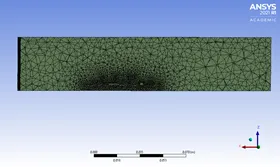
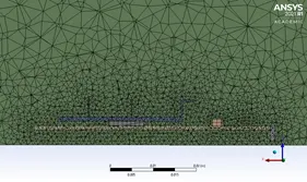
No. of elements – 239430 Global element size = 5 mm (max up to 8 mm)
Capture proximity and curvature on with min size 1 mm.
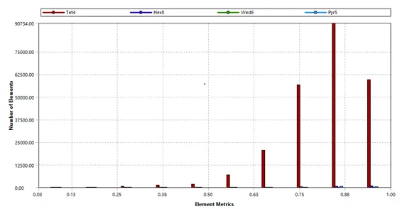
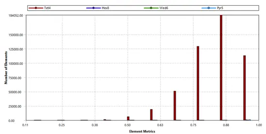
Quality of mesh –
Refined Mesh –
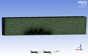
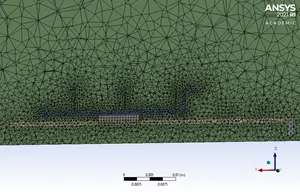
No. of elements – 503921 Global element size = 3 mm (max up to 4 mm)
Fin body sizing – Element size = 0.5 mm
Base and components Body sizing = 0.8 mm
Capture proximity and curvature on with min size 0.8 mm.
Quality of mesh –
Fluent setup –
- steady state solver
- pressure based
- K-ɛ Turbulence model with scalable wall function
Heat generation –
It is assumed that processor produces 5 W energy and volume of processor are 64 mm3
hence source term is 7.8125e7.
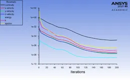
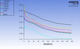
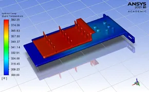
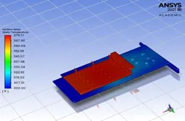
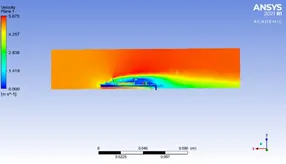
case 1. Inlet velocity 5 with baseline mesh and Refined Mesh
|
|
Baseline |
Refined |
|
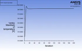
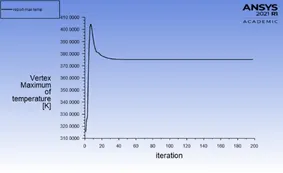
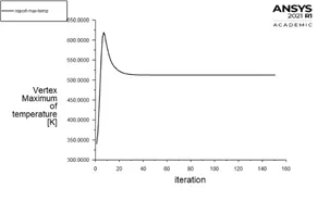
Residual plot |
 |
 |
|
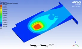
Global Temp. contour |
 |
 |
|
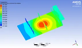
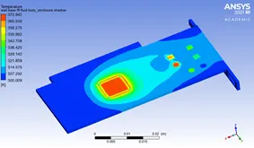
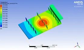
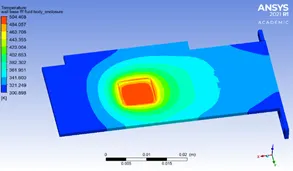
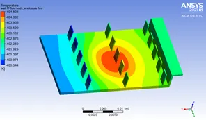
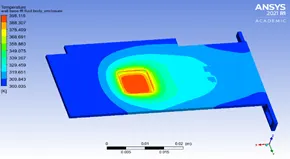
Local Temp. contour |
Fin Base |
Fin Base
|
|
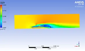
Velocity in mid plane |
 |
 |
|
Max. Temp. |
Max temp. = 382.2894 K |
Max temp. = 375.1123 K |
|
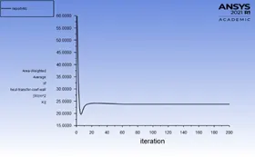
heat transfer coefficient |
HTC = 23.74641 W/m2-K |
HTC = 24.99761 W/m2-K |
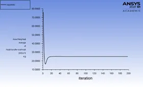
Case 2. For inlet velocities 1m/s and 3m/s Using Refined Mesh
|
|
1 m/s |
3 m/s |
|
Residual plot |
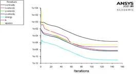 |
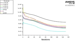 |
|
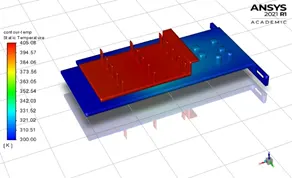
Global Temp. contour |
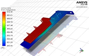 |
 |
|
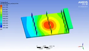
Local Temp. contour |
Fin
Base
|
Fin
Base
|
|
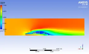
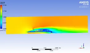
Velocity in mid plane |
 |
 |
|
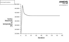
Max. Temp. |
Max Temp. = 512.459 K |
Max Temp. = 405.0808 K |
|
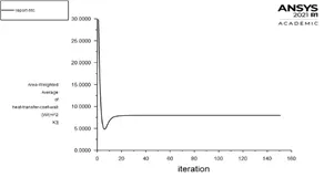
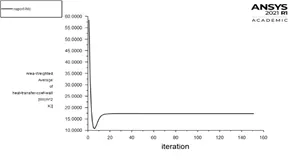
heat transfer coefficient |
HTC = 7.987 W/m2-K |
HTC = 17.35393 W/m2-K |
Results: -
For different Inlet velocity values, the following output is calculated by using Refined Mesh
|
inlet velocity (m/s) |
Maximum Temperature (K) |
average Temperature (K) |
Heat transfer coefficient (W/m2-K) |
|
5 m/s |
375.1123 |
333.2425 |
24.9976 |
|
3m/s |
405.0808 |
348.0003 |
17.35393 |
|
1m/s |
512.459 |
403.5084 |
7.987001 |
Conclusion: -
- As the inlet velocity increases the Heat transfer coefficient Increases, providing better cooling.
- Low inlet Velocities should be avoided as heat could reach to neighboring components as could be seen in the Base Local contour. Either base material should be upgraded or Heat generations should be kept lower than 5 W.
- The Spots in contact with processor has the highest temperature, which can be further reduced by placing more closely packed fin i.e., Pin fin.