Week 6 - CHT Analysis on a Graphics card
Aim:
To perform a steady-state conjugate heat transfer study on a graphics card model.
Run the simulation to get the best mesh possible, combining baseline mesh and refined mesh in various places.
Procedure:
Conjugate heat transfer analysis:
Conjugate heat transfer analysis is based on a mathematical structural problem that represents the heat transfer between the body and the fluid moving over or inside it as a result of two-object interaction. The matching interface includes information for temperature distribution and heat flux along the interface, removing the need to calculate the heat transfer coefficient.
CHT analysis simulates heat transfer between solid and liquid domains by exchanging thermal energy at their interfaces. The modeling of heat exchangers, the cooling of electronic equipment, and general-purpose cooling and heating systems. In this project's CHT, the convection mode is used.
Geometry
- 1:Import the geometry to Spaceclaim.
- Base :
- Processor :
- FIns:
- The Share Topology feature should be turned on. From a sectional-cut view, we can confirm it.
2: Meshing
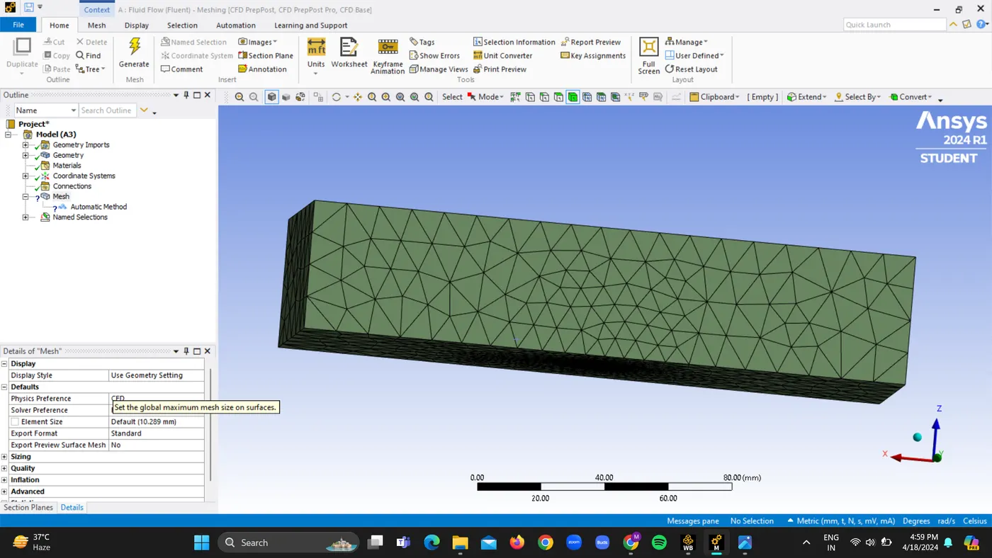
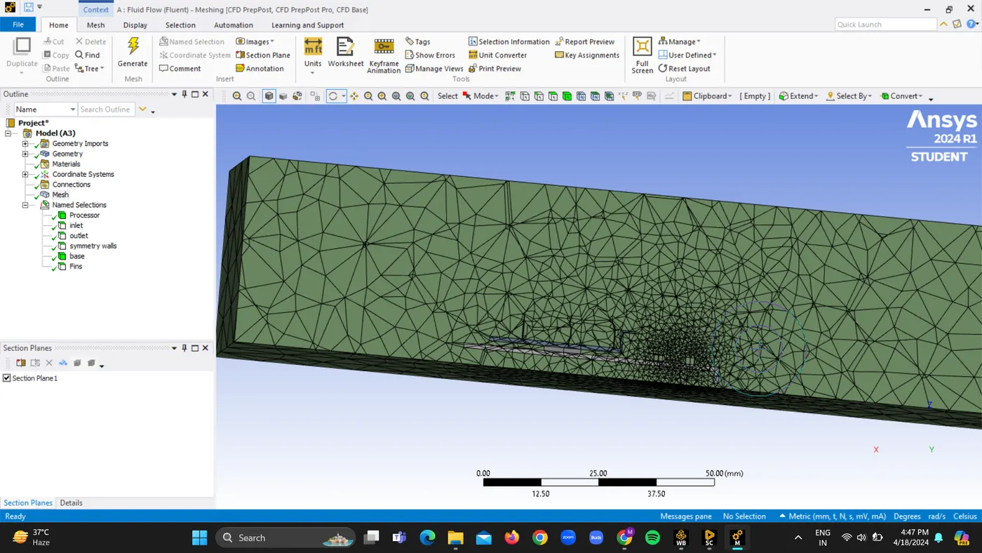
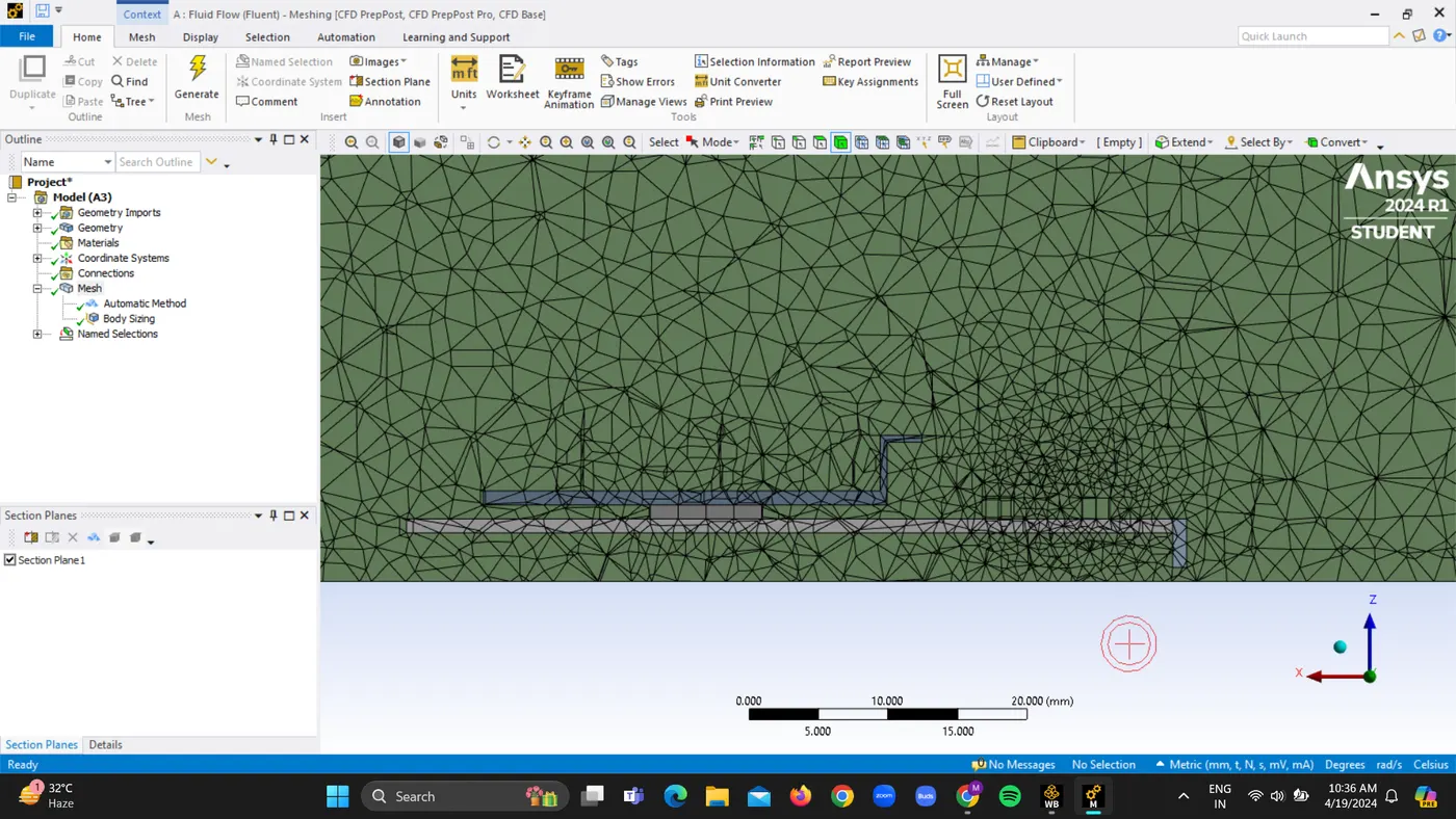
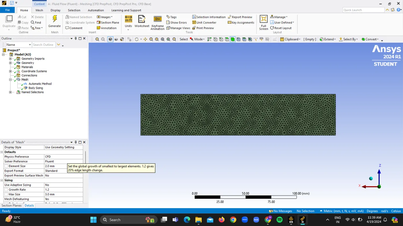
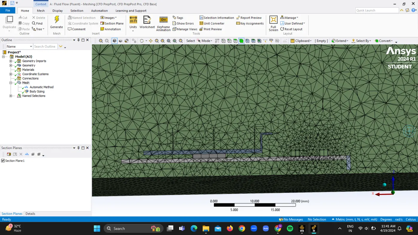
Create a baseline mesh of 10.289 mm. Also create the refined Mesh and give appropriate sizing to the processor.
3. Solving
1. Open Ansys fluent > steady state > k epsilon.
2. Energy should be on.
3. Create user-defined materials for the base to be FR4 solid zones, the fins to be aluminum, and the processor to be silicon.
4. Air is default material for fluid zone for enclosure.
a. Air:
b. Alumunium:
c. Silicon:
d. FR4
5. Give the energy source for processor from cell zones as 15625000 W/m3.
6. Define the maximum temperature and maximum heat transfer coefficient in the report, along with the proper velocity value for the inlet and temperature and velocity contours.
7. Initialize and simulate for 500 iterations.
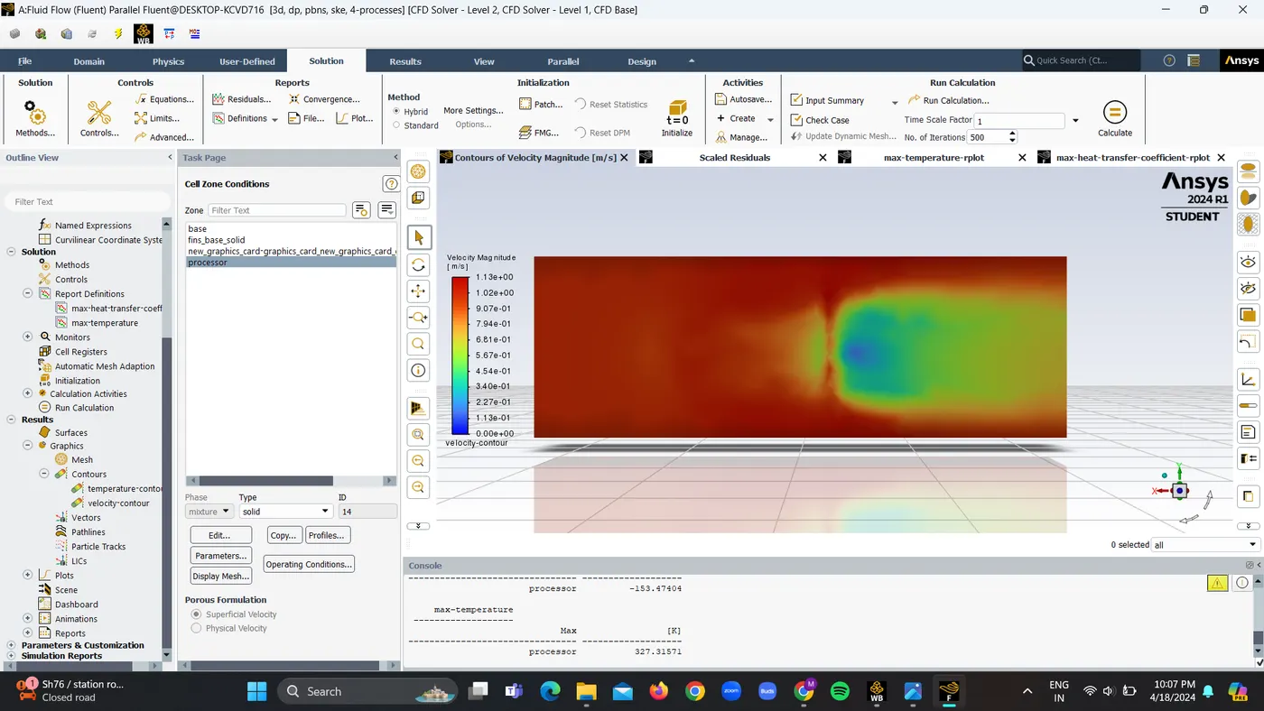
A. For Baseline Mesh of 10.289 mm and velocity given as 1 m/s
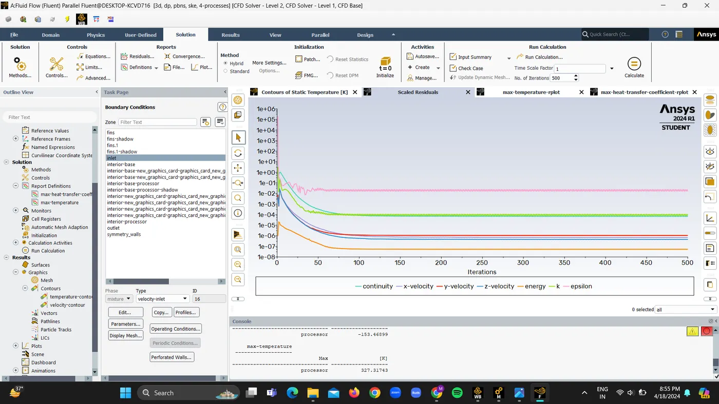
1. Residuals
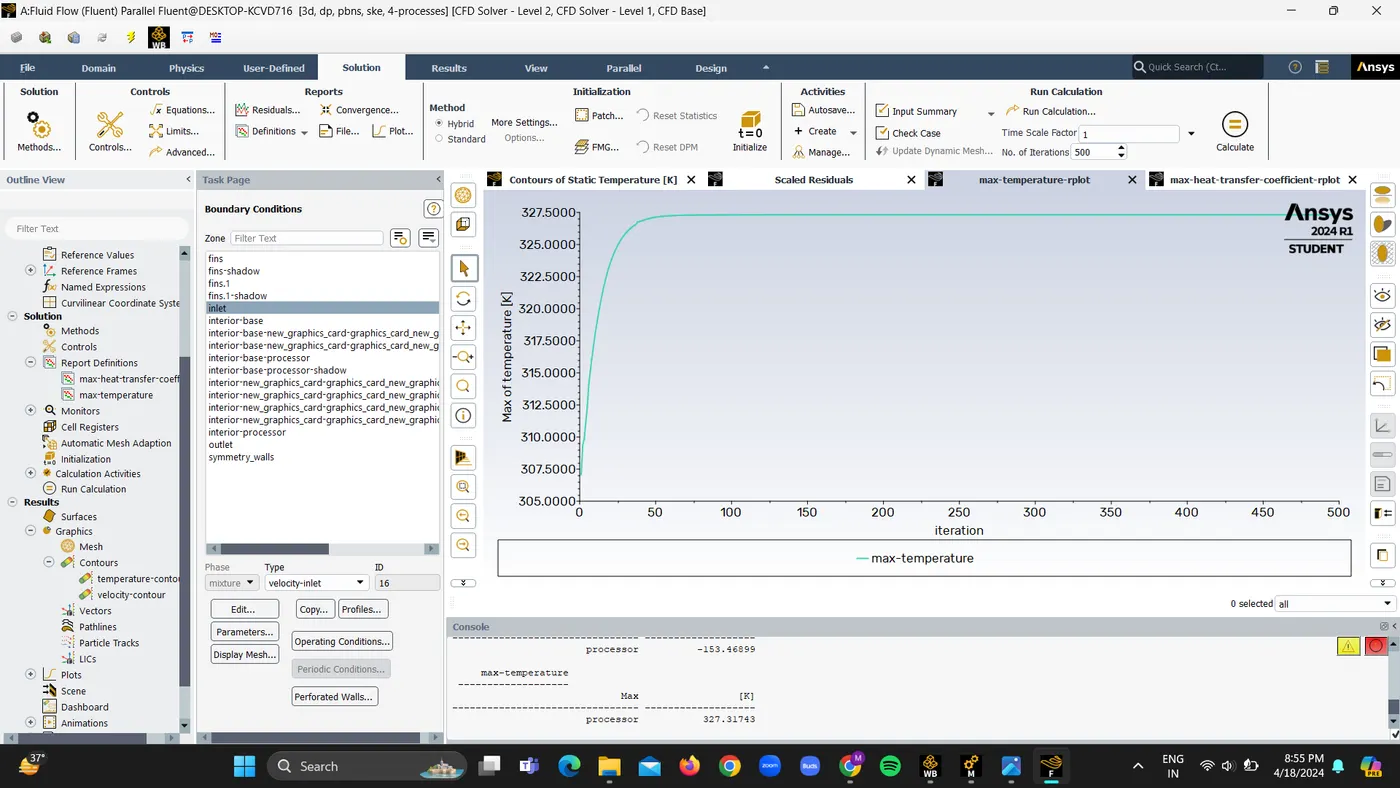
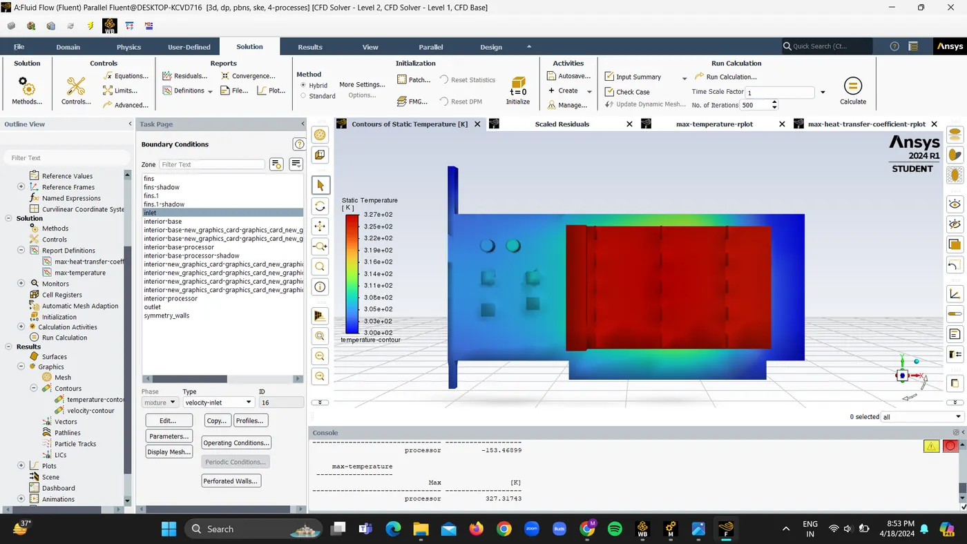
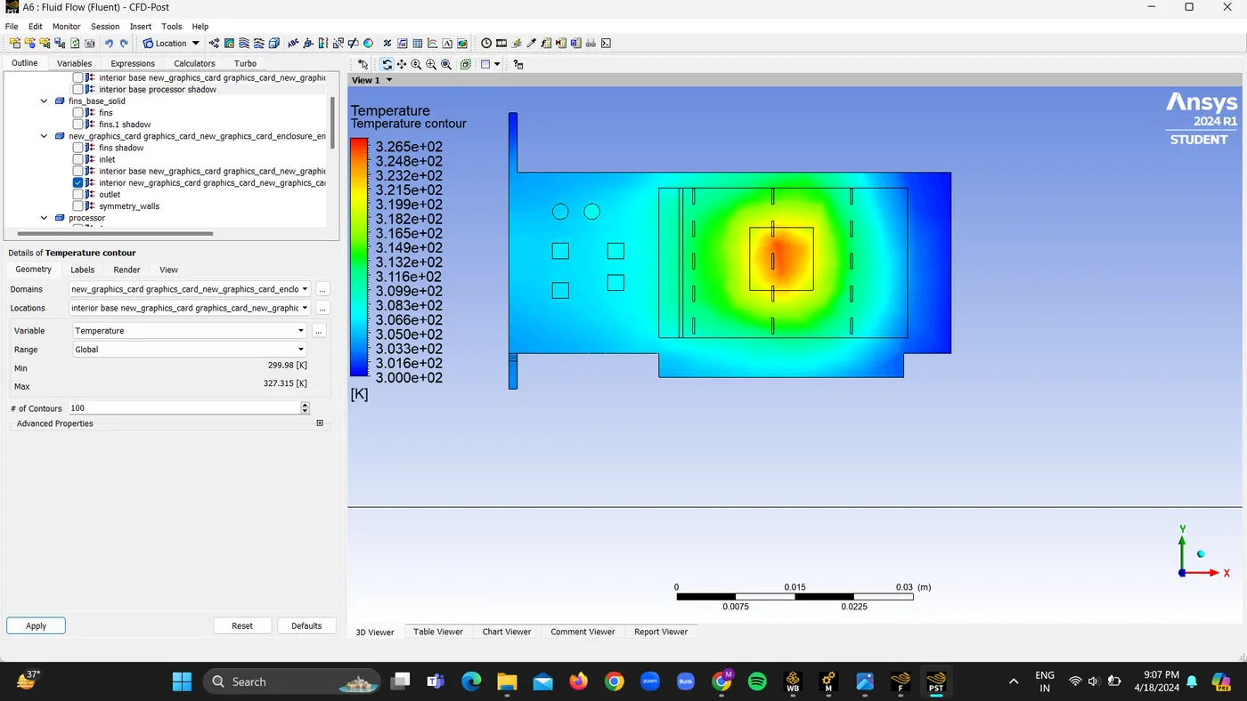
2. Maximum temperature is 327.31K
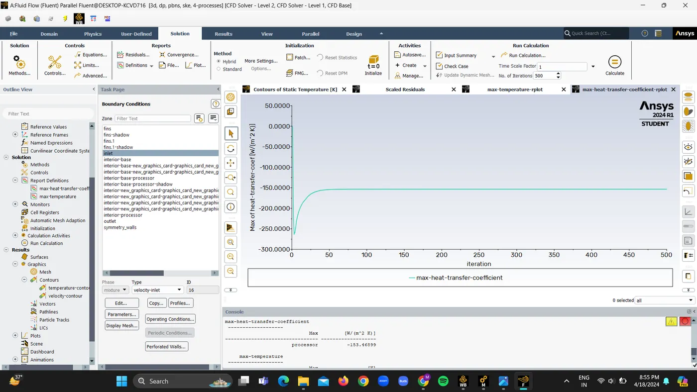
3. Maximum Heat Transfer coefficient is -153.46 W/m2K
4. Temperature contour Plot
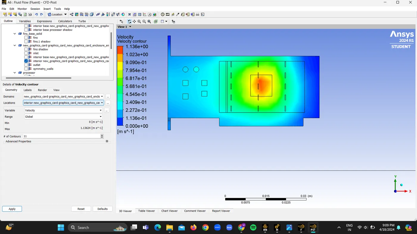
5 Velocity contour plot
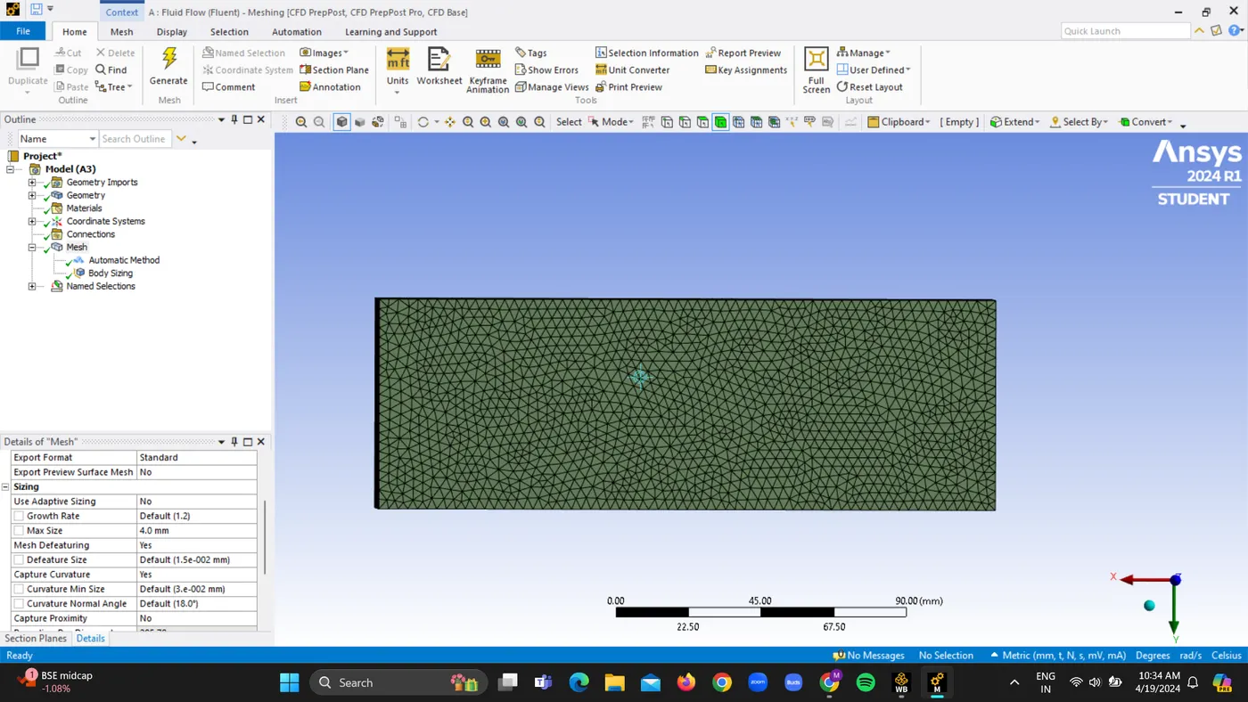
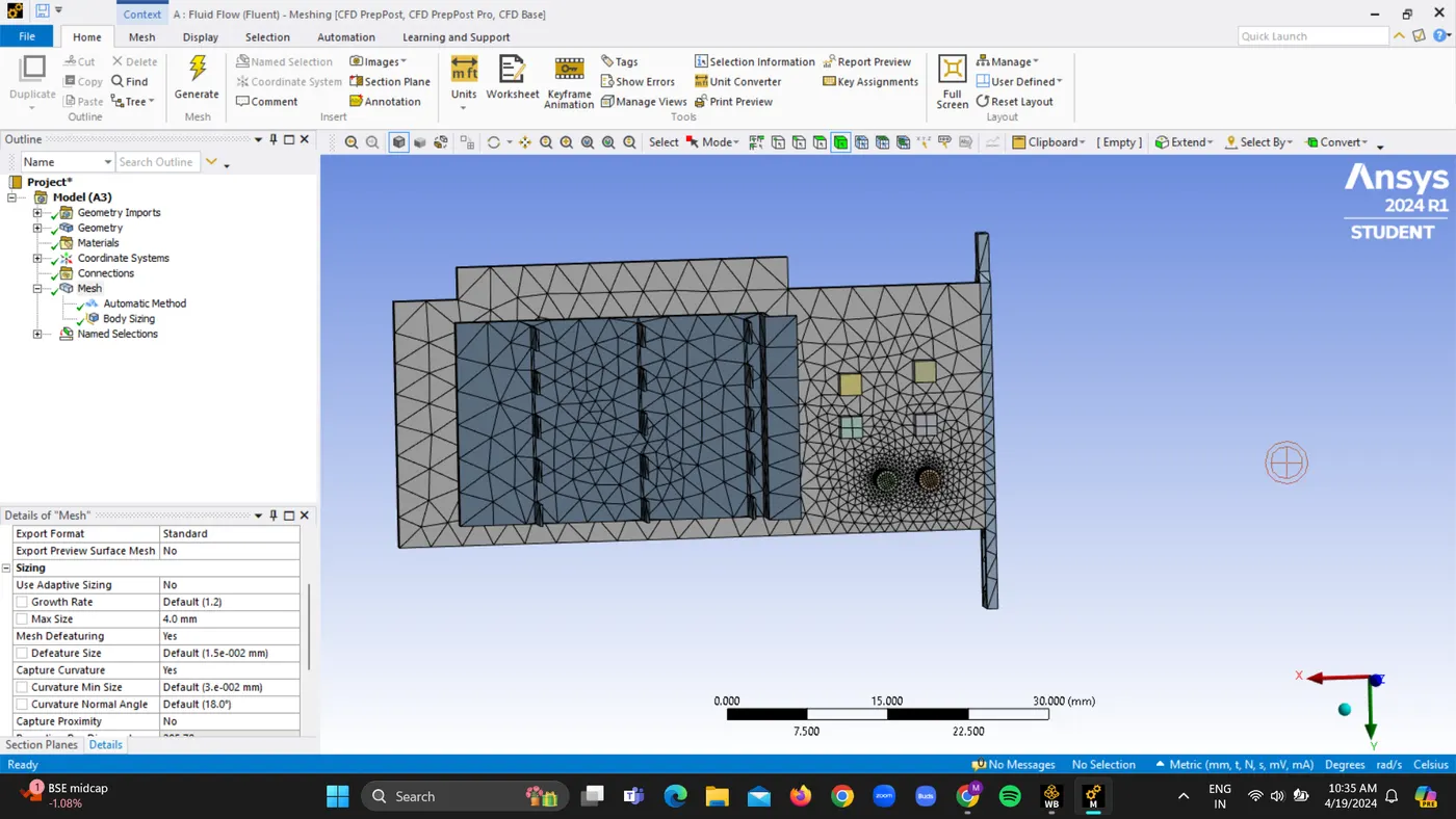
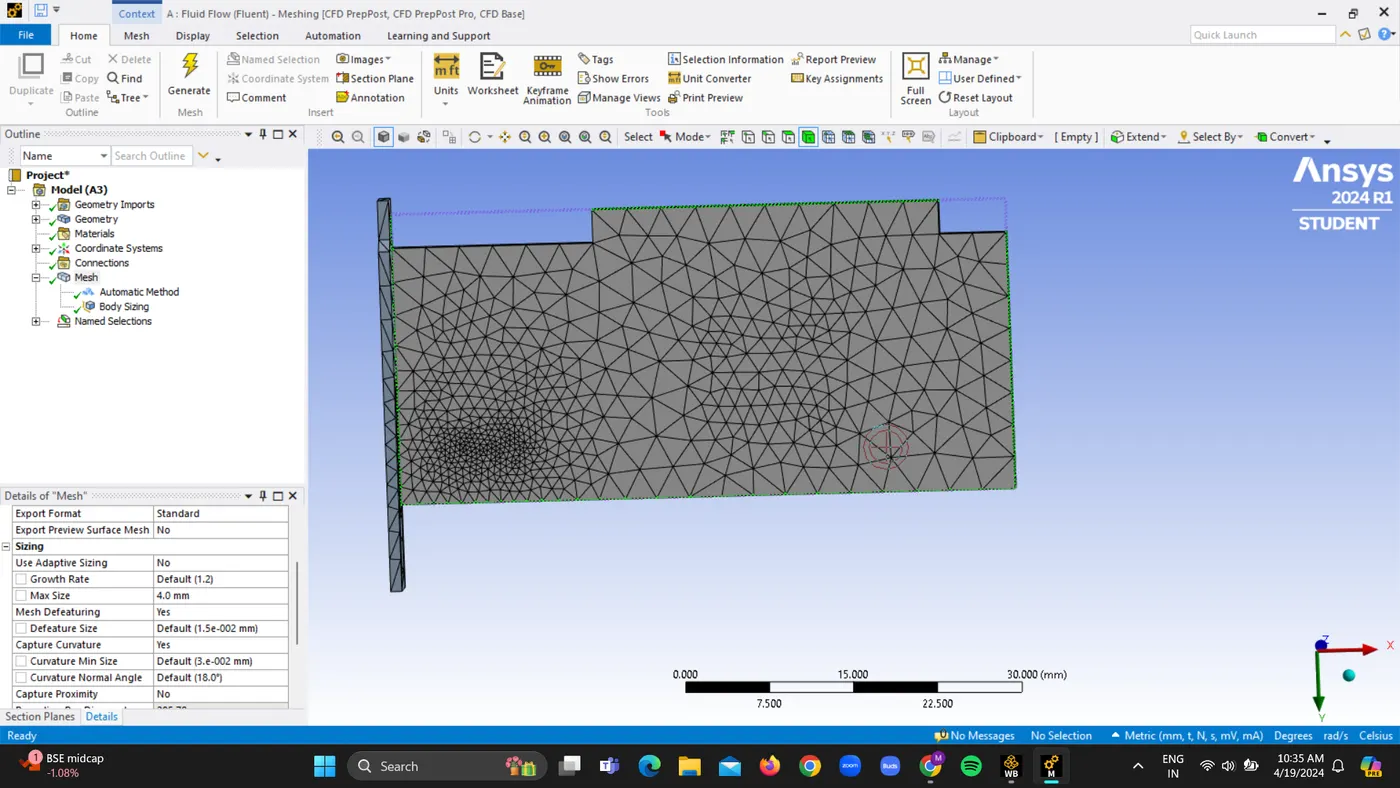
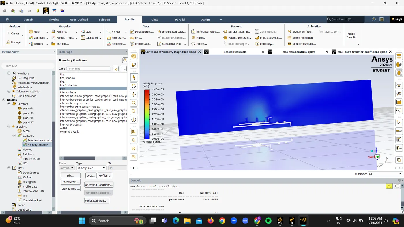
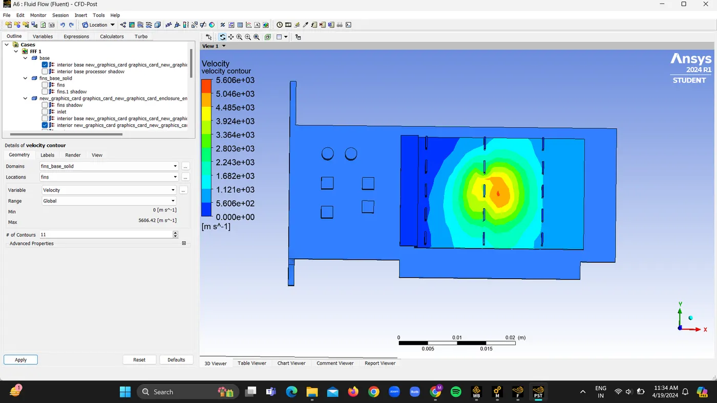
B. For Refined mesh of 3mm with body sizing given and velocity given as 3m/s
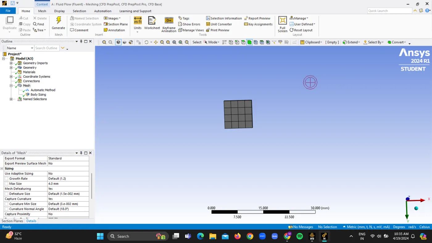
1.Meshed Geometry
2. Solving
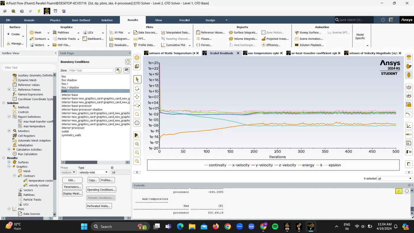
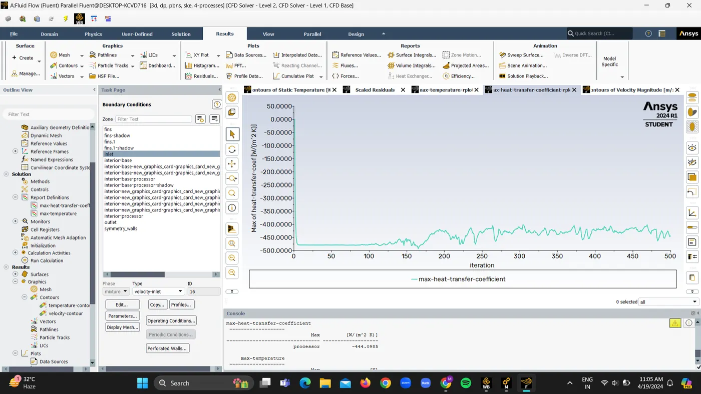
Residuals:
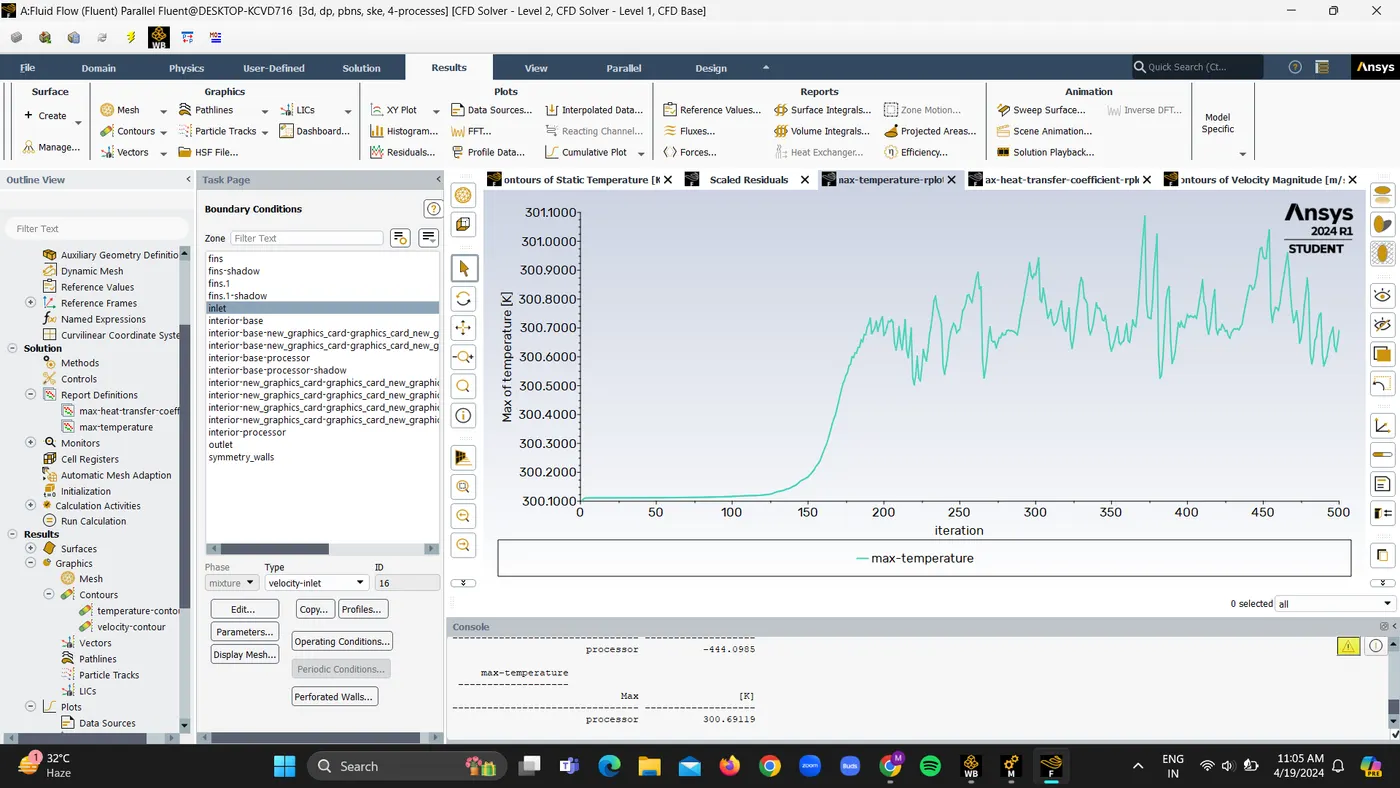
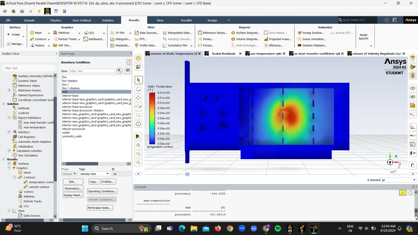
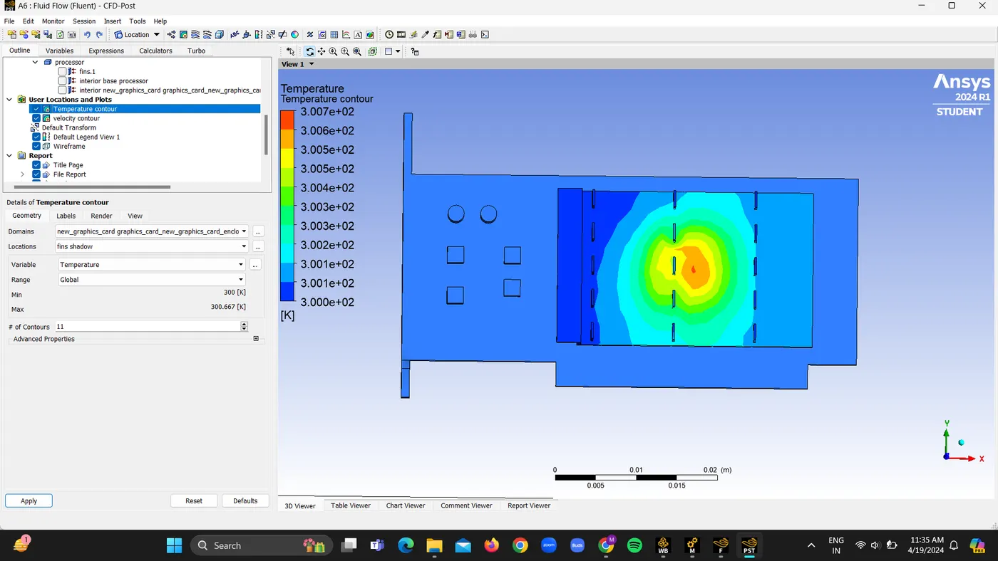
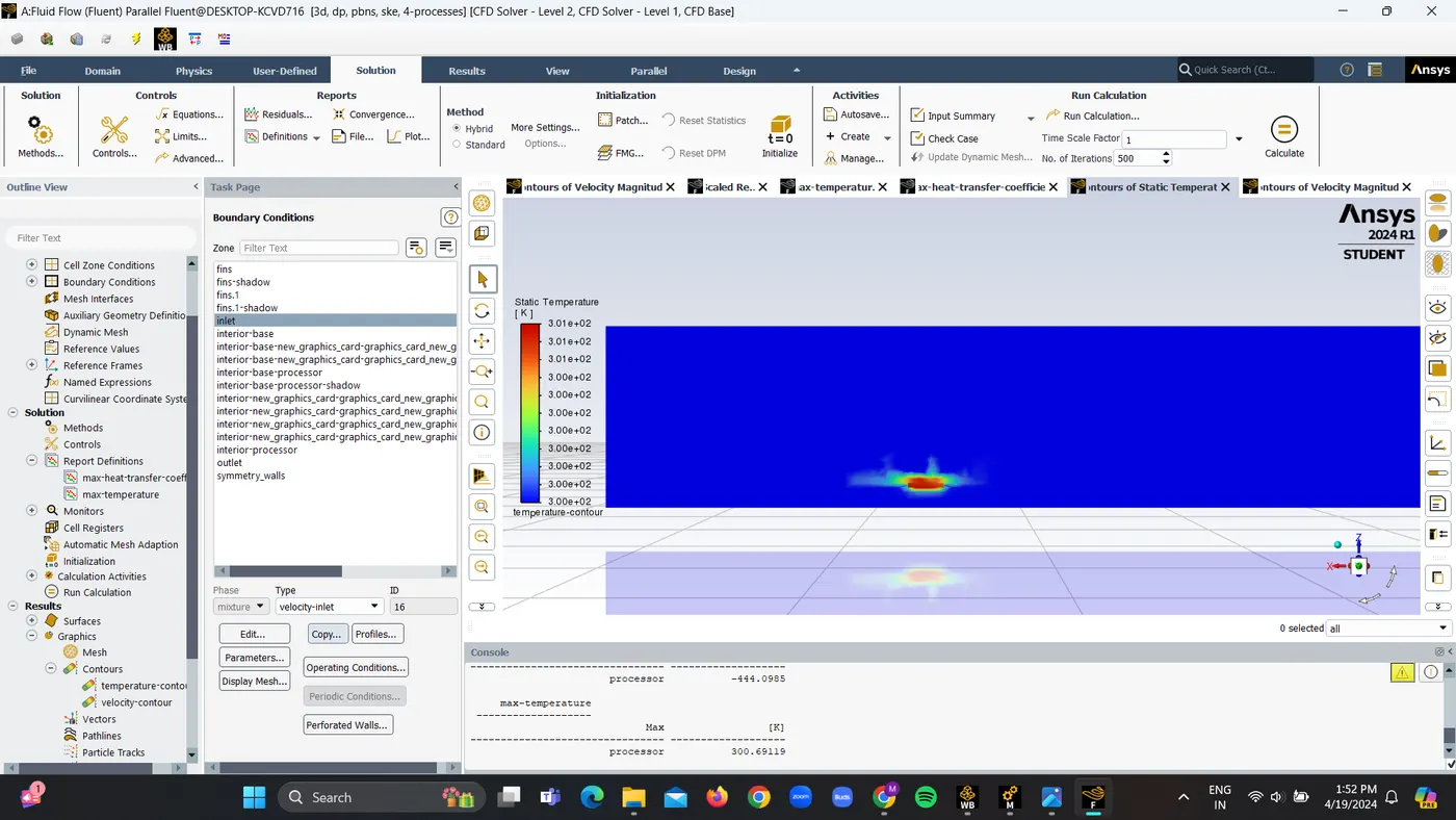
Maximum Temperature is 300.69 K
Maximum heat transfer coefficient is -444.09 W/m2K
Temperature contour
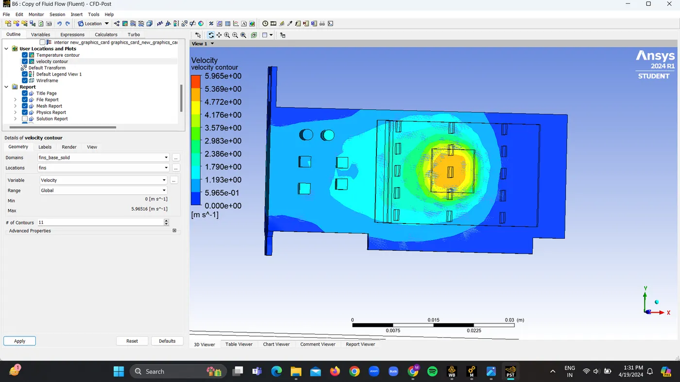
Velocity Contour
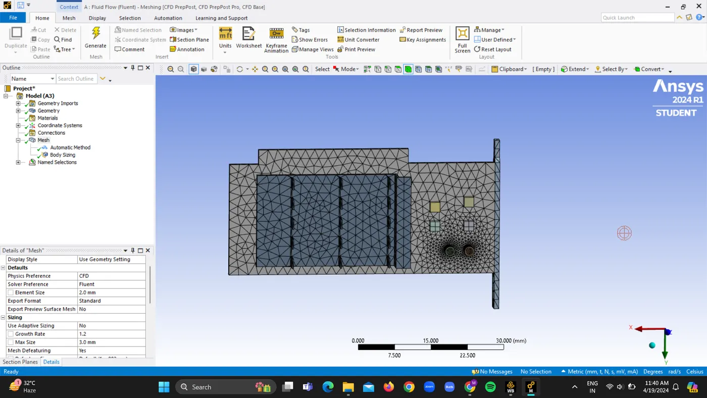
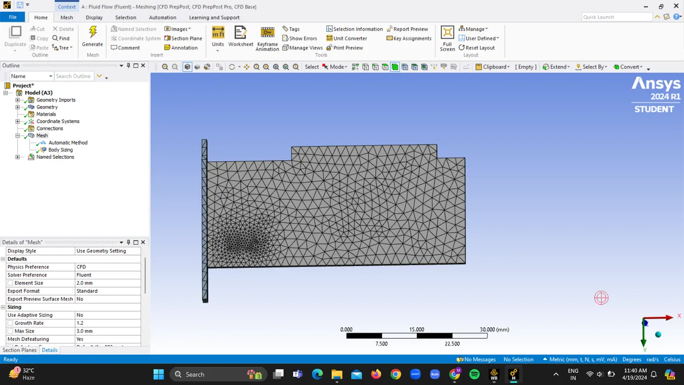
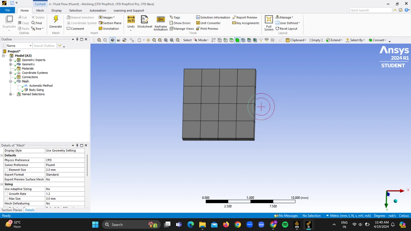
C. For refined mesh of 2mm with body sizing given along with velocity 5m/s
1. Meshing
2.Solving
Residuals:
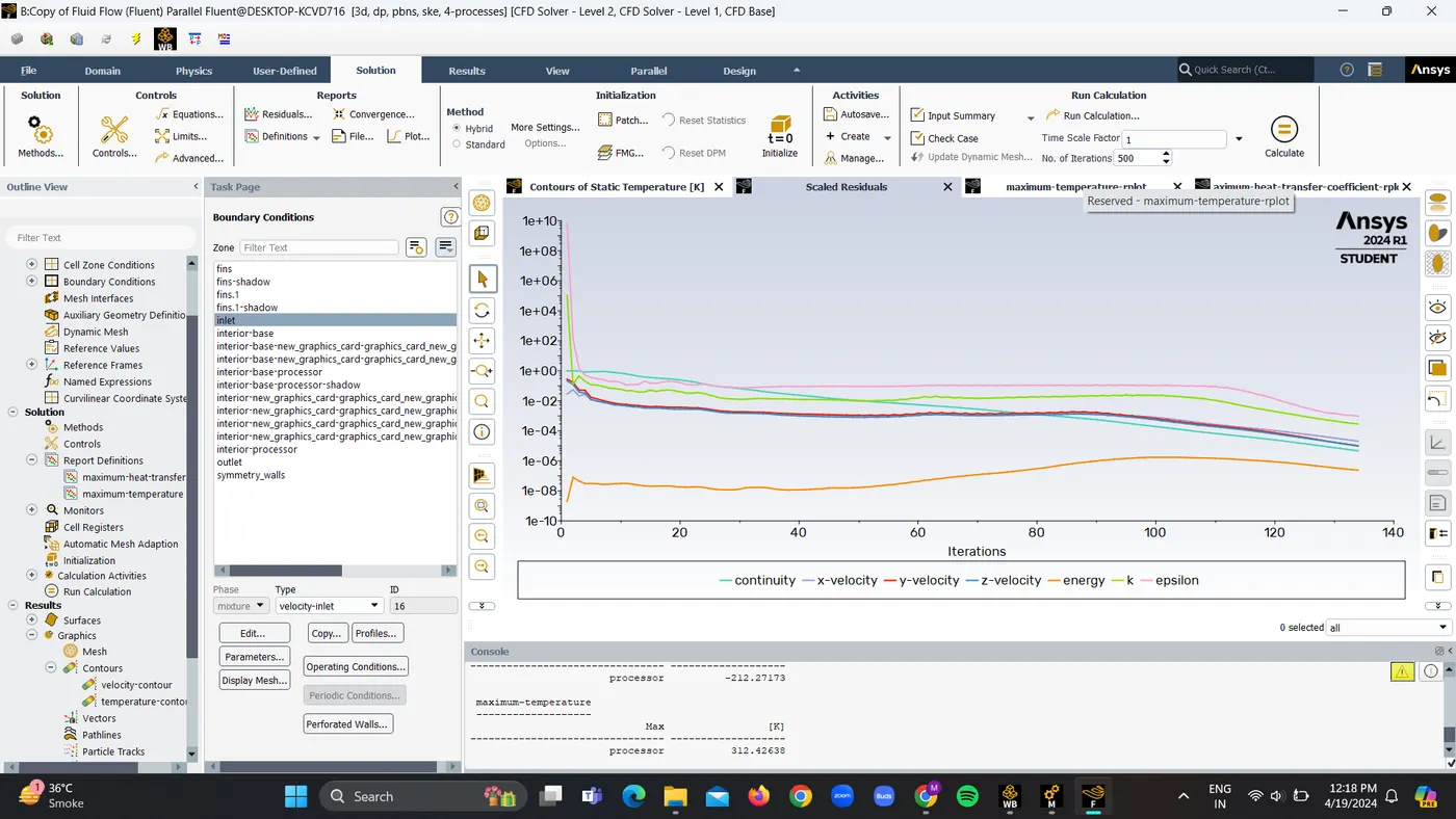
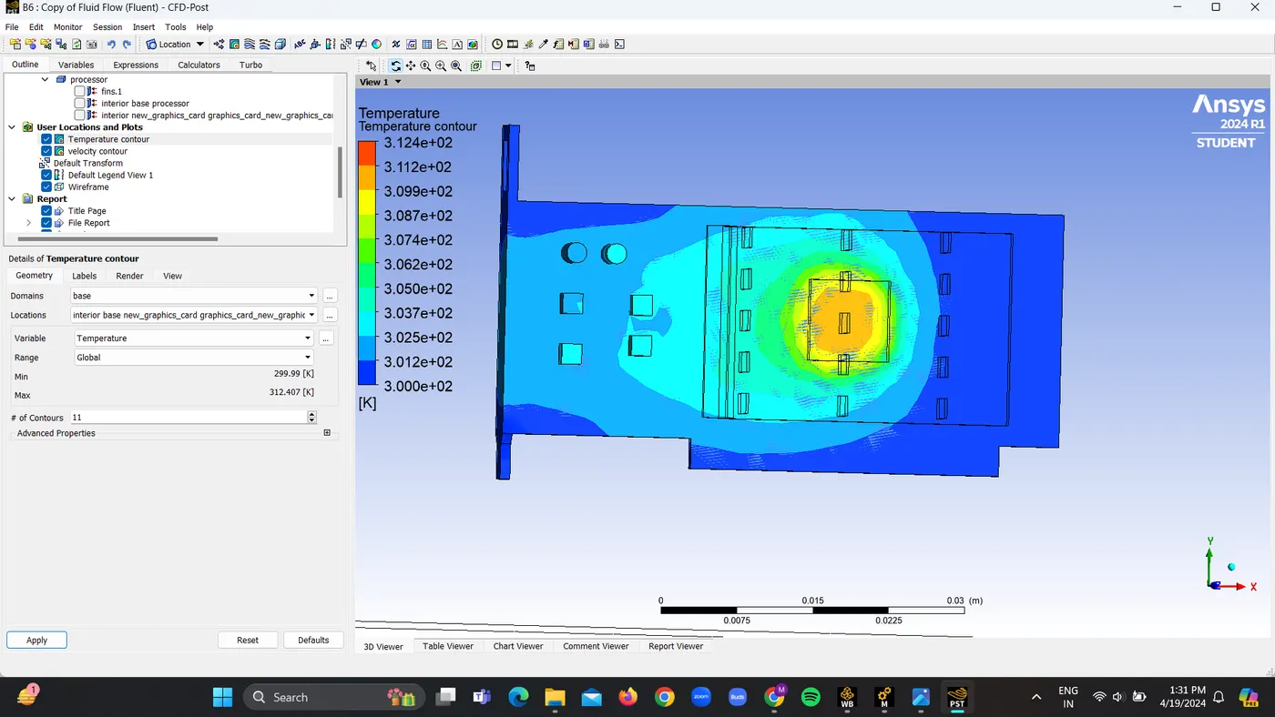
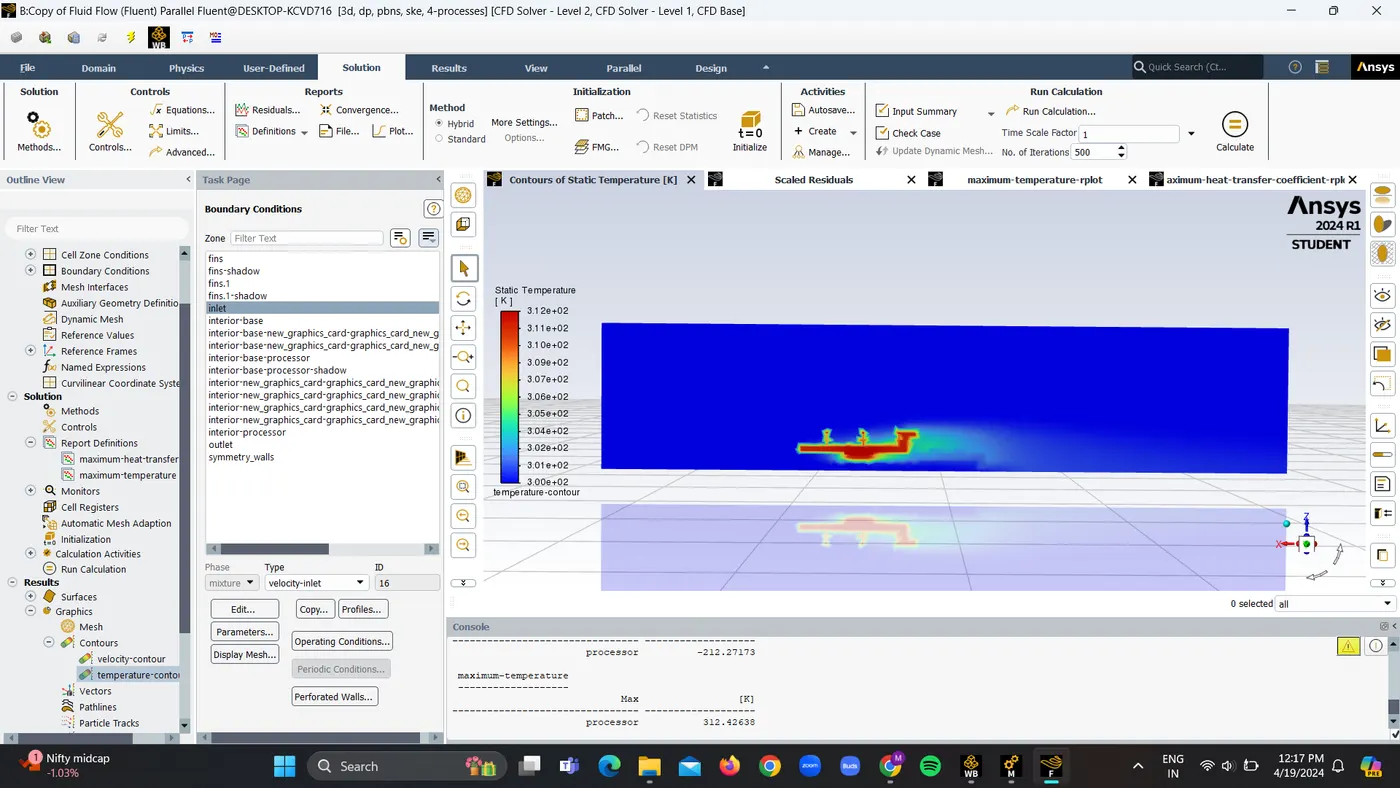
Maximum Temperature is 312.42K
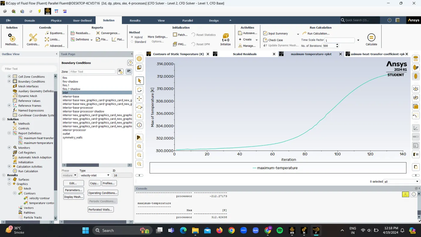
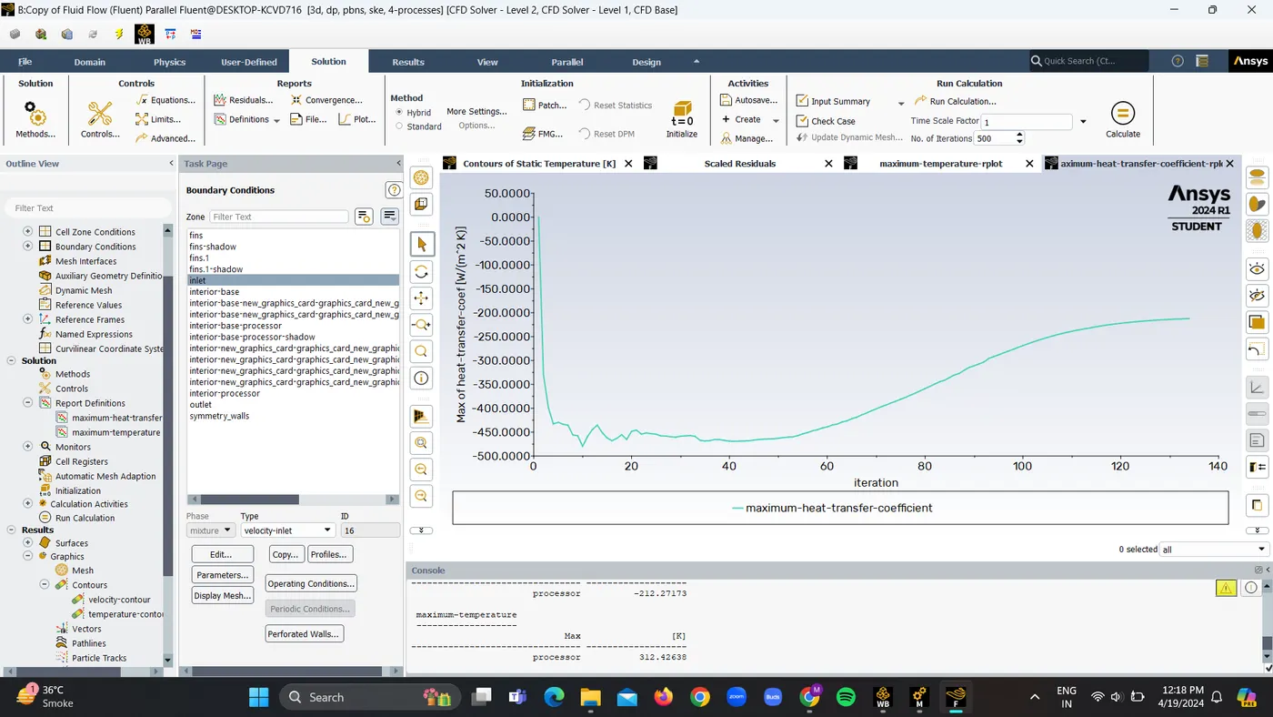
Maximum Heat transfer coefficent is -212.27 W/m2K
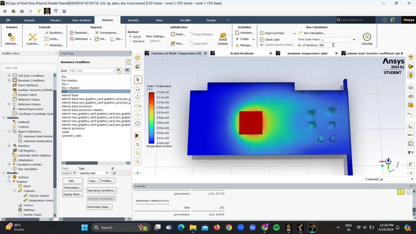
Temperature contour
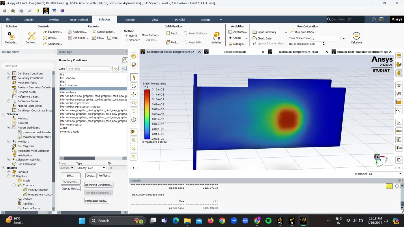
Velocity contour 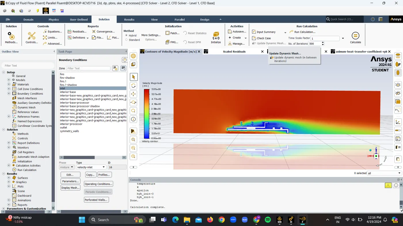
Conclusion:
Inlet Velocity (m/s) Maximum HTC (W/m2K) Maximum Temperature (K)
1.For baseline mesh of 10.289mm 1 -153.46 327.31
2. For refined mesh of 3mm 3 -444.09 300.69
3. For refined mesh of 2mm 5 -212.27 312.42
The accompanying table shows that increasing the input air velocity lowers the average temperature.
The maximum heat transfer coefficient occurs at an input velocity of 5m/s. This observation aligns with the experimental pattern.
Thermal hotspots can be seen around the fin-processor interface and the fin body.
The residual plot shows that the solution has converged.
Mesh refinement for the processor and fins resulted in closer to experimental values.