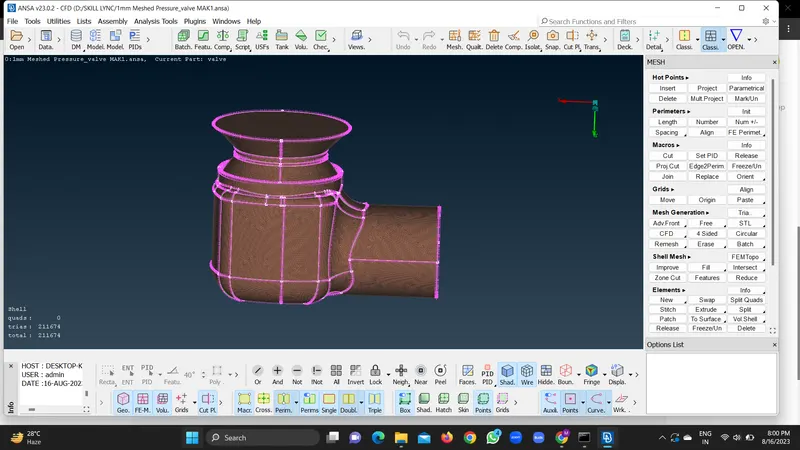
Week 2 Challenge : Surface meshing on a Pressure valve
PRESSURE VALVE:
A pressure valve, also known as a pressure relief valve, is a mechanical device that helps regulate the pressure in a system by releasing excess pressure when it reaches a certain level. It's commonly used in various applications, including steam boilers, pressure vessels, pipelines, and other industrial processes.
The primary function of a pressure valve is to protect the system from overpressure. When the pressure inside the system rises above the set pressure of the valve, the valve will open and release the excess pressure to the atmosphere or a low-pressure zone. This prevents damage to the system and any potential safety hazards that could arise from the overpressure.
Overall, the function of a pressure valve is to ensure that the pressure in a system remains within safe limits and prevent any potential hazards or damage. By releasing excess pressure, it helps maintain system integrity and improve its efficiency.
GEOMETRY CLEANUP OF A PRESSURE VALVE:
Aim: To create the surface or geometry clean up of pressure valve .
Procedure:
1. Set the Resolution of the geometry .
2. Set the Orientation of the geometry according to the flow of the fluid.
3. Study the geometry carefully and then go for the rectification of the errors.Geometry should be watertight model and completely error free.
4. There will be single cons and triple cons appearing in to the geometry. Single cons are said to be free boundaries and Triple cons are considered as cons consisting of 3 or more faces.
5. Select the single cons or Red cons and create new faces . NEW -CONS /FITTED /PLANAR /EXISTING SURFACE-Select the red cons -middle click -check whether the new faces are compatible with the geometry or not- Done.
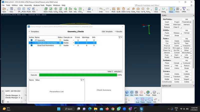
6.Go for the geometry checks from the checks manager.
7. There will be intersection errors in the geometry .So the intersection errors are appearing into the spring .
8. Isolate the spring and column .Set the PIDs .Here there is intersectiion error btw column and spring. so select the INTERSECT option and assign the 1 and 2 group and middle click.
9. It will intersect the faces and ask which face to keep and which faces we should delete.
10. Collapsed cons may appear into the geometry . They are considered as errors. So select HOT POINTS -CLEAN GEOMETRY -BOX SELECT THE CONS - DONE.
11. Execute the geometry checks .concave cons may appear in the geometry due to sharp edges and can be ignored.
12. Geometry is Error Free.
13.Meshing, in the context of computational modeling and simulation, refers to the process of dividing a complex geometrical domain into smaller, simpler elements called "mesh elements" or "finite elements." These elements are usually triangles or quadrilaterals in 2D simulations and tetrahedra or hexahedra (cubes) in 3D simulations. Meshing is a crucial step in various fields, such as computational fluid dynamics, structural analysis, electromagnetic simulations, and more.
The primary reasons for performing meshing are as follows:
-
Numerical Approximation: Most simulations involve solving complex mathematical equations that describe the behavior of a system. However, these equations are typically too complex to be solved exactly. By dividing the domain into smaller elements, you can approximate the behavior of the system within each element using simpler equations. This allows numerical methods to be applied to solve these equations numerically.
-
Visualization: Complex geometries cannot be directly analyzed or visualized in simulations. Meshing simplifies the geometry by representing it as a collection of smaller, well-defined elements. This makes visualization, analysis, and interpretation more manageable.
-
Adaptability: Different parts of a domain may require different levels of detail in the simulation. Adaptive meshing techniques allow the mesh to be refined or coarsened in specific regions based on the simulation results. This increases accuracy where needed and reduces computational costs in less critical areas.
-
Boundary Conditions: Meshing helps define boundary conditions for simulations. For instance, in fluid dynamics, you need to know how the fluid interacts with solid surfaces. Mesh elements along the boundaries help determine these interactions accurately.
-
Accuracy and Efficiency: The accuracy of simulations is influenced by the size and distribution of mesh elements. Properly meshed simulations can yield more accurate results. At the same time, meshing also affects computational efficiency. A well-structured mesh can reduce the number of elements required to accurately represent the geometry, leading to faster simulations.
-
Compatibility with Solvers: Many numerical solvers are designed to work with finite element or finite volume methods, which rely on meshed domains. Meshing makes it possible to translate the governing equations of a physical system into a numerical form compatible with these solvers.
CONCLUSION: We conclude that the geometry should be error free to be considered for the next step Meshing.Snapshots of clean geometry of pressure valve are given below:
In summary, meshing is a crucial step in numerical simulations because it enables the representation of complex geometries in a format that numerical methods can handle. It allows for accurate approximation of solutions, visualization, and efficient computation, which are essential in various scientific and engineering applications.
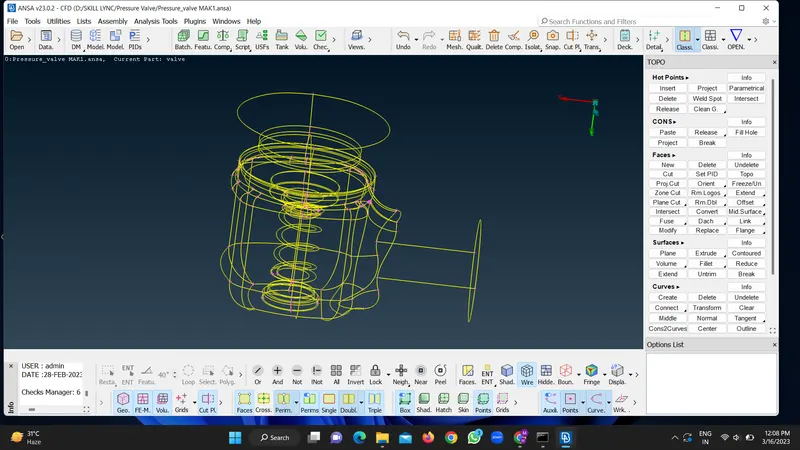
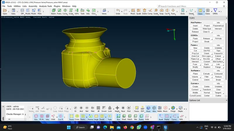
5mm Meshed Pressure Valve:
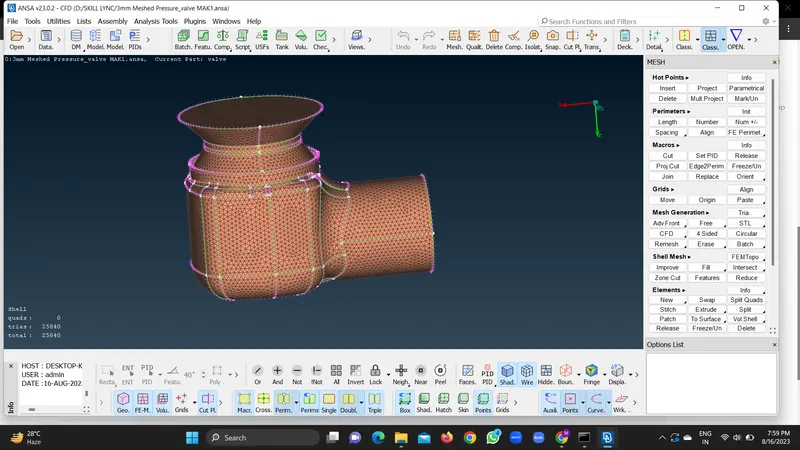
3mm Meshed Pressure Valve:
1mm Meshed Pressure Valve: