Week 3 Challenge : CFD meshing on Turbocharger
TURBOCHARGER: It is an automotive component that harnesses exhaust gas energy to enhance an engine's performance. It comprises a turbine and a compressor connected by a shared shaft. As exhaust gases exit the engine, they drive the turbine, which, in turn, powers the compressor. The compressor pressurizes the incoming air, enabling the engine to burn more fuel efficiently and generate higher power levels without increasing engine size. This technology optimizes power output, improves fuel efficiency, and enhances overall engine performance, making it a pivotal innovation in modern internal combustion engines.
GIVEN:
- Blade stage-1 = 1 mm
- Blade stage-2 = 1 mm
- Impeller = 2 mm
- Shaft rotor = 1 mm
- Turbo casing = 5 mm
- Compressor casing = 5 mm
- Inlet casing cover = 5 mm
REPORT:
AIM: To make a clean geometry and meshing of Turbocharger and with zero errors.
PROCEDURE:
1. Set the Resolution of the geometry .
2. Set the Orientation of the geometry according to the flow of the fluid.
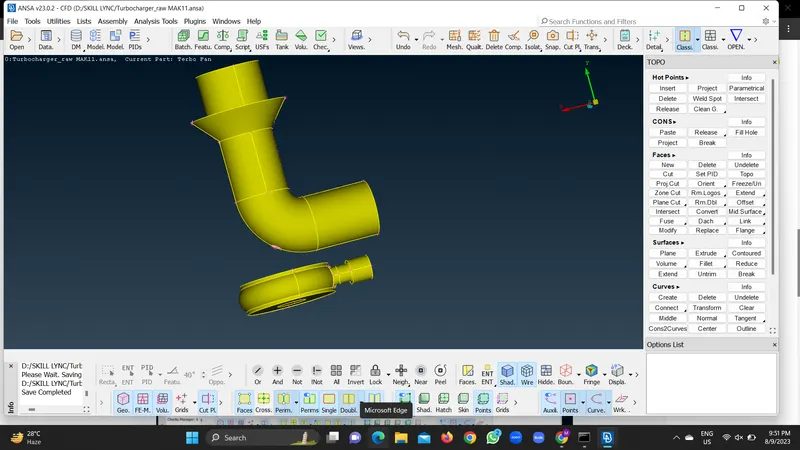
3. Study the geometry carefully and then go for the rectification of the errors.Geometry should be watertight model and completely error free.
4.In Turbocharger , we are going for the internal flow analysis, therefore the outer parts should be yellow and the inner parts of the turbocharger should be grey . Thickness shoould be removed from the turbocharger.
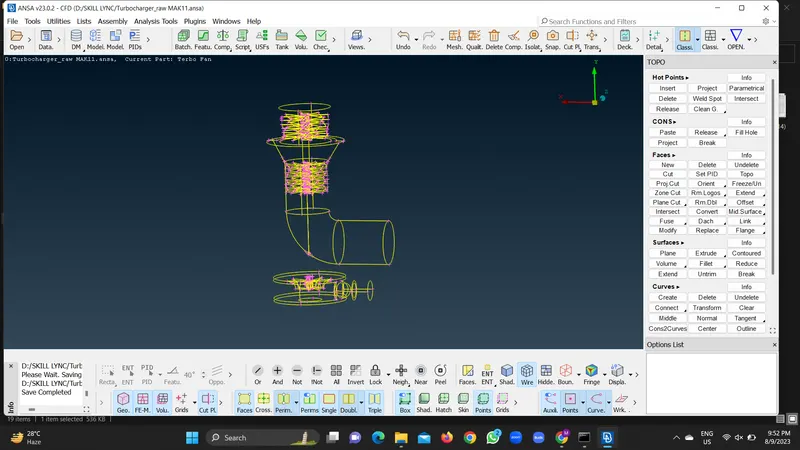
5. There will be single cons and triple cons appearing in to the geometry. Single cons are said to be free boundaries and Triple cons are considered as cons consisting of 3 or more faces.Faces should be closed as we have to define a voulme.
6. Intersection errors will appear on the shaft and turbine parts . The connecting shaft in turbocharger should be a single volume. We need to delete the inner or overlapping faces from the shaft.fluid flow problems
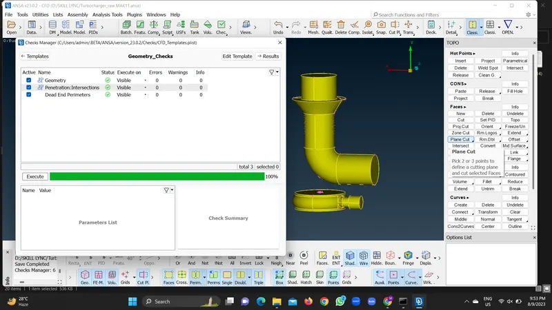
7.Go for the geometry checks from the checks manager.
8. Overlapping faces should be deleted from the turbine and shaft parts for clean geometry.
9.Check the geometry checks and intersection errors and hit the TOPO on turbine parts as Red COONS may appear.
10. Geometry is error free.
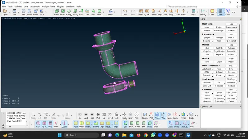
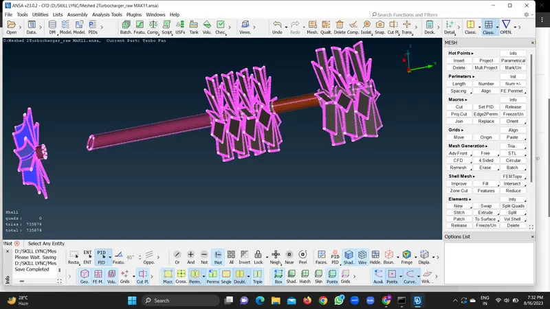
11.After Geometry cleanup , Meshing is required to be done.
12.We want to study fluid flow problems, so we need governing equations which are into partial differential form.We have to convert these PDEs intoi Algebraic Eqns by using Taylor Series.
13.Therefore we need to have discrete number of nodes to do so.
CONCLUSION:
1. Mesh breaks down the object into smaller cells with a distinct number of nodes.
2.By this , the geometry of any object is accurately captured.
3.By Meshing , PDEs are applied to each individual cells.
SNAPSHOTS: