Week 4 Challenge : CFD Meshing for BMW car
OBJECTIVE: Geometry cleanup and meshing of the BMW M6 model for CFD using ANS
AIM: As we will be meshing the BMW M6 model in the wind tunnel, it must first be cleaned and all topological flaws corrected, therefore we must first identify and correct all geometrical defects in this BMW M6 model. During this project, we will use a variety of new tools including extend, project, CONS paste ,etc and symmetry utilizing the transform tool.
PROCEDURE:
1.CLEANING UP TOPOLOGICAL ERRORS IN THE MODEL.
Because the model contains numerous flaws, we will begin with a simpler side, namely the left side of the vehicle.
Correcting the projection and open geometry error.
We'll start with the left front entrance, which has an error of no intersection, no cons, and an open geometry. To correct this issue, we shall project the cons onto the surface where the join is to be created and lengthen the face. For open geometry, we must design a new surface and, after correcting the portion, erase any unneeded hot points.
Steps for Projecting a Con on a Surface
In topo mode,
Under cons, select the project.
Choose the cons to be projected on the surface.
Select the surface where we want to project the con.
With a middle mouse click to confirm the selection, the cons are successfully projected into the surface, resulting in a new suface.
Steps to extend the face of the geometry
Under faces, select EXTEND.
In the choice list, we must indicate the range of the extension of the face.
Select the single cons of the surface to be stretched, then use the middle mouse click to confirm your pick.
Choose the target surface on which the extension will be made.
A middle mouse click automatically creates an enlarged surface.
How to remove unnecessary HOT POINTS
When in topo mode
Beneath hot points
Choose "Delete."
The stray hot points will all be automatically chosen when you use the left mouse click and drag to construct a box and select the geometry.
To finalize the selection, click in the middle of the mouse; any superfluous hot points will be removed.
Transforming volume elements from BMW M6 parts into surfactant elements.
We only need the surface elements of the geometry,surface meshing, volumetric meshing, and CFD. Volume surfaces of the geometry are not necessary.
The process of eliminating the volume surface will be used to fix some elements, such as the front and rear windshields, headlights, backlights, windows, over rear view mirror, etc. We must delete such volume entities by choosing the parts under PID and utilizing universal delete in ENTITY mode. Eventually, the only entity that matters for CFD will be the front surface.
To make the geometry invisible and the part's front surface invisible, go to the NOT (–) Mode.
Choose the option for universal deletion.
Choose the part's interior irrelevant volume surface.
After confirming the selection with a middle mouse click and turning on visibility, the surface object will be the only thing remaining.
Geometry cleaning for the BMW M6's side vent :
There were numerous surface irregularities and numerous topological problems in the BMW M6's front side vent. As we may resolve surface glitches by removing unnecessary surfaces from it using universal delete, we will begin the geometry clean up process.
Next, we must design a mesh volume so that it resembles a mold. This means that the part's front and rear must not have different volumes because meshing depends on them.
Create the surface so that the error may be fixed. We only need the mold, not the entire volume, and all stray hot spots should be eliminated.
additionally use the cut and universal delete tool to remove any irregularities, then construct new surfaces to create the front side vent's clean surface geometry.
The current face will be divided and a new cons will be created under the Faces Select Cut option. Select parametric from the option list and check the heal cut box.
To choose the required hot spots, use the left mouse click.
After verifying the selection with a middle mouse click, the surface is split to reveal a new DOUBLE CONS.
Eliminate half of the BMW M6 model. Click in the middle to confirm your pick. Only the remaining half of the model needs to be cleaned at this point.
FIXING THE TOPO ERRORS IN THE MIDDLE GRILL UP FRONT:
There will be a single CONS at the removed portion of the grill because of the single surface, as the model is being deleted in half. Now, we will use double or triple CONS to correct the problems.
Since the middle vent contains the double and triple CONS, we must remove the excess surface in order to transform it into a hollow shape, which is important for CFD External Flow Analysis.
First, we will use the Universal Delete option to remove the additional surface.
When several cons are passing in close vicinity, the release tool under Cons eliminates the cons and, if accessible, deletes stray hot points.
Once more, we must paste.
Procedure for CONS Paste:
Click Cons and choose Paste tool.
Click with the left mouse button to select the two cons that are apart from one another.
When you confirm the selection with a middle mouse click, the single CONS will become double CONS.
In the event that the geometry exhibits any irregularities, make sure to erase and re-create the geometry until the BMW's center grill is repaired.
- CLEANING THE ENGINE INTAKE GRILL'S GEOMETRIC ERRORS:
In order to remove the Topo errors from the engine intake grill, we must first remove all volume surfaces, or volume entities, leaving only the desired surface element. Using Project under Cons, Cut under Faces, Extrude under Surfaces, and new clean face creation, we will obtain the engine intake grill's cleaned geometry. Lastly, we will turn it into hollow cleaned geometry with double CONS.
Actions
First, we will use the universal delete option to remove the additional surface.
Surfaces The back side of the grills are glided in order to provide a smoother geometry and remove any remaining superfluous surfaces.
Project the engine intake grill shown above on the grill's front surface, cut it out, and remove the relevant portion.
To achieve a cleaner hollow geometry, add new surfaces to the model.
Procedures for GLIDE:
Go to Surfaces and select EXTRUDE.
Holding down the mouse, choose Glide under Extrude.
For the extrusion, choose the first CONS and then the second CONS.
To confirm the selection, use the middle mouse click.
CLEANING THE EXHAUST, WHEELS, AND BODY'S GEOMETRIC ERRORS:
As we begin the wheel cleanup, we can delete the wheel on the right front that has a lot of topological flaws and create symmetry in the front wheels, even though there aren't many topological problems in the wheel shape overall.
The body and exhaust are next. The exhaust does not have any significant Topo errors, but the car floor geometry has a lot of unnecessary surfaces created. To avoid geometrical errors, we must use Universal Delete to remove the car floor surfaces and create new, cleaner, smoother surfaces using the New under Faces option.
MODEL BROWSER AND PID ASSIGNMENT
Because there are many parts in this geometry, we must separate them in order to use them effectively. To do so, we will use MODEL BROWSER; because the parts are described with part codes in the property menu, we must separate the comparable parts in order to work effectively on each component. Following that, we will combine distinct PIDs into a similar PID with similar colours to make it easier to recognize them.
STEPS
Goto MODEL BROWSER option
Set part
Drag and select the model
Click on new part
Rename the part. (for e.g. Body, wheels etc.)
Model folder of each part will start visible on the model browser dialog box
Click ok to confirm the selection
Now we will be taking care of the PID’s for all parts by segregating the PID of the model
Goto set PID
Under the properties select visible it will show only visible PID
Then convert different PID’s into one similar PID by changing their colour for identifying and working on them effectively.
Geometry Checks of the Model BMW M6:
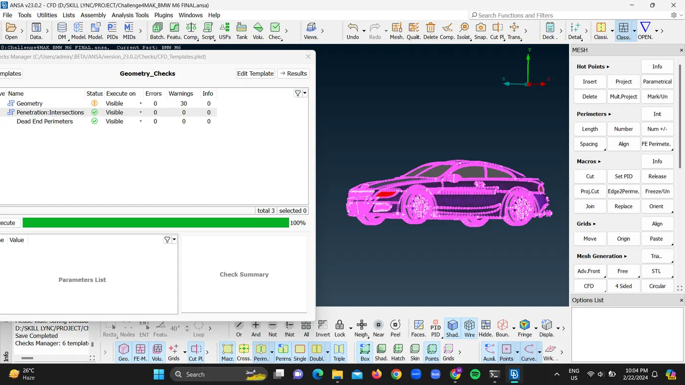
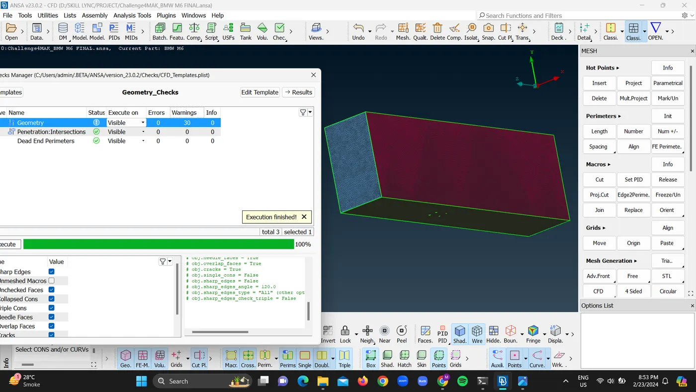
After addressing all of the topological mistakes, we will run the geometry checks to see if there are any similar errors left, such as the RED CONS errors. This is because one-half of the model is being removed to achieve symmetry.
Surface Mesh of the Model BMW M6:
After performing geometry tests, we may proceed to mesh the model using the mesh module, which requires us to mesh the model with certain mesh lengths assigned to each part.
STEPS
Go to Model Browser.
Click on Show Only.
Give the following mesh length under Perimeters, and under the selection box pick perimeters to assign the length of every model geometry excluding the BMW logo.
Assigned Mesh Length
Body 3mm
Lights 4mm
Grills 1mm
Tires and rims 2mm
ORVM 2mm
Windows 2mm
Exhaust 3mm
BMW logo 1mm
ELEMENT TYPE TRIA
STEPS TO ASSIGNING MESH LENGTH FOR BMW LOGO
We must choose the logo under Macros.
Using the left mouse click, select the entire region.
Only the logo will be picked when we utilize the right mouse click to select the unnecessary portion of the hood.
Provide the mesh length value.
To confirm the choices, click "OK."
Mesh will be generated throughout the model once the mesh length has been reassigned. Go to Mesh Generation, select Free mesh, and then select Visible.
MESH CHECKS OF THE BMW M6 MODEL
following completing surface meshing on the BMW model, we will run surface checks; following execution, many defects will be revealed that are undesirable and must be corrected to improve mesh quality.
SYMMETRY OF THE BMW M6:
Because the model is precisely aligned on the axes (x, y, and z), we can construct a symmetry of it. To begin, we will delete half of the pre-existing geometry model from the center because mirroring or symmetry occurs in space and does not like importing geometry. This tool will make our job much easier because we will be eliminating the model half from the center and cleaning all of the topological defects in the remaining half, followed by symmetry under the Transform tool, which will automatically finish the model's whole cleaned geometry.
As the topology and meshing clean-ups are completed, we will use the transform tool to create symmetry for the model's body and wheels using 3 point plane symmetry. In this sort of symmetry, we must choose a symmetry line by selecting three points that define a plane but do not lie on a straight line. This type of symmetry results in an extremely accurate symmetry of the model.
STEPS
Select the Transform option from the top menu bar.
To clone an entity, pick 3 point plane symmetry from the option box.
Select a symmetry line in which the point should define a plane but not be on a straight line.
Confirm the selection with a middle click.
As the symmetry of geometry is accomplished but single cons are still visible, the geometry should be pasted with the frame using Paste under the Cons.
To paste cons together, go to "Cons" and select paste.
Left mouse click to select the CONS of the geometry with the frame's cons.
Click the middle button to confirm.
Wind tunnel for performing CFD of the BMW M6 model:
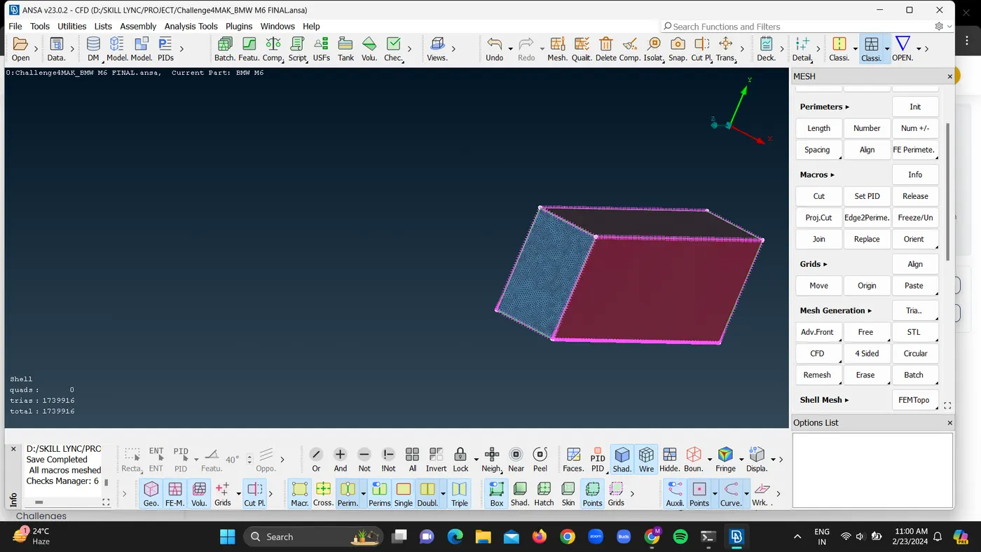
To perform external CFD analysis, we must first establish a closed volume known as a wind tunnel and place the model within it for analysis. We need to examine the car's approximate length value; we will measure the length with the measure tool.
Dimensions of wind tunnel
4X FRONT OF CAR
6X REAR OF THE CAR.
3X TOP OF THE CAR.
Bottom close proximity with tires 1X from the center plane for left and right sides.
STEPS
Measure the length of the car.
Make a new point using Relative under Points.
Creating the point at a distance of 4X implies 4 times the length of the vehicle (1300 x 4 = 5200).
Set the value for the z axis to 5200; a new point will be generated at this distance.
Under Curve: Select New.
The curve will be formed after selecting both points with the left mouse click.
To change the direction of the points and curves, we must maintain the magnitude constant, but the (+, -) sign will indicate the direction, like in the case of generating the left and right sides of the wind tunnel.
We know that a plane requires at least three points, therefore we will build two more points from the point we established. For example, if we are designing for the left sides of the wind tunnel, we will simply set values for the y-axis and z-axis because the value for the x-axis has already been provided for that distance.
Now that the plane is formed, we can create the new wind tunnel surfaces.
Under Surfaces: Go to the plane.To confirm, click on the three formed points using the middle mouse button.
Drag it manually to make a new surface for the wind tunnel.
If surfaces need to be resized, we will do it under surface select resize.
Similarly, we can repeat the previous technique to generate all of the points and curves around the car model based on the specifications specified above.
As all four sides of the wind tunnel are closed yet surfaces are penetrating each other, we will intersect the face with the intersect tool under faces and delete the irrelevant outside surface with universal delete. As our wind tunnel has been successfully established, we will erase all of the points and curves by selecting delete under Points and delete under Curves. We will attain a clean wind tunnel.
We have already generated a new PID for wind tunnel. Now, we will construct a distinct PID for wind tunnel inlet and outlet using Set PID under faces, click on new to set new PID as Wind tunnel Inlet and Wind tunnel Outlet.
Now we'll go to the mesh module and set the mesh length for the wind tunnel. As a lot of flow activity will take place on the floor of the wind tunnel near the vehicle, we will assign a mesh length of 20 for finer mesh utilizing Length under Perimeters.
The wind tunnel pillars will be assigned a length of 50 since the flow activity is lower near the pillar, allowing us to apply a coarser mesh to the pillars.
The top of the wind tunnel is assigned a mesh length of 100 because it is a boundary layer and a free stream flow parameter, therefore a detailed mesh is unnecessary.
Because the mesh lengths are so short, meshing the wind tunnel can take a long time, thus before meshing, we will use a Spacing tool under Perimeters to divide the mesh in increasing or decreasing order, the division will not be constant throughout the surface.
Steps for using the spacing tool in the wind tunnel's Side faces :
Under Perimeters, select Spacing. A spacing input box will display.
Select geometry.
Under geometry, we need to enter a factor that is greater than one, so we enter 1.1; dmin is the value of the minimum node distance, which is 20 in our case; and dlimit is the maximum node distance, which is 100. An arrow will be visible, indicating the incremental direction.
Click OK, and the spacing will be produced.
Now we're ready to mesh the model with Free or Spot Mesh under Mesh Generation.
Steps
To generate a mesh, go to Mesh Generation and pick Free or Spot Mesh. Then, left-click and drag the model to select it. Finally, middle-click to confirm the mesh.
CONCLUSION:
Geometry clean-up and meshing of the BMW M6 model was successfully done for external CFD study in the wind tunnel using ANSA.
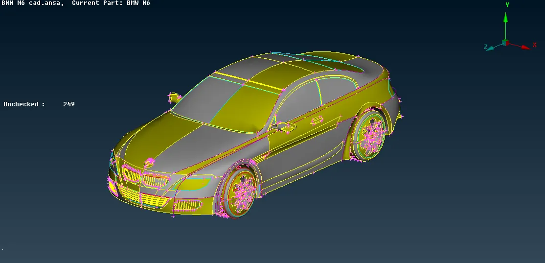
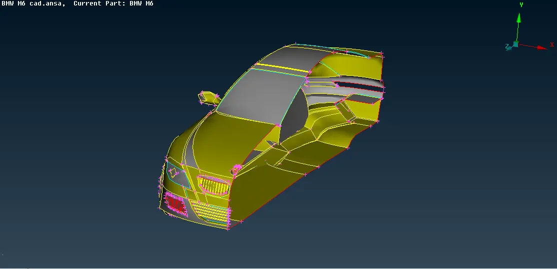
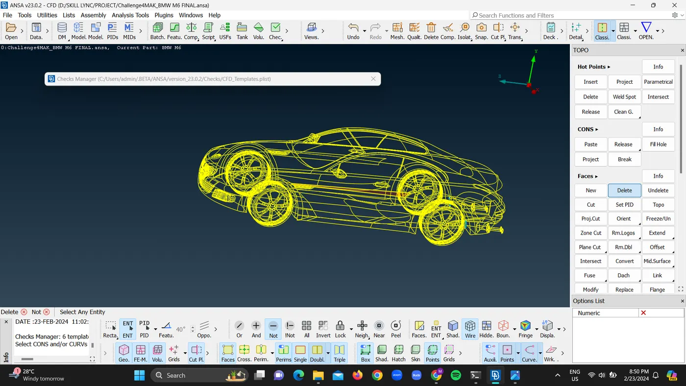
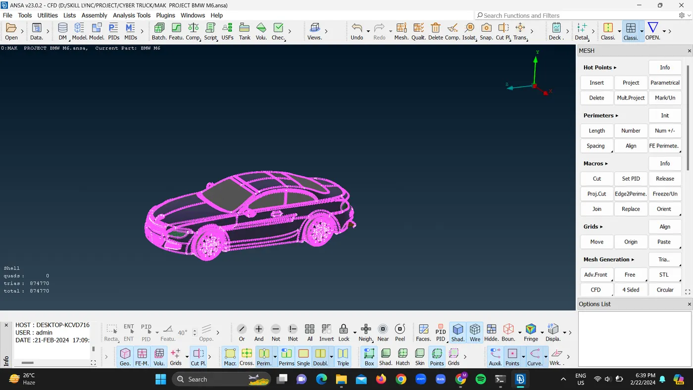
SNAPSHOTS OF THE MODEL:
LINK:
https://drive.google.com/file/d/1ABRX--ZJB3YDgr-ehLhEfX286rcEovSI/view?usp=drive_link
https://drive.google.com/file/d/1ABRX--ZJB3YDgr-ehLhEfX286rcEovSI/view?usp=drive_link