Week 6 - CHT Analysis on a Graphics card
Aim: Is to preform the steady-state CHT analysis on a graphics card.
Objective:
- Run the simulation by varying the velocity from 1m/sec to 5m/sec for at least 3 velocities and discuss the results.
- Find out the maximum temperature and heat transfer coefficient attained by the processor.
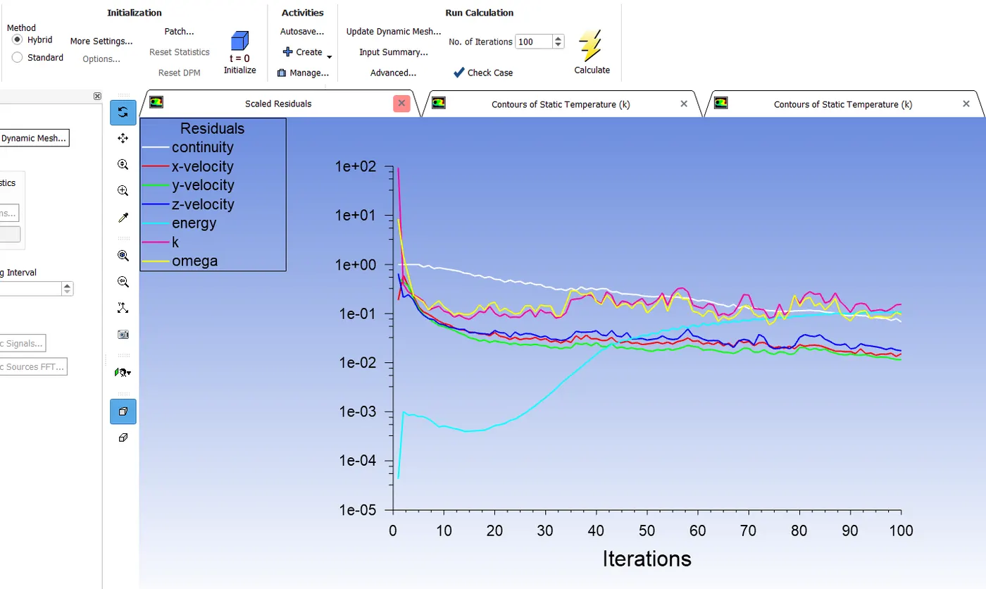
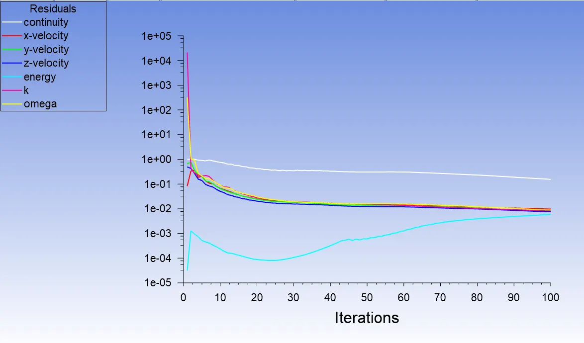
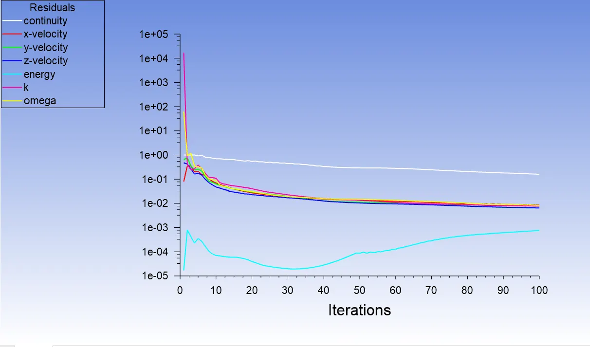
- Prove that the simulation has achieved convergence with appropriate images and plots.
- Identify potential hotspots on the model.
Body of content:
The Conjugate Heat Transfer analysis type allows for the simulation of heat transfer between solid and fluid domains by exchanging thermal energy at the interfaces between them.
Geometry
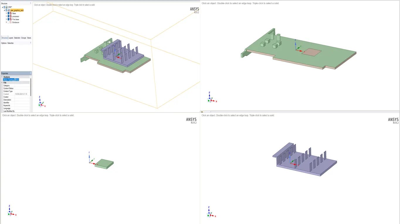
First, we load geometry in spaceclaim and then we perform shar topology between them as shown in figure below.
Mesh setup
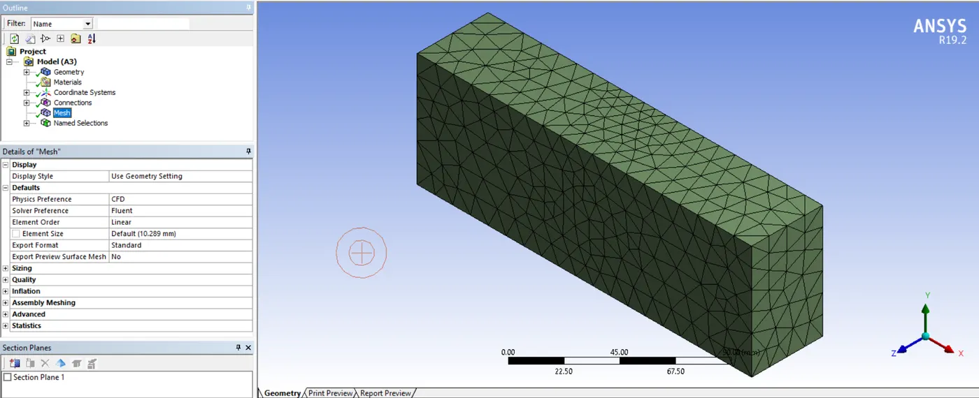
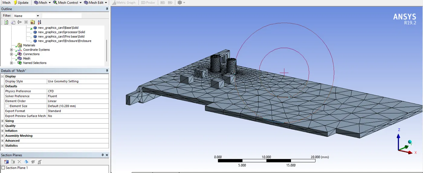
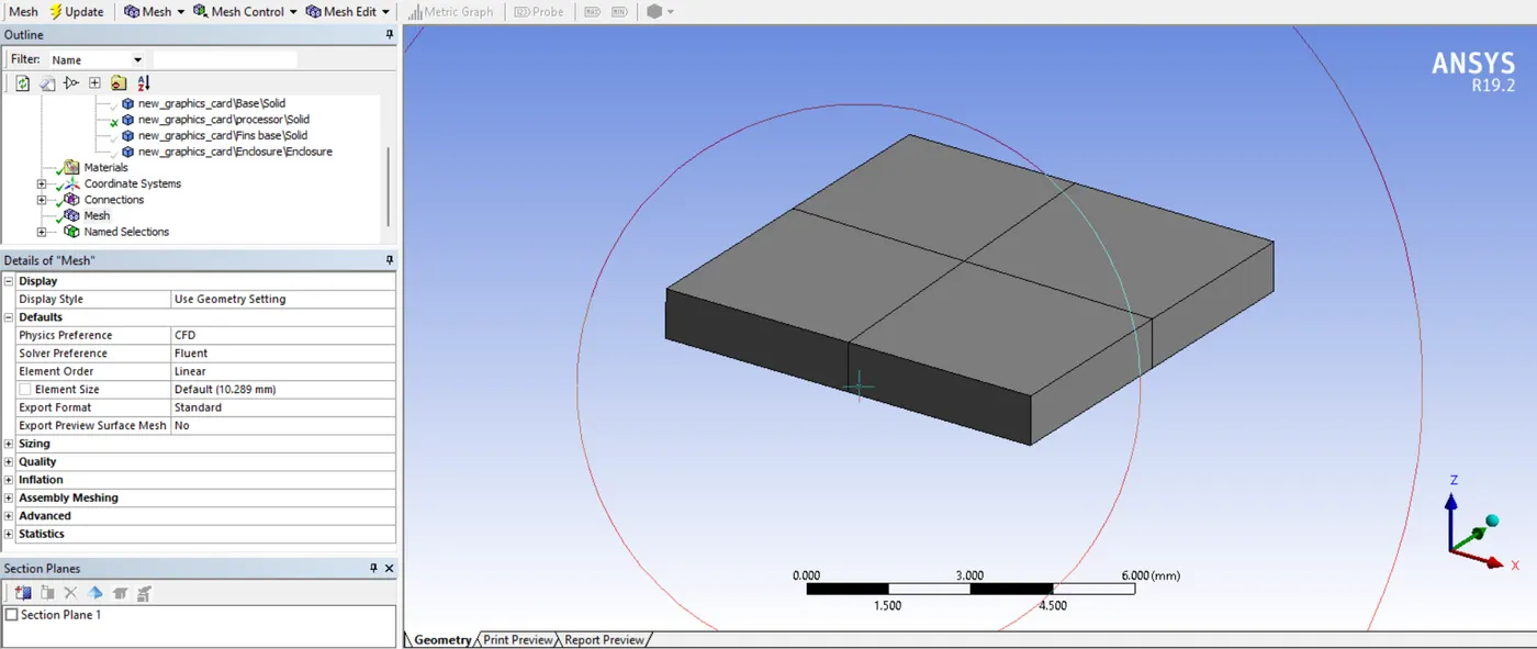
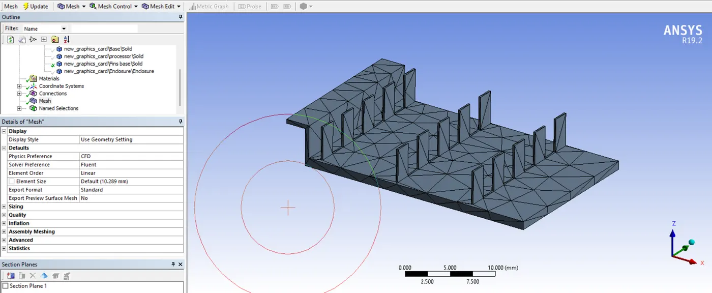
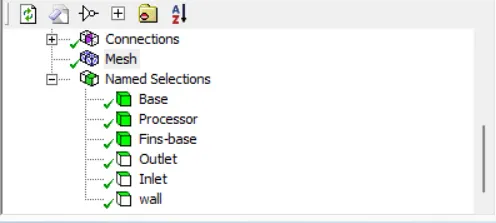
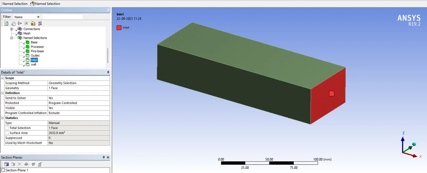
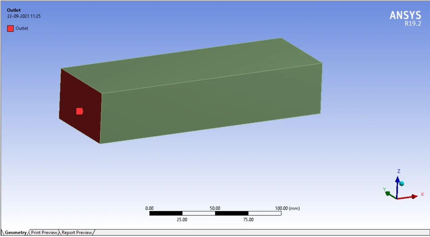
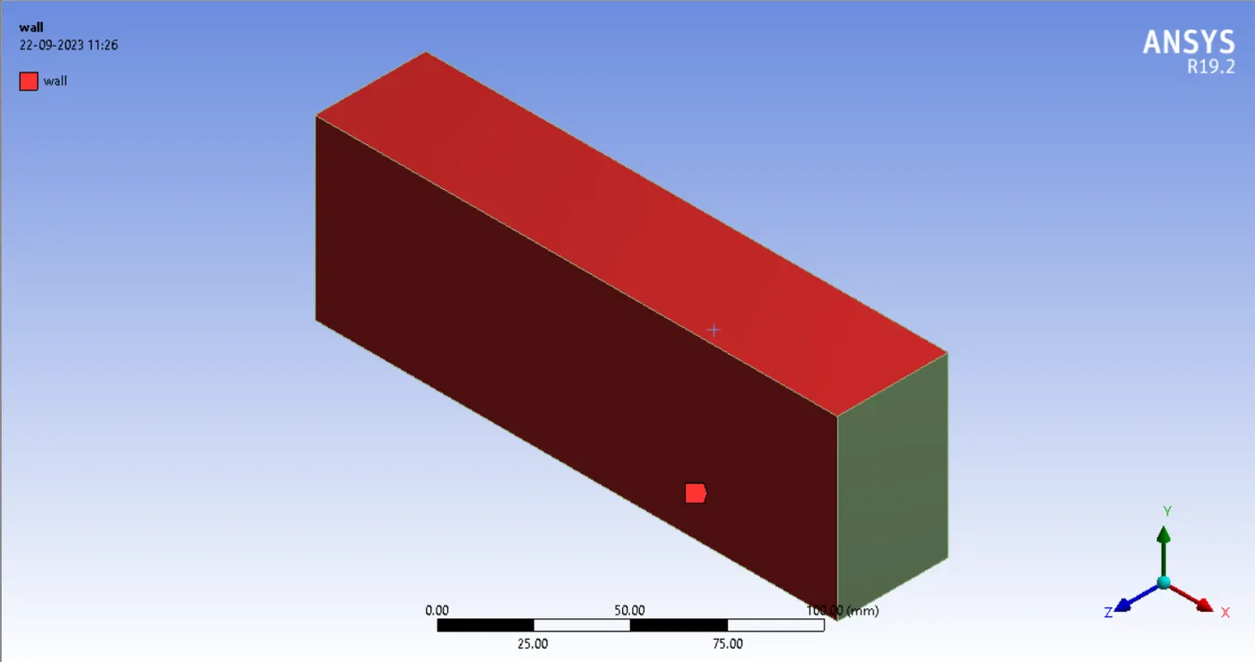
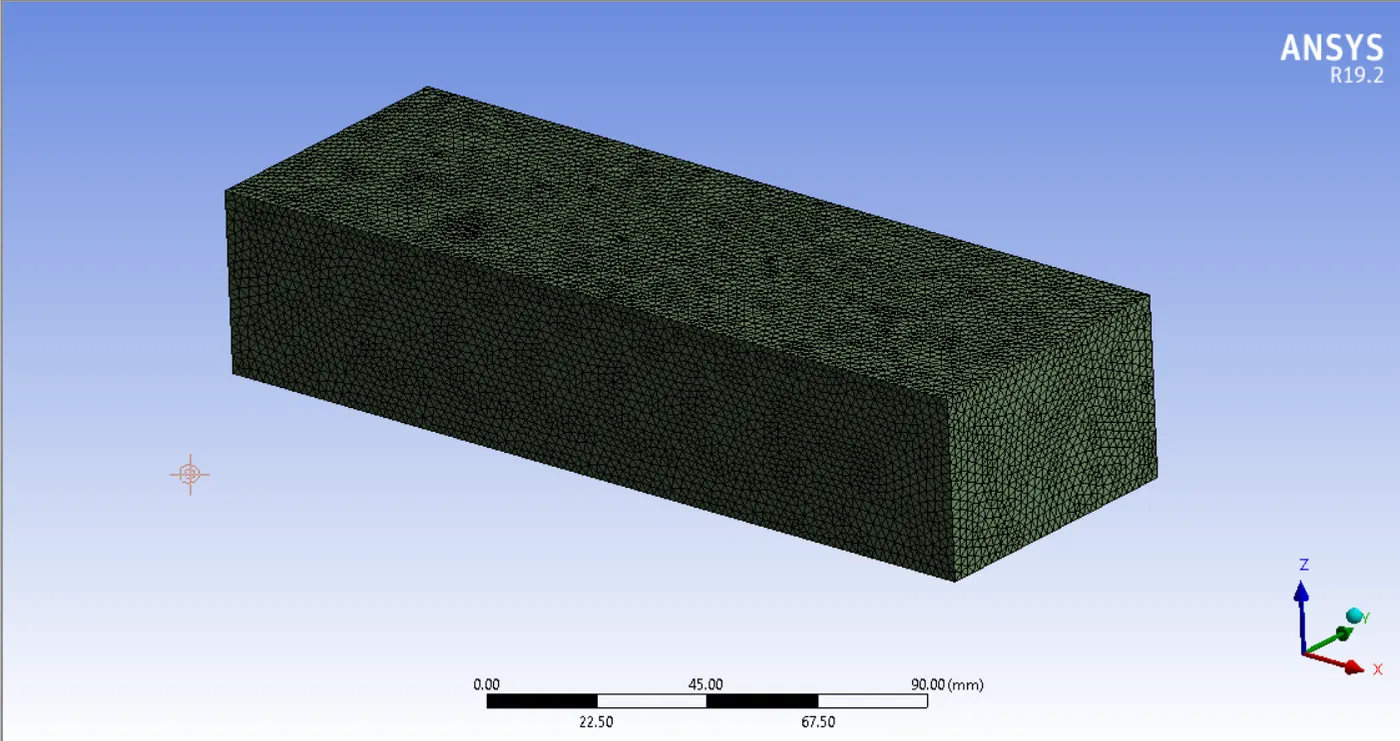
Here we just provide default mesh by system, also we have given the name for boundary condition as shown in below figure.
Enclosure:
Base:
Processor:
Fins -base
Named selection:
Inlet:
Outlet:
Wall:
Setup
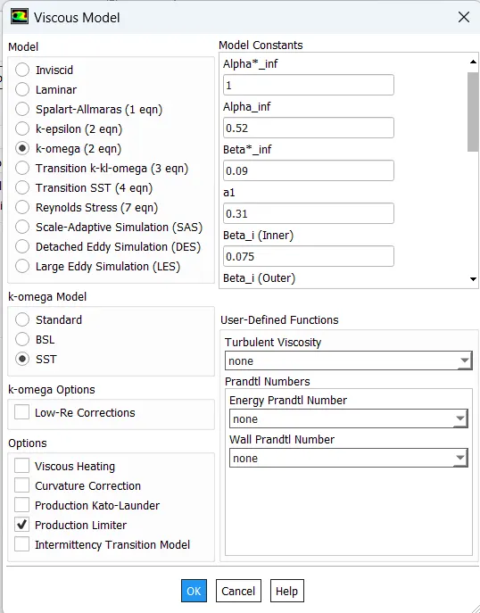
Now here we go with pressure-based solver and with energy equation we select k-omega sst for our simulation, as shown in below figure
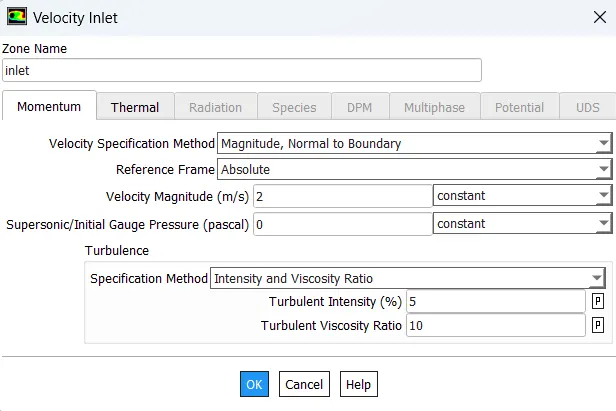
Our next step is to provide inlet boundary condition
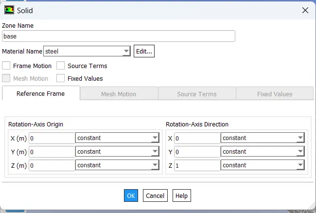
Now as this is CHT analysis on chip we provide several materials for our analysis which are steel for base, aluminium for fins base, copper for processor also in processor we know power consumption is very large so we consider heat generation in it is around 859375000 W/m^3 and for enclosure we simply take air, as shown in figure below is the mention material respectively.
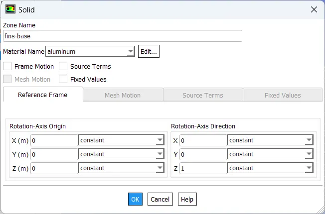
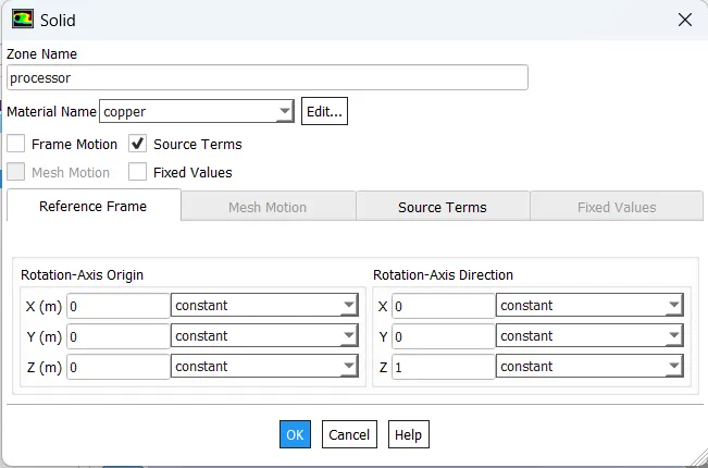

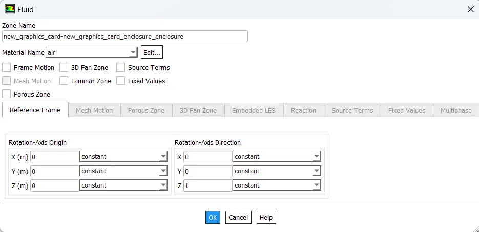
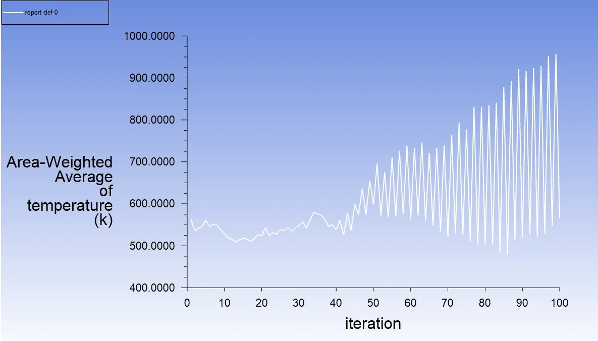
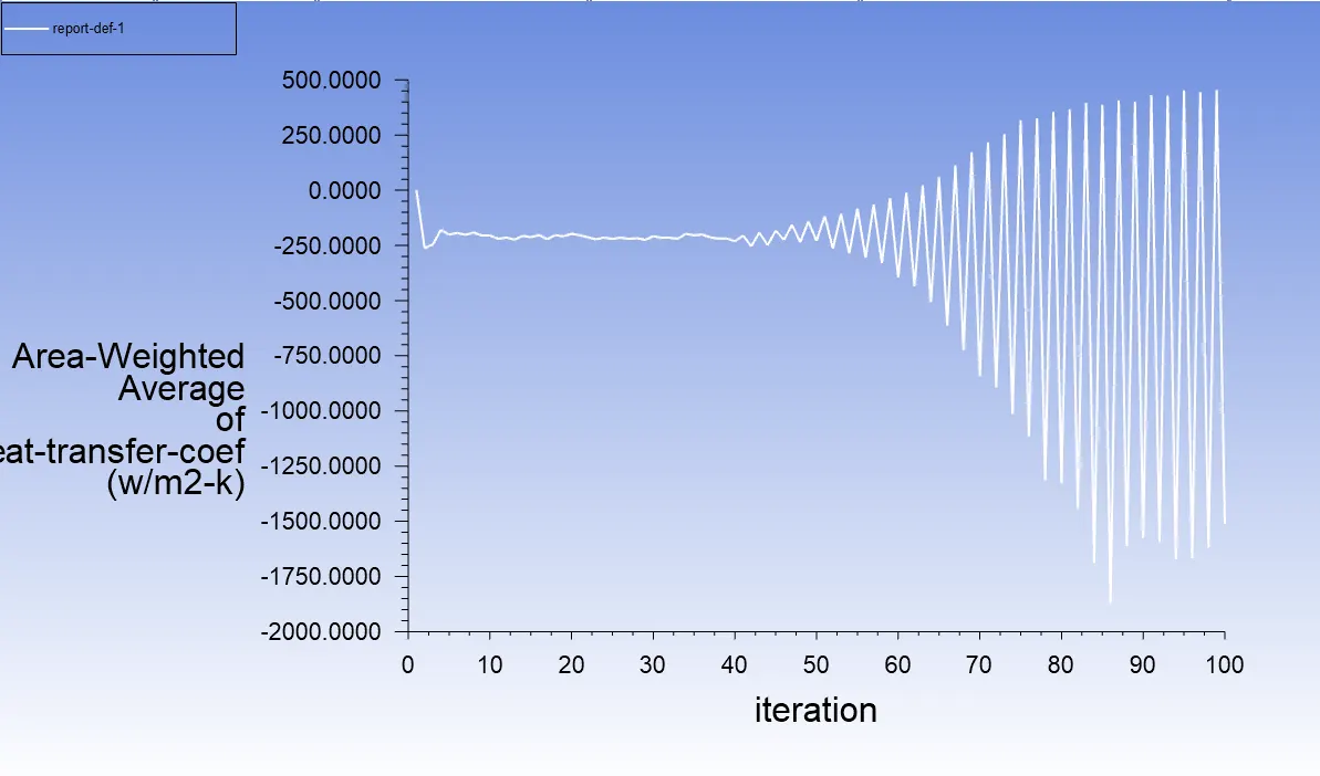
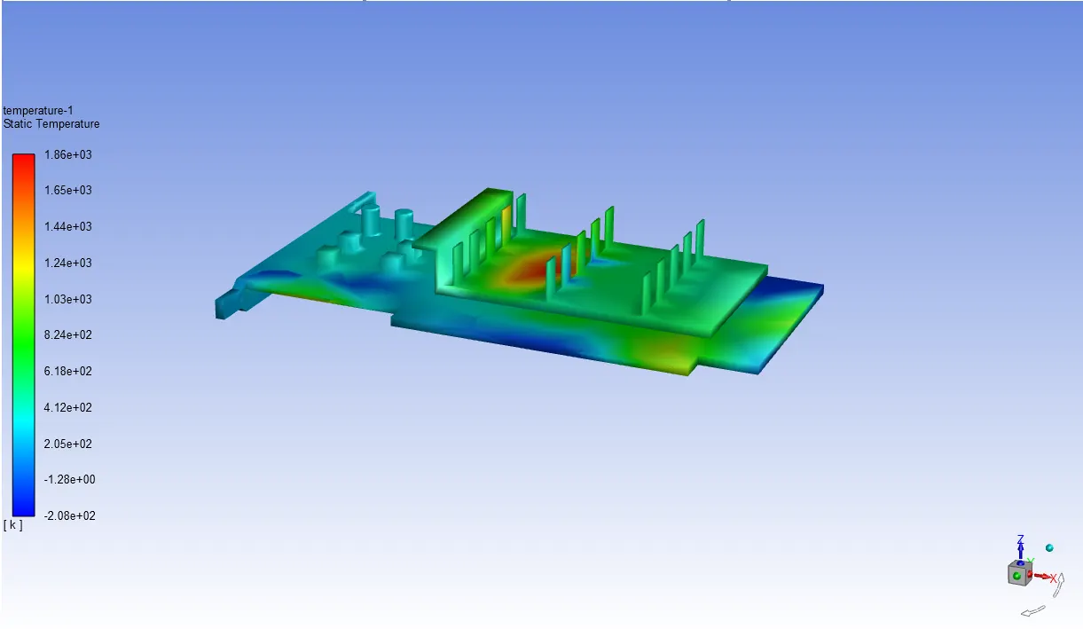
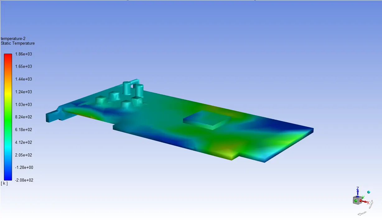
After the setup we go with hybrid initialization and run our simulation for 100 iterations below is the result of analysis as shown in figure.
Residual graph:
Area weighted average of temperature on processor:
Area weighted average Heat transfer coefficient on processor:
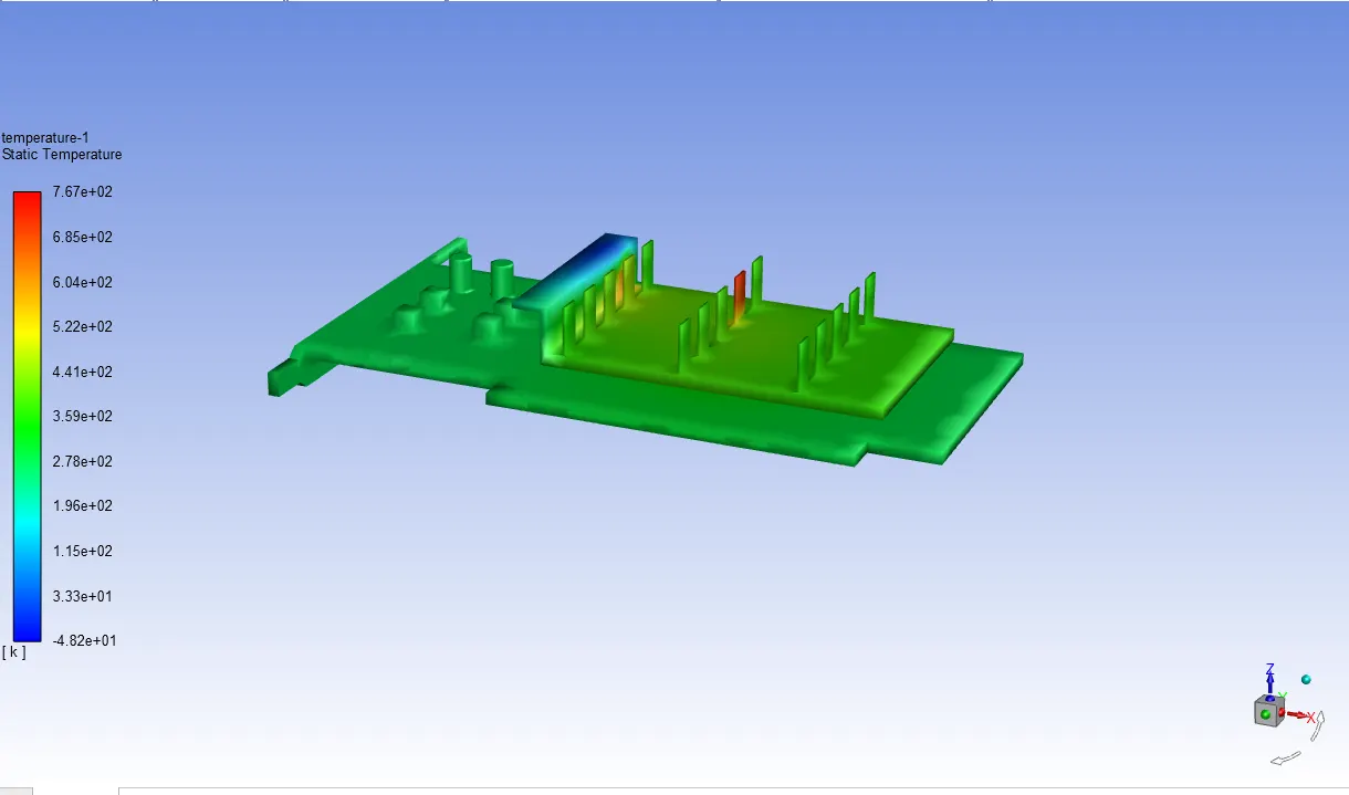
Temperature and hotspots on fins base:
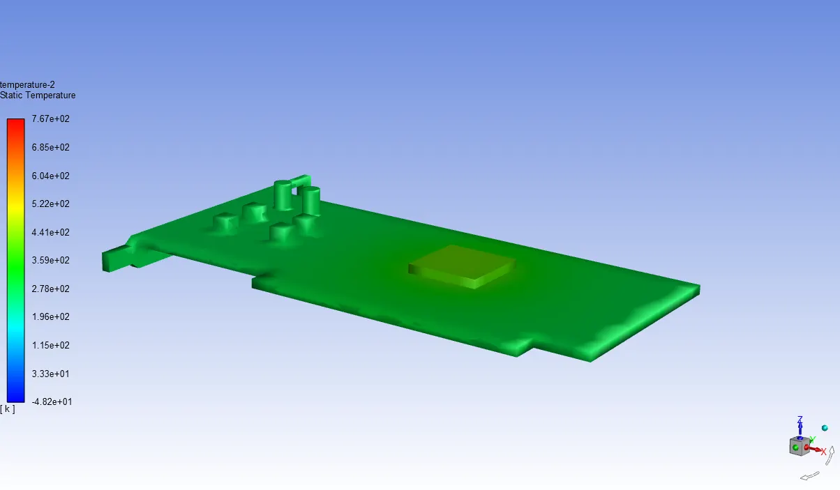
Temperature and hotspots on base with processor:
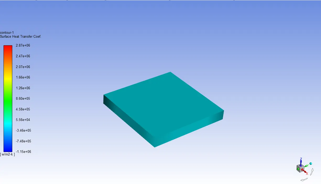
Heat transfer coefficient on processor:
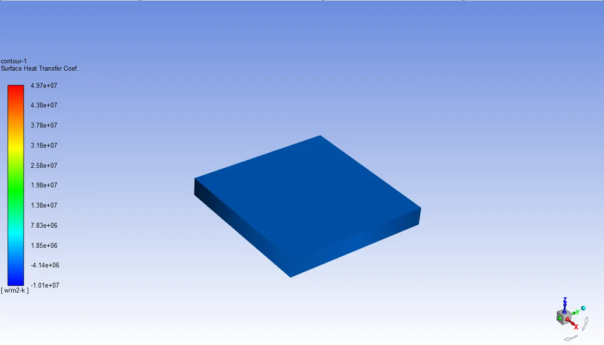
Case 2:
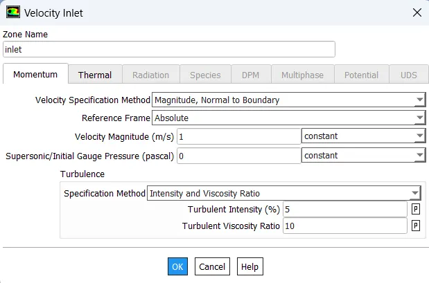
Here we refine our mesh as per the computational resource we have with 2 mm element size and perform the analysis with inlet velocity of 1m/s below are the result generated from it.
Base:
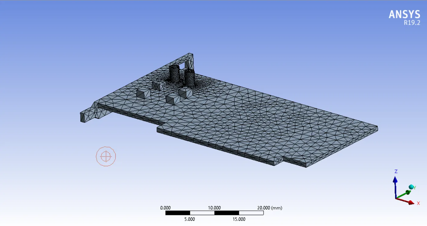
Processor:
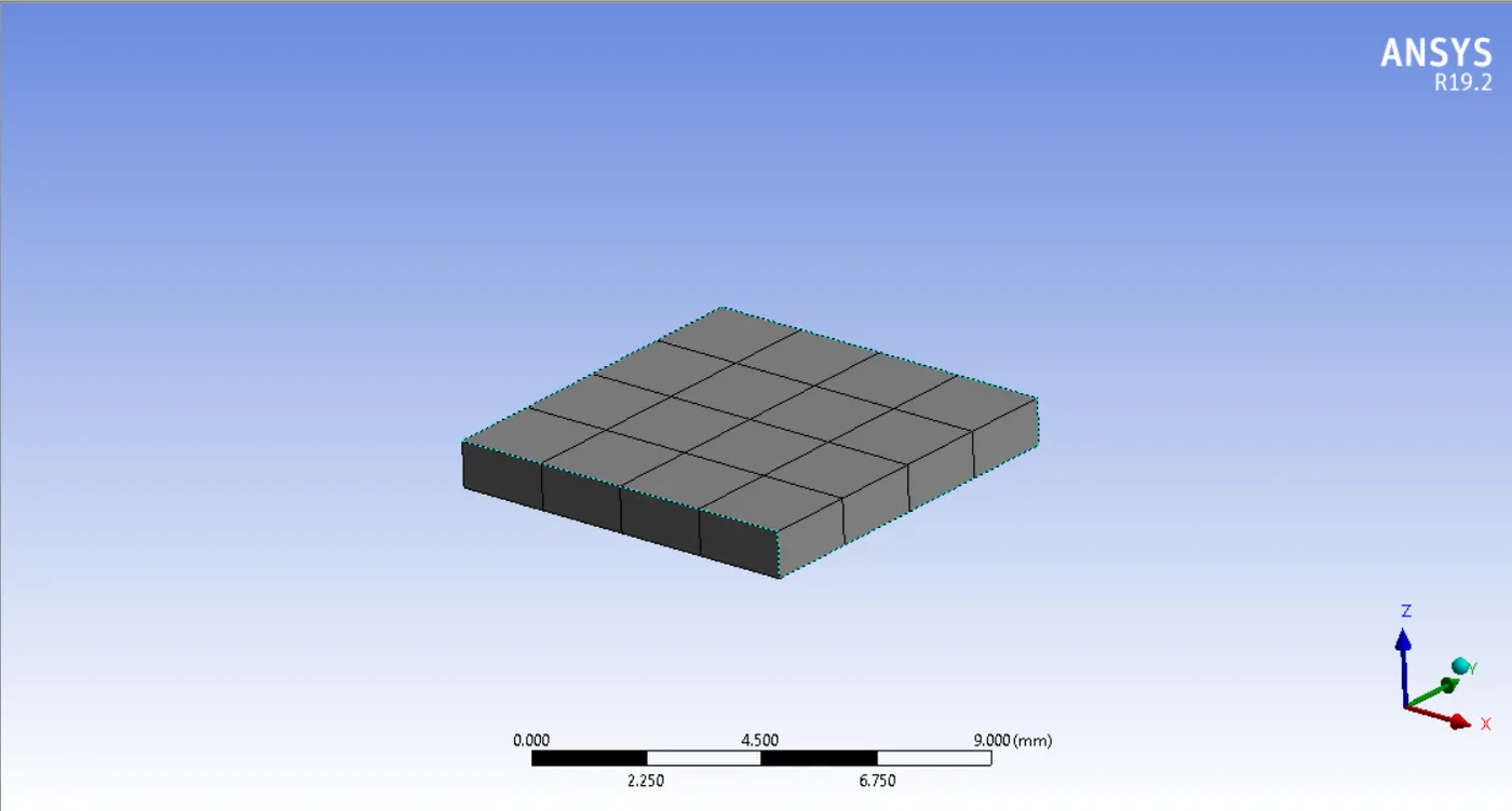
Fins base:
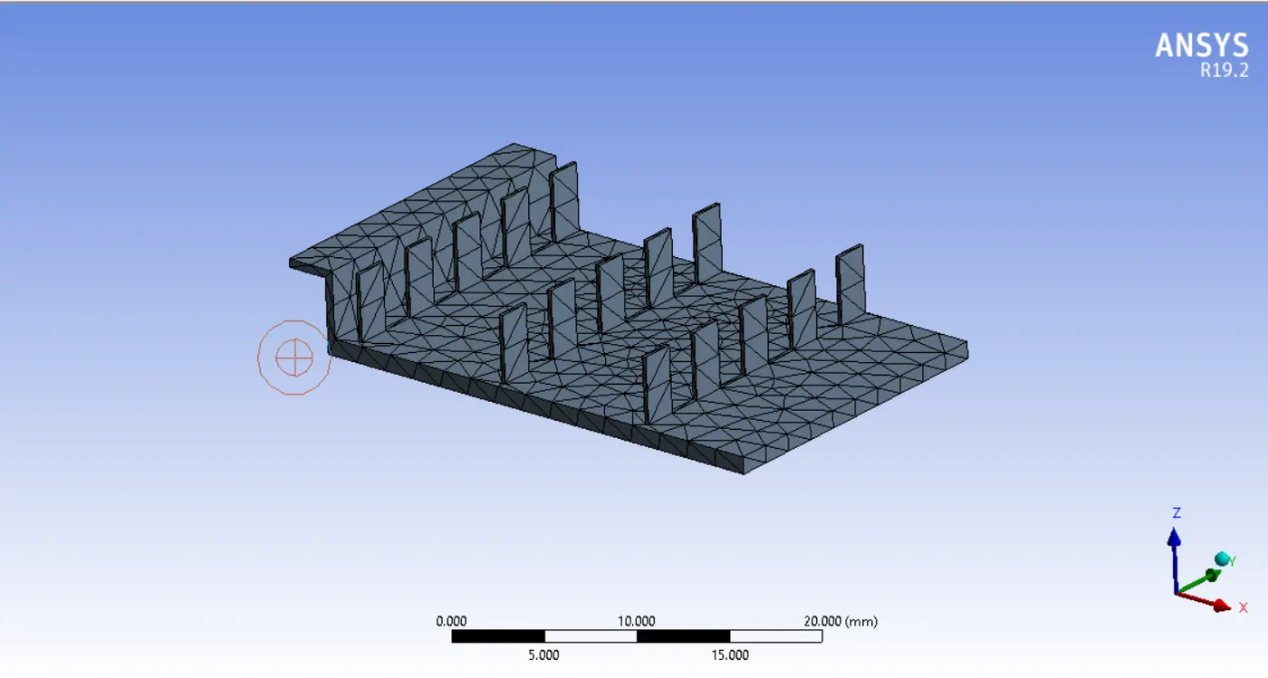
Enclosure:
Residual graph:
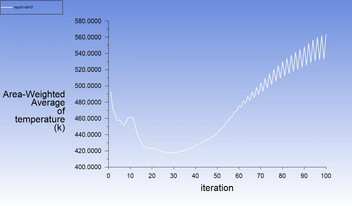
Area weighted average of temperature on processor:
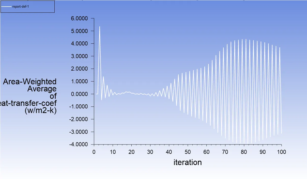
Area weighted average Heat transfer coefficient on processor:
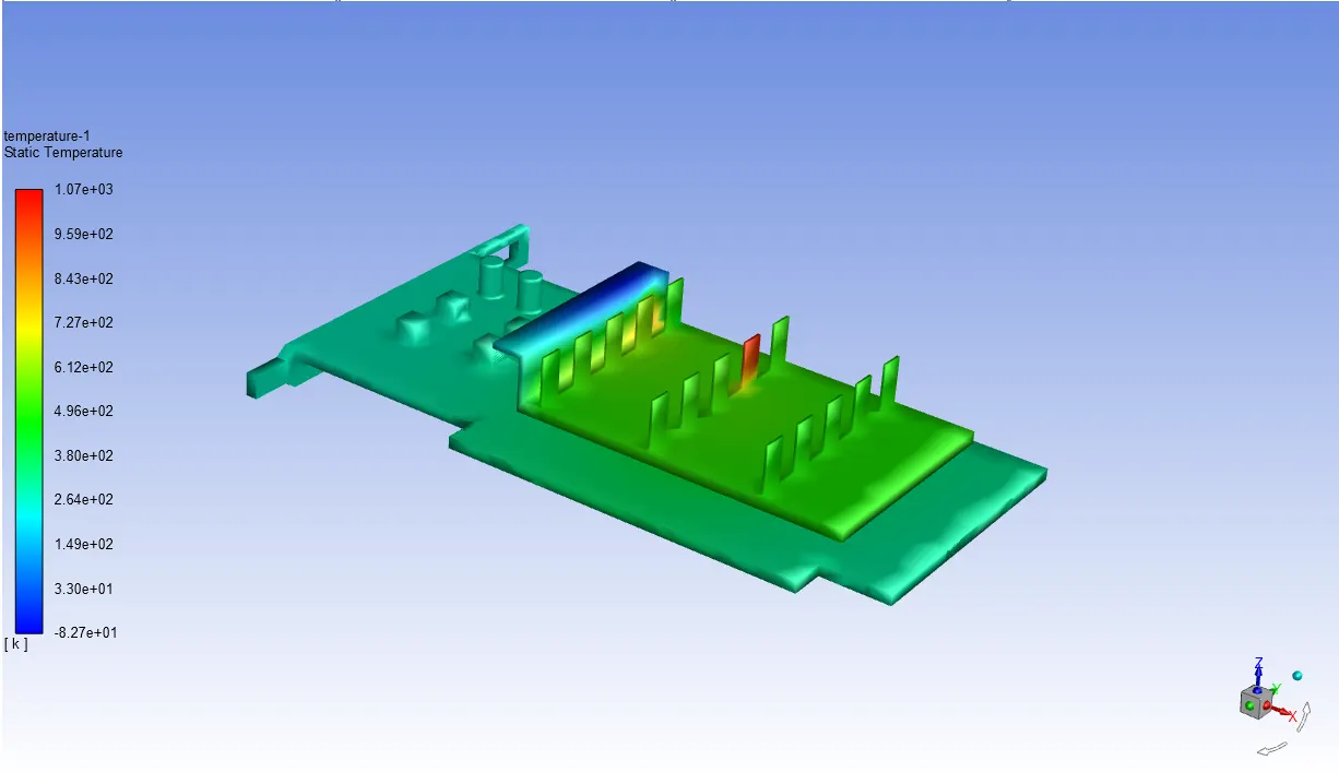
Temperature and hotspots on fins base:
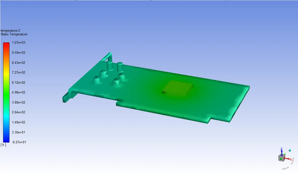
Temperature and hotspots on base with processor:
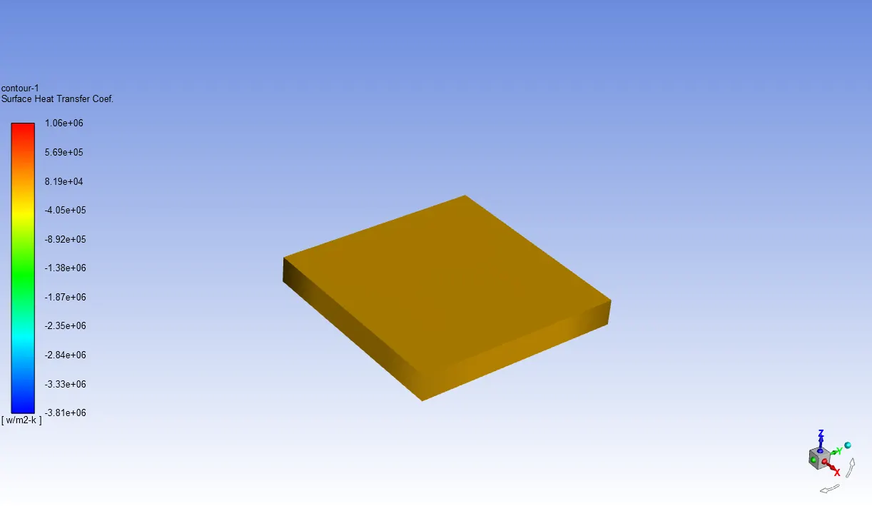
Heat transfer coefficient on processor:
Case 3:
Here we provide the inlet velocity 5m/s below is the figure of inlet boundaries condition and results.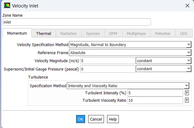
Residual graph:
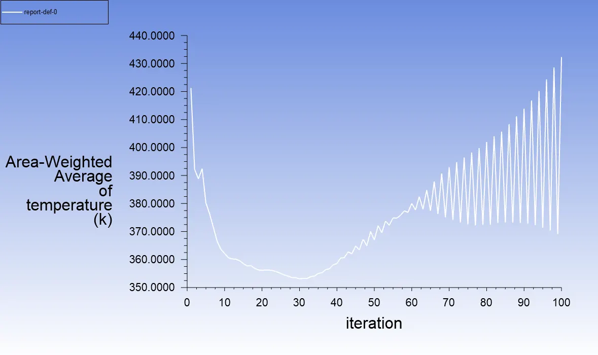
Area weighted average of temperature on processor:
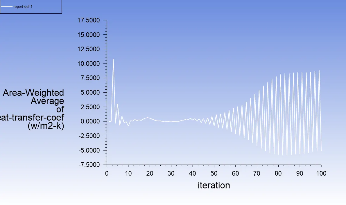
Area weighted average Heat transfer coefficient on processor:
Temperature and hotspots on fins base:
Temperature and hotspots on base with processor:
Heat transfer coefficient on processor:
Conclusion:
This CHT analysis on graphic card chip is taken on ANSYS 19.2 fluent. In this analysis we learn about material input heat flux, heat transfer coefficient and temperature difference.
Below is the result table of analysis with respect to heat transfer coefficient and maximum temperature
|
No. of case |
Inlet velocity in m/s |
Processor temperature in kelvin |
Processor heat transfer coefficient (w/m2-k) |
|
Case 1 |
2 |
566.76628 |
-1511.9045 |
|
Case 2 |
1 |
563.56608 |
-3.1397469 |
|
Case 5 |
5 |
432.2884 |
-5.0918345 |