Week 2 Challenge : Surface meshing on a Pressure valve
Week 2 Challenge : Surface meshing on a Pressure valve
Aim:
To clean up the geometry and apply the mesh of length of 5 mm, 3mm and 1mm and perform the CFD meshing.
Objective:
To find out the error and warning in the geometry, clean up the geometry and perfrom the CFD meshing with three different mesh length of 5mm, 3mm and 1mm.
Body of content:
In this report we will going to look how to find the error in geometry how to rectify that error which comes under geometry clean up. After that we will going to perform CFD meshing and give three different mesh length of 5 mm, 3mm and 1mm. And discuss the result generated by them.
1. Identifying the geometry error
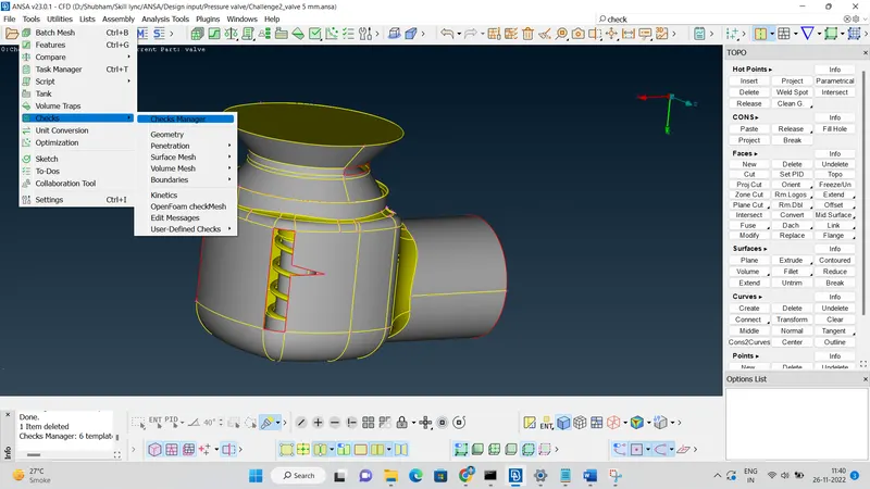
For the geometry cleaning we first have to find out what error our geometry is facing and how to overcome it. To check for the error, go to the geometry check in ANSA v23.0.1 you can find it in tools inside tools to the checks and then click on check manger. As shown in below figure.
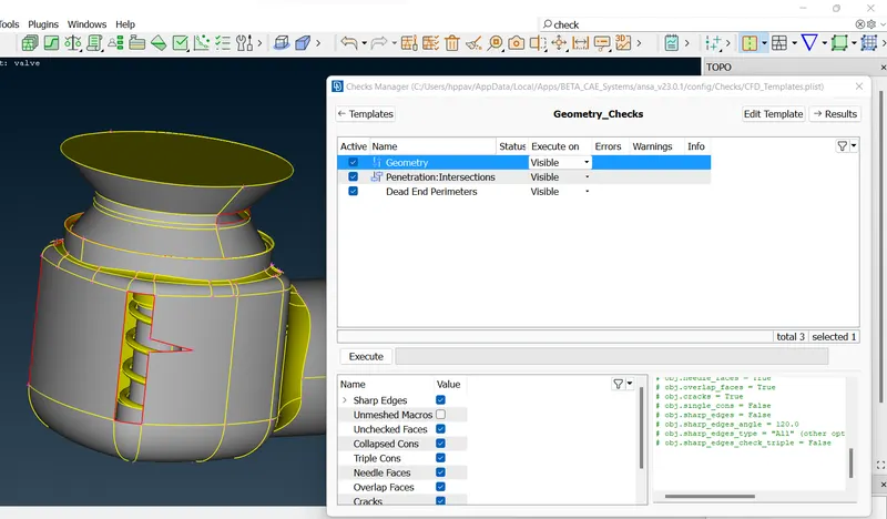
From there you transfer to the window where you can see the error occurred on your geometry parameters and your geometry intersection. As shown in below figure.
Select geometry and click on execute after compiling geometry data it will show you the error on geometry to see the error double click on your geometry. As shown in below figure.
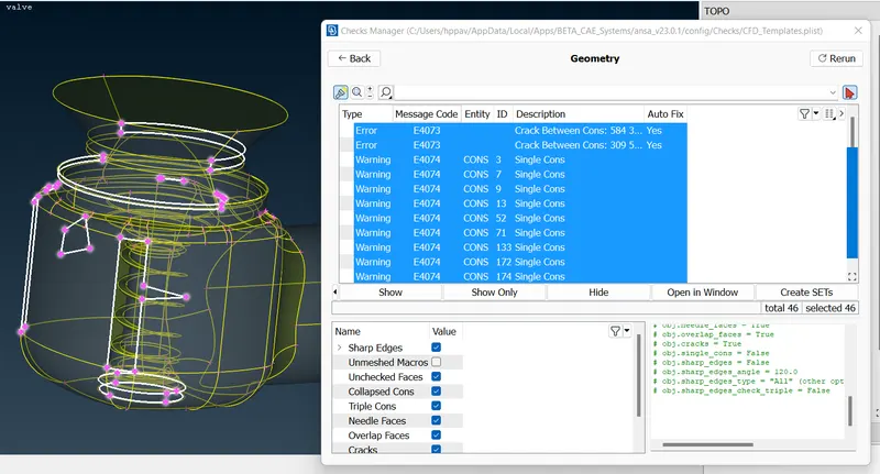
To see the error in your geometry, select all the error and warning and switch to wireframe mode you can see the cons that have error and that error have to be removed for the geometry cleanup.
Now for the other checks like geometry intersection we will using the same procedure to find out the error that we use in geometry, the intersection error tells you whether the two geometry is intersecting to each other or not. Below is the figure shows the error generated by intersecting.
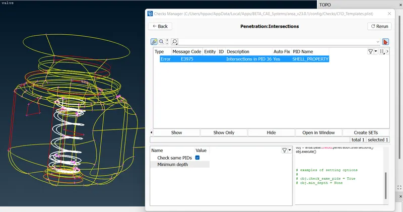
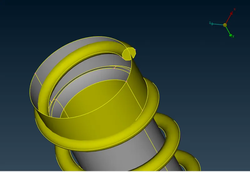
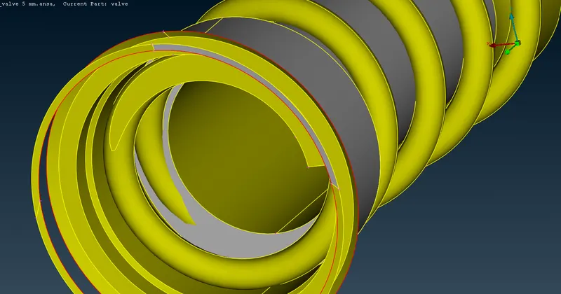
It shows the error in somewhere inside the geometry of valve, below is the figure showing that what happen, one can see that spring is intersecting with the face of shaft. Which is problematic for meshing purpose.
2. Cleaning the geometry
Now we identify the error its time to clean up the geometry, what we will going to do we will one by one go through each error and solve them.
As shown below figure according to geometry check it have red cons so in case to avoid it, we have performed some face operation.
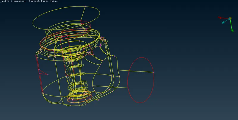
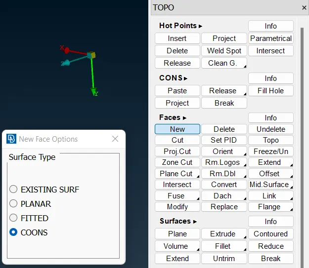
Let takes the circular part to clen that part go to the topo from there find faces and open it, after opening the faces option its shows different operation for face generation as shown in below figure.
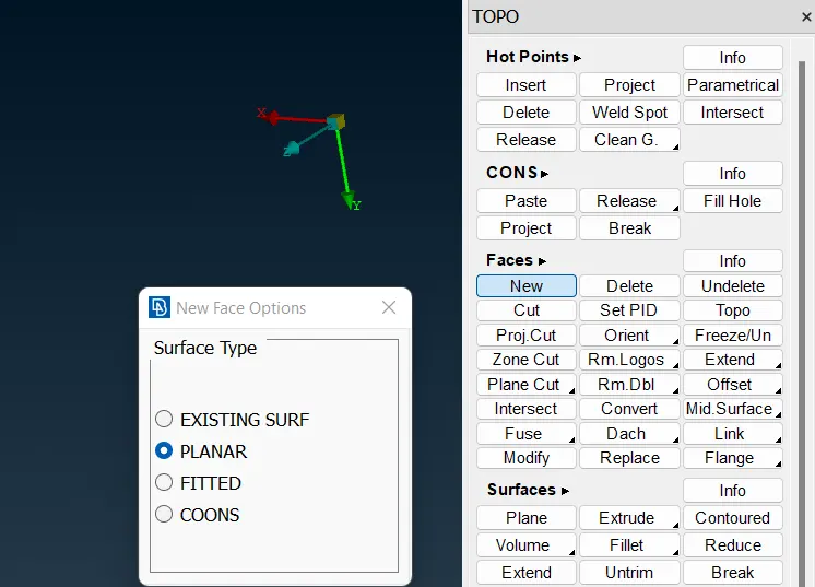
For this geometry cleanup we will going to use planer method. After applying that your geometry going to look like this.
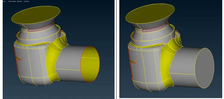
One can see the difference between the two the first one is the error in geometry i.e., red cons and the other one is after geometry cleanup.
Now going to the next geometry cleanup, as shown in below figure one can see that the face of head of valve is missing. Which is shown in red cons.
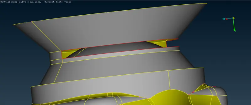
So, to generate the face we will going to do coons command as shown below figure.
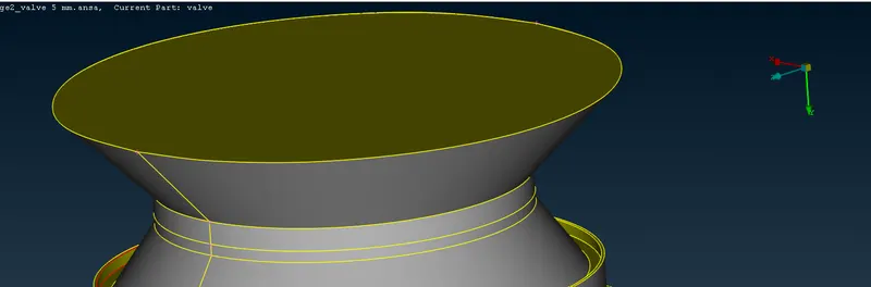
After completing the command your design will going to look like below figure.
Now going to the next error as shown below figure, it has missing face that why the red cons is showing.
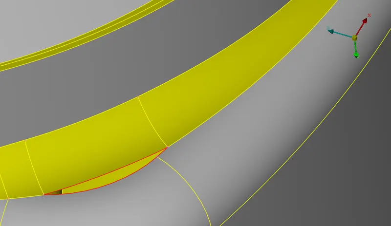
For these we will going to use fitted command, which will help to create a face on it. As shown in below figure.
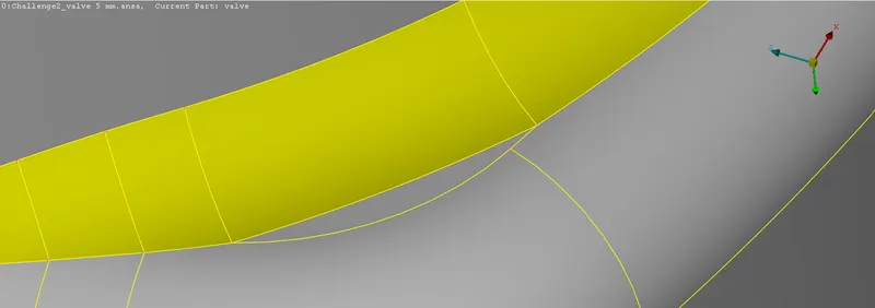
Now moving to the next geometry error, as shown in below figure. The red cons indicate in below figure is its face is missing.
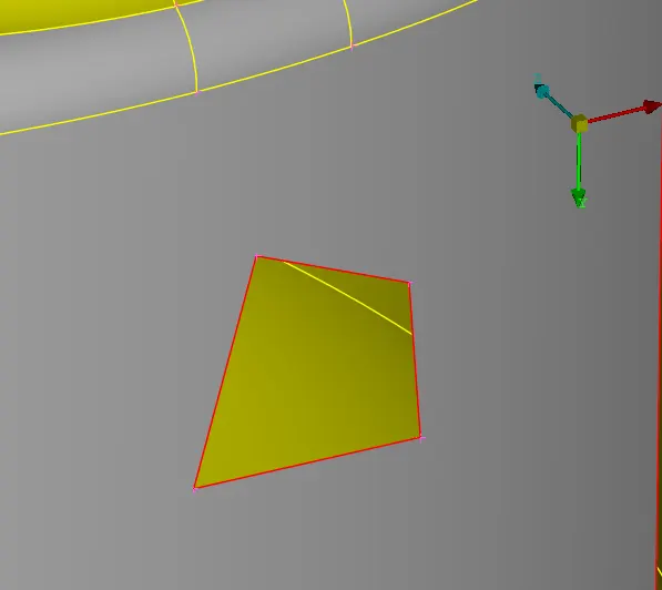
In this case we will be using cons command to fill the holes to access that command go to the cons and selected hole fill. As shown in below figure.
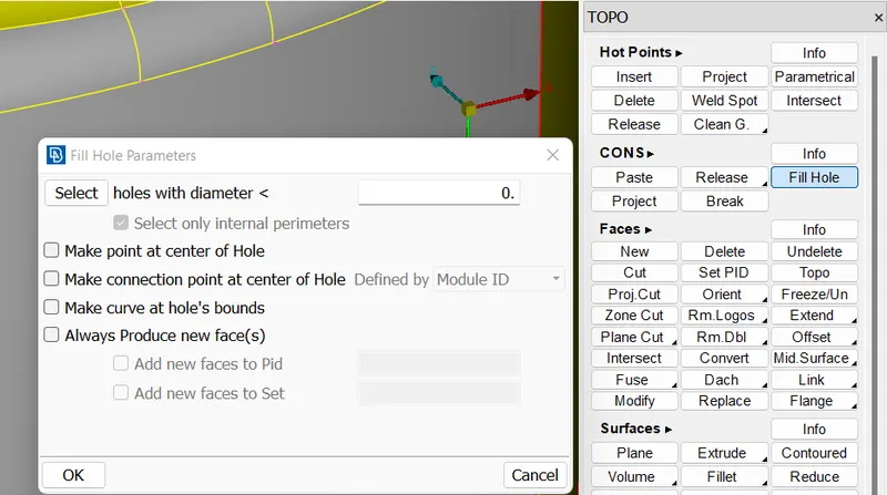
The fill holes command gives as better result as shown in below figure.
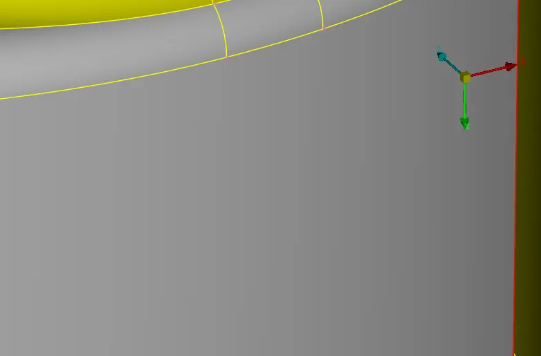
As one can see that it fills the hole which is on the plane.
Now going to the next geometrical error that s on the shaft as shown in below figure.
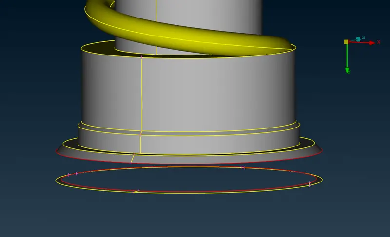
For this part we will going to use the cons option and divide geometry into to i.e., we will first generate half face on and then other half.
As shown in below figure we have selected one half of the cons point and generate face in them.
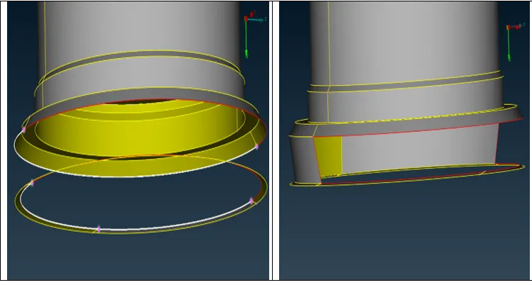
Now, we again go for cons and generate the full face on the body, as shown in below figure
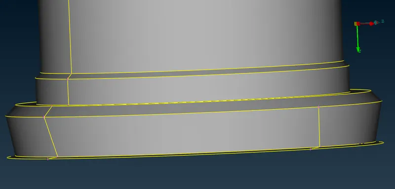
Now go for wire frame mode and find for any red cons that to be eliminated. As shown in below figure one can notice that there is no red cons.
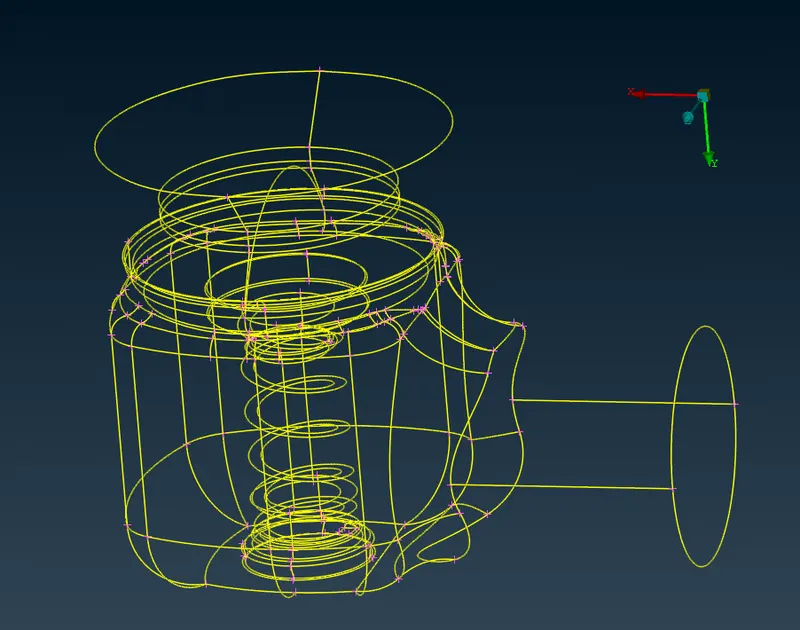
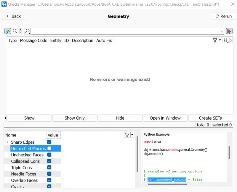
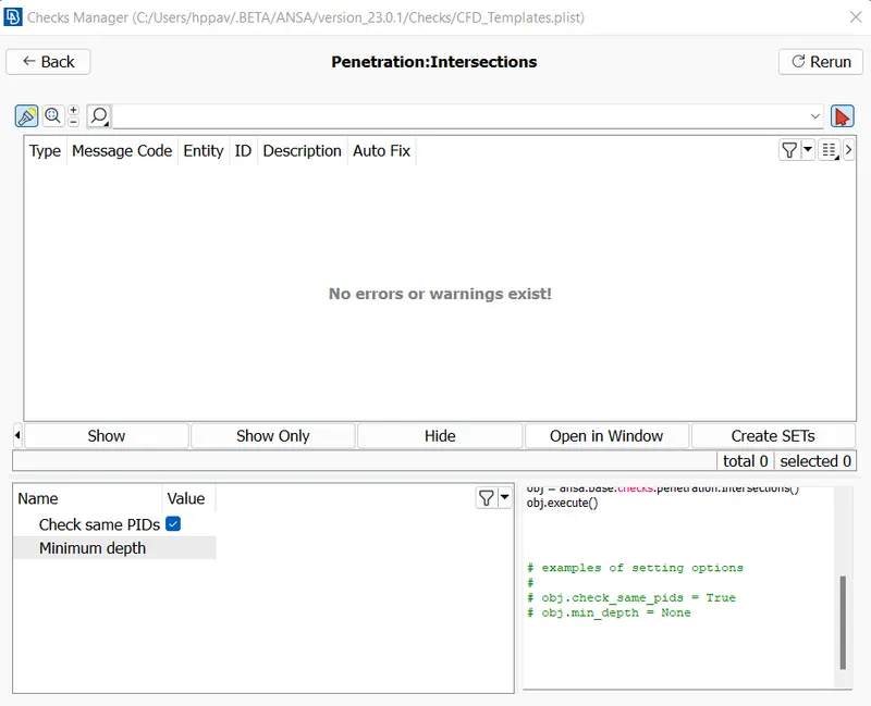
But for better result again do the geometry check, as shown in figure all the errors and warning are nullified.
3. Intersection geometry
As discuss intersection geometry is nothing but the two-component interesting each other. As shown in figure.
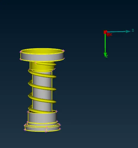
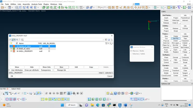
Before performing function for better understanding assign the PID for this two. To perform that function, select not command with PID region as shown in figure it will help to hide one of the components. And then select the other component and give the PID as shown in below figure.
Now for the clean up this geometry we will go with intersection command, so go to the faces and intersect and give the required condition as shown below figure.
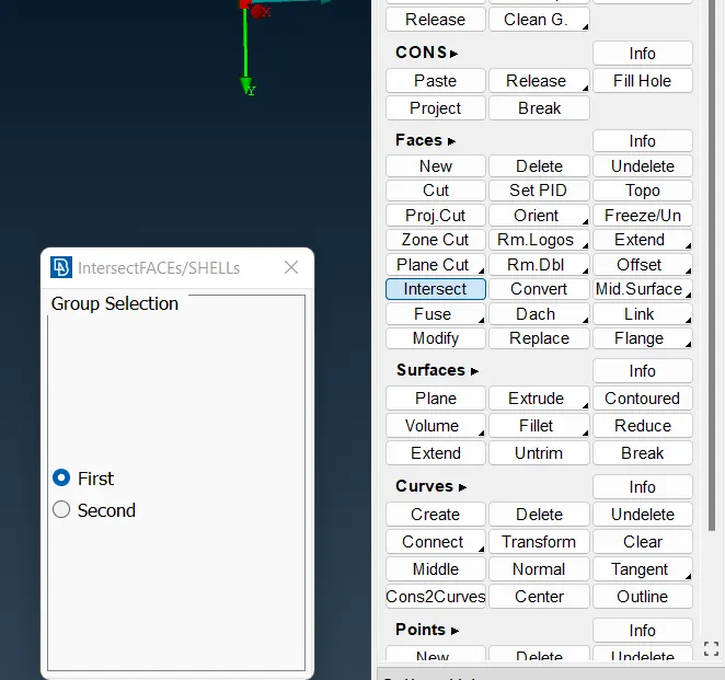
Now enable the PID option and for first group select the shaft of valve and for second select the components. Then after selecting the components click middle click. After that you get your error solved for intersecting geometry as shown in below.
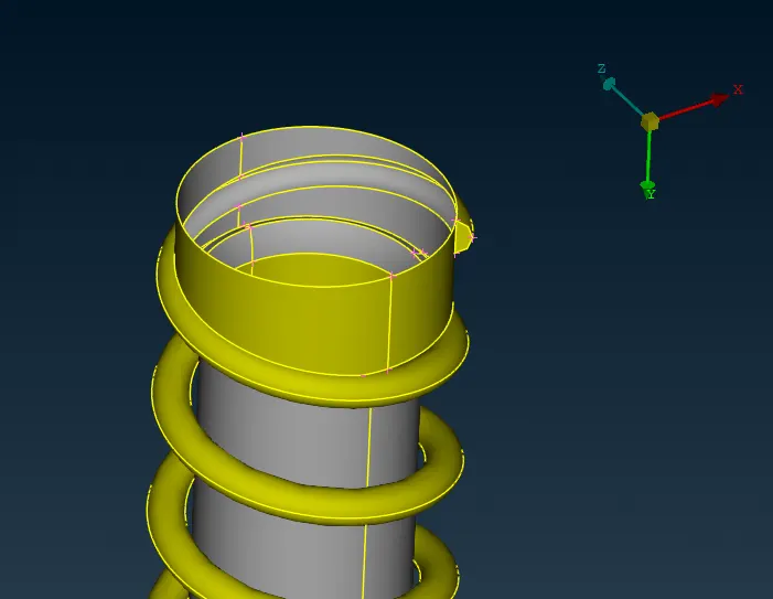
It no longer has another component inside it. for confirm result again go for geometry check as shown below.
4. CFD meshing with three different.
Now we are going to perform CFD meshing on our geometry with three different types mesh length which are 5 mm, 2mm and 1mm. And then compare the result in conclusion.
4.1 CFD meshing with mesh length of 5mm.
We are going to perform 5 mm mesh length CFD meshing, so for that go to mesh topology find perimeters and click on length, after that length perimeter windows will open asking perimeters and macros as shown on below figure. Assign 5mm value in both perimeter and macros respectively.
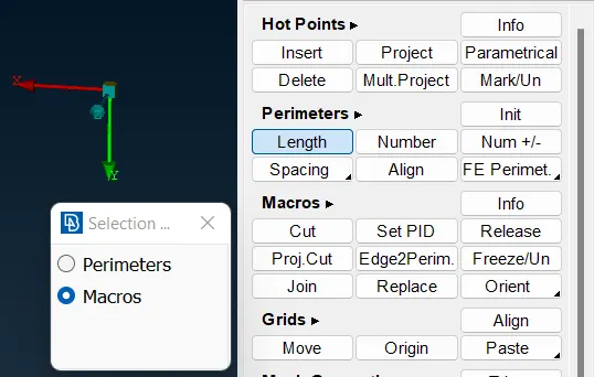
Now go to the mesh generation in mesh topology and find CFD in that CFD go for visible and you will able to see mesh on your valve body. As shown in below figure.
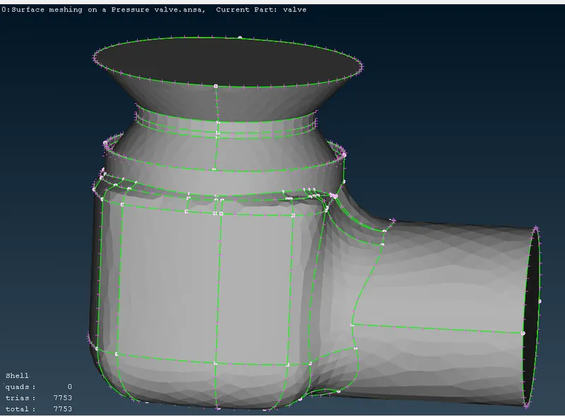
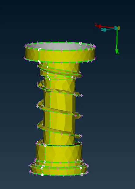
The same quality of mesh occurred on both spring and shaft, as shown in below figure.
4.2 CFD meshing with mesh length of 3mm.
Now we are going to perform the mesh for 3mm mesh length everything is same as we perform for CFD meshing, but now we will change the mesh length to 3mm. the mesh quality by 3mm mesh length is shown below.
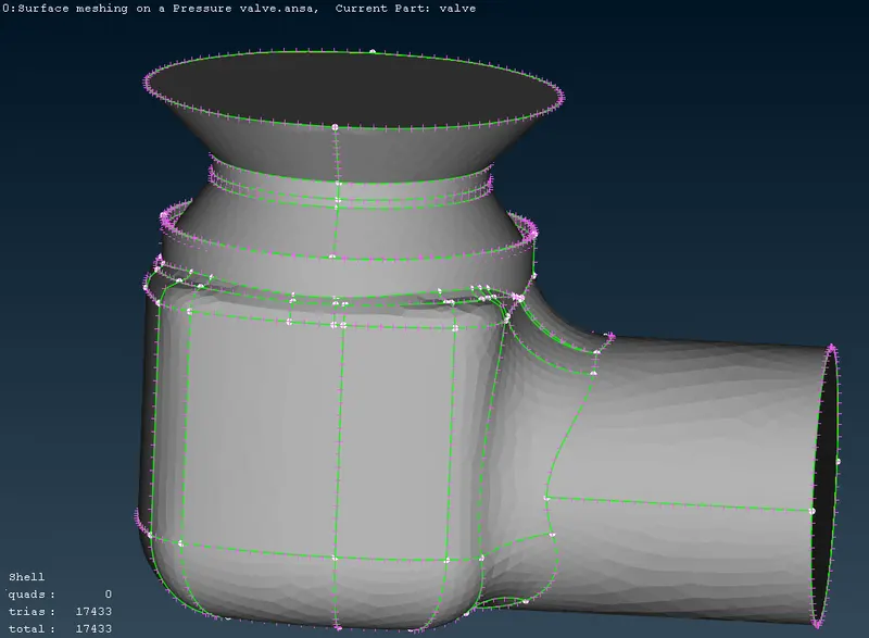
In 3mm mesh length the element produce is around 17433
4.3 CFD meshing with mesh length of 1mm.
Now we are going to perform CFD with 1mm mesh length and see what number of elements we get. As the procedure is same as discuss earlier. Below is the figure of mesh generated by 1mm mesh length.
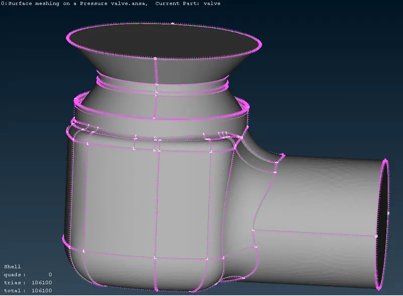
The element obtain by 1mm mesh length is around 106100.
Conclusion:
In this report we discuss how to clean geometry in ANSA v23.0.1 with the help of different topology tools and how to define intersecting error.
We have performed CFD meshing with three different meshing size 5mm, 3mm, 2mm respectively.
We have noticed when we decrease the mesh size length the number of element increase. Also, the mesh we get is finer in decreasing the number of length size. But for the computational resources it took long time to generate.
In this report we learn how to perform geometry check and how to clean it and what happen in decreasing the mesh length