Week 6 - CHT Analysis on a Graphics card
Aim:
(i)To perform a steady-state Conjugate Heat Transer analysis on the graphics card for three different velocities from 1m/s to 5 m/s
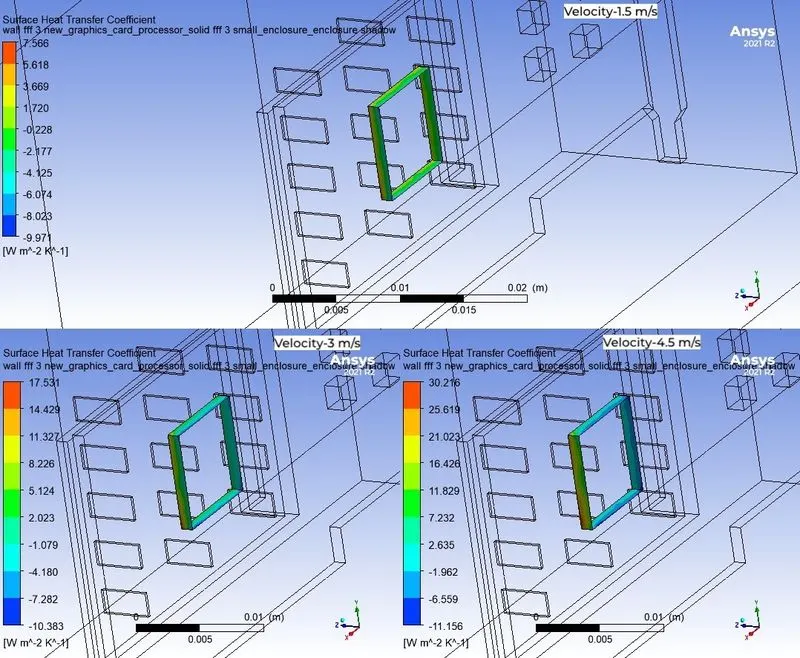
(ii)To determine the maximum heat transfer coefficient and temperature attained by the Processor for varying velocities
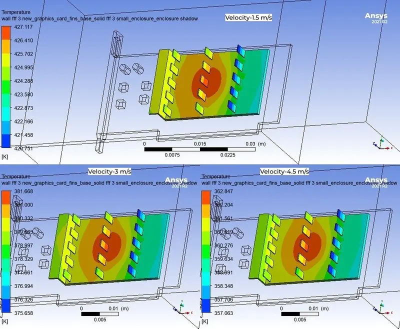
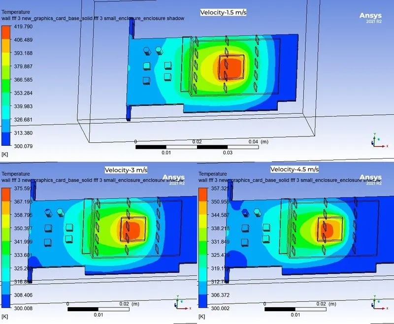
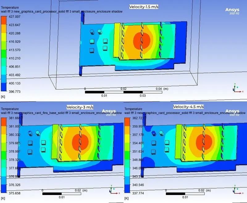
(iii)To identify the hotspots on the model
Introduction:
A graphics card is a computer extension card that generates a feed of graphics output to a display device such as monitor.Graphics cards are sometimes called discrete (or) dedicated graphics cards to emphasize their distinction to integrated graphics processor on the motherboard or the CPU.
The GPU can be used for additional processing,which reduces the load from the CPU.Most graphic cards are not limited to simple display output.Additionally,computing platforms such as OpenCL and CUDA allow using graphics cards for general-purpose computing.Applications of General-purpose computing on graphics cards include AI training,Cryptocurrency mining and molecular simulation. Gpus are mostly used to reduce a loads on CPU on the graphics processing tasks such as video editing,3D Rendering,gaming process.Due to these applications, utilisation of GPUs in various industries are Healthcare,Robotics,Game Development,Consumer Internet,Energy,Financial Services,Manufacturing etc..,
Parts of graphics cards are mounted on the printed PCB board which is made up of core material-fiberglass (or) ceramics,glass,wovenglass,glass fiber would be added to PTFE (or)copper clad laminates(or) Aluminium,copper for connecting components,solidermask-glass epoxy (or)photoimagineable solder mask material (polymer) (or) Dry film photo solder mask material (epoxy).Solder mask will have contact with surroundings.(i) GPUs are silicon layered with tantalum and palladium transistors and capacitors.(ii)Heat Sinks are two types active and passive.active heat sinks need the presence of the fan or liquid cooled arrangement and passive heat sinks works in the absence of fan (or) cooling arrangements.Heat sinks made up of two materials they are copper and aluminium.selection of these materials based upon the thermal conductivity,values of aluminium and copper are 205 and 385 W/mk.Diamond and silver has higher thermal conductivty compared to aluminium and copper but they are very expensive.(iii)The video BIOS or firmware contains a minimal program for the initial set up and control of the graphics card. It may contain information on the memory and memory timing, operating speeds and voltages of the graphics processor, and other details which can sometimes be changed.polysilicon material is used to made a video bios.(iv) VRAM manufactured use capacitors containing electrodes made of doped silicon or polysilicon and dielectric films of silicon dioxide and/or silicon nitride.(V)The RAMDAC, or random-access-memory digital-to-analog converter, converts digital signals to analog signals for use by a computer display that uses analog inputs (such a graphic card consists of VGA interface)(vi)output interfaces are used to connect displays (vii)graphic card interface- gold fingers are manufactured using “hard gold” (electroplated gold), Au thickness 0.8 – 2µm on the PCB’s (viii)Thermal silica gel is used inbetween processor and heat sink
Electronic circuits are composed of components such as resistors, capacitors, inductors, transformers, semiconductors, integrated circuits (ICs), etc. All these components are responsible for the production of heat in electronic circuits.
GPU is an integrated circuit .An integrated circuit (IC), sometimes called a chip, microchip or microelectronic circuit, is a semiconductor wafer on which thousands or millions of tiny resistors, capacitors, diodes and transistors are fabricated.it is smaller and more complex,power densities are increasing and may consits a lot of capacitors will result in much heat generation.
Vram also an Integrated circuit which consists a lot of capacitor will cause a heat.on basic graphic cards does not have a temperature sensor on VRAM and VRAM has a optimal temperature greater than optimal temperature on GPU.GPU temperature reaches greater than optimal temperature then thermal throttling will reduces a peformance based on that temperature wont increase.A cooling arrangment will helps to rectify the temperature.
A Graphic card will be significant in lot of industries.Due to that,manufacturer should be cautious for not happening thermal throttling to avoid a peformance reduction.To handle this problem need a better cooling arrangement.In a present study, Passive heat sink how will help to cooldown the processor
Our study suggests a two possible modes of heat transfer.They are (i)Conduction on the heat sink material from processor (ii)Convection of heat from heat sink material to the surroundings.Heat Transfer through convection works based on External flow.(iii)Radiation is neglible due to emissivity low in the preferred heat sink material.
Conjugate Heat Transfer:
Heat is a form of energy that can be transferred from one system to another system as a result of temperature difference with the help of heat transfer mechanisms.Heat transfer mechanisms are conduction,convection and radiation.Conduction is the transfer of energy from the more energetic particles of a substance to the adjacent less energetic ones as a result of interaction between the particles.conduction can take place in solids,liquids or gases.In gases and liquids,conduction is due to the collisions and diffusion of molecules during their random motion.In solids,it is due to the combination of vibrations of molecules in lattice and energy transport by free electrons.Convection is the transfer of energy between a solid surface and the adjacent liquid or gas that is in motion and it involves the combined effects of conduction and fluid motion.The faster the fluid motion, the greater the convection heat transfer.In absence of any bulk fluid motion,heat transfer between a solid surface and the adjacent fluid is by pure conduction.Both phenomena plays a vital role in the boundary layer development.Radiation is the energy emitted by the matter in the form of electro magnetic waves as a result of the changes in the electronic configurations of atoms or molecules.Unlike conduction and convection, the transfer of heat by radiation does not require the presence of an intervening medium.Among all heat transfer mechanisms radiation is the fastest energy transfer mechanism.
In the traditional area of convective heat transfer between a solid wall and a fluid flow,the wall conduction resistance is usually neglected, i.e. the wall is assumed to be very thin. In this case it is usual to prescribe either the wall temperature or the wall heat flux, and a considerable amount of research work has been done in order to understand the heat transfer characteristics over a wide range of flow configurations and fluid properties. However, in many real engineering systems the wall conduction resistance cannot be neglected since conduction in the wall is able to significantly affect the fluid flow and the heat transfer characteristics of the fluid in the vicinity of the wall. In order to take account of physical reality, there has been a tendency to move away from considering idealized mathematical problems in which the bounding wall is considered to be infinitesimally thin. Thus, the conduction in the solid wall and the convection in the fluid should be determined simultaneously. This type of convective heat transfer is referred to as a conjugate heat transfer process and it arises due to the finite thickness of the wall.
Applications-CHT has been applied to investigate the response of a thermo couple to a sudden jump in ambient temperature,on Heat Exchangers (cooling applications for mechanical,electrical and electronic components),Heat treatment of metals and alloys ,space vehicle design and Bio systems.
Modelling:
Geometry:
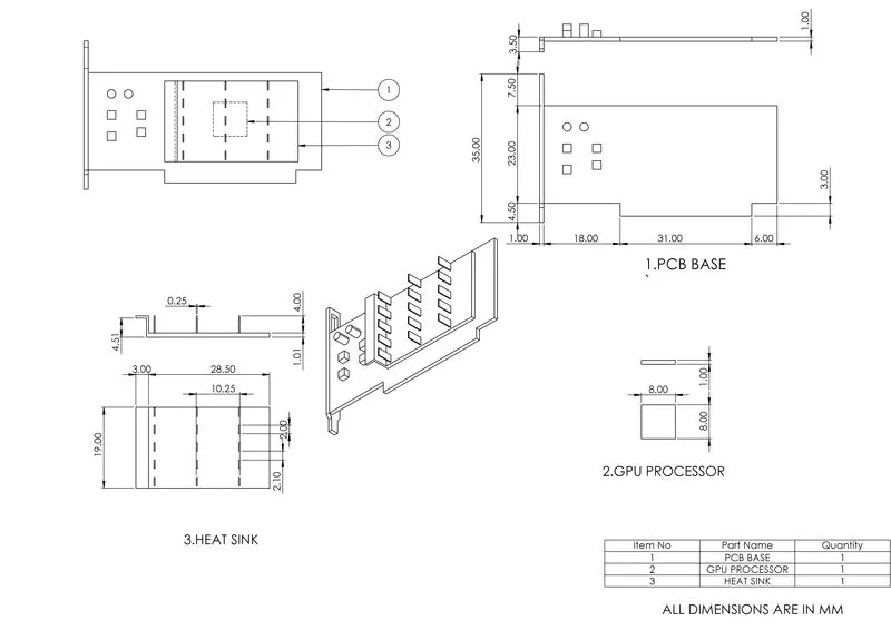
Spaceclaim Software really helps to flow information from one component to other component with the help of share option and enclosure dimensions(LxWxH) are 191x40.5x65 mm.
Enclosures are significant to represent the graphic card placed in a working environment.
Meshing:
Meshing done by applying the different body sizing for various parts of the graphic card even for the base mesh.Reason for applying different body sizing and utilising a woksheet is mesh each and every part of the graphic card.
From base mesh to refined mesh is created for only one case having velocity of 1.5 m/s.
Grid independency test will help to choose the optimal mesh based on change of paramaters (i.e..,Temperature and Surface Heat Transfer coefficient ) from base mesh to refined mesh.
Once simulations are done.checking the temperaturature difference (or) error with next updated mesh.from that which will provides the lowest error will be condition to select the mesh.
|
S.No |
Velocity in m/s |
Global & Refined volume Element Size |
Additional Refining options |
Cell Count |
Averge Temperature in K |
Surface Heat transfer coefficient in W/m^2 K |
Temperature difference (%) |
|
1. |
1.5 |
7 mm |
Body sizing has done to mesh each and every part |
105101 |
411.527 |
637.185 |
3.63 |
|
2. |
1.5 |
7 mm & 5 mm |
Body sizing and inflation layer is included |
245271 |
427.041 |
559.776 |
-1.66 |
|
3. |
1.5 |
7 mm & 4 mm |
Body Sizing,inflation layer and volume Refining has included |
495971 |
420.150 |
594.352 |
Note
- Area weighted average of Surface heat transfer coefficient at the interface (Processor-Fins).
- Volume refining done to achieve the refining around the graphics card.
- Inflation layer would be created based upon the Y+ value of the previous meshes.
On the base mesh,body sizing has been included to mesh the each and every part of the model.while refining to medium size mesh ,drop of global element size from 7 to 5 mm and inflation layer will exceeding the mesh of 5,00,000 elements.For that reason,small Enclosure has been created by observing the base mesh of temperature parameter and sizing features from base mesh has copied and reduced their element sizes.Sane kind of setup used for refined mesh by reducing the global,Volume enclosure,body sizing element size and inflation layer has changed based upon the previous mesh Y+ value.
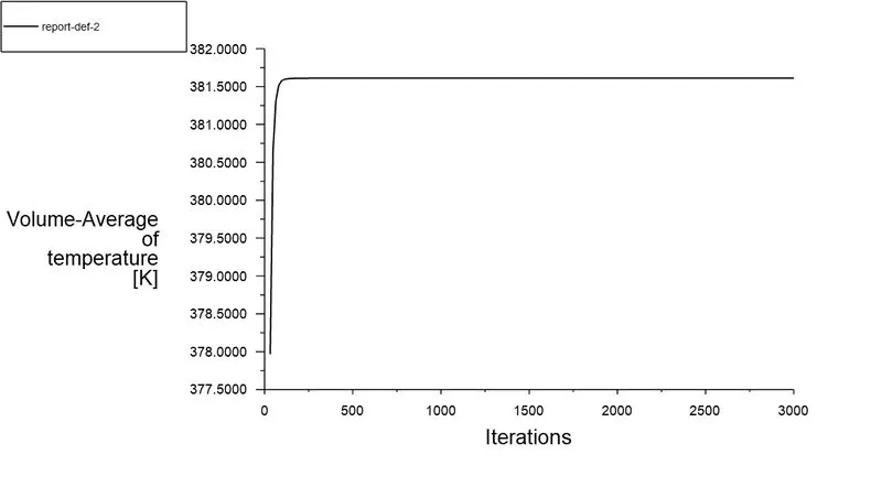
In our study medium size Mesh has been appropriated as the optimum mesh.Using that mesh without changing any setting except the inlet velocity boundary condition as 3,4.5 m/s and ran the simulation
Physics Setup:
- Pressure-Based solver has been selected by assuming as an incompressible flow and velocity formulation is used as absolute because the flow domain is not moving.
- Steady State solver has been used to capture the behaviour after reaching the steady state (or) equilibrium.
- To evaluate the temperature,Energy Equation must be included.
- Considering the viscous model as k-ѠSST model (Assume the graphics card in a working environment. CPU case appears like Square block with smaller vents.so it is an internal flow.turbulent case has a very low reynolds number and solving near the wall is really important because thermal boundary develops and heat transfer takes place at the contact )
- Created a solid Material and air of 300K has dynamic viscosity 0.0000185 Kg /m-s
|
Material Name |
Density in Kg/m^3 |
Specific Heat in J/Kg-K |
Thermal Conductivity in W/m-k |
|
PCB-FR4[1] |
1800 |
1600 |
0.29 |
|
Silicon[1] |
2330 |
705.5 |
153 |
|
Air[2] |
1.177 |
1005 |
0.0261 |
- Assigning the material for the enclosure is air at 300K and air at 300K has assigned to the volume refining enclosure and silicon material assigned to the processor and PCB-FR4 assigned to the PCB-board on the top of that processor is attached.copper assigned to the Fins
- Velocity of air is assigned at the inlet boundary condition and atmospheric pressure is applied to the outlet boundary conditon(zero guage pressure) and temperature is assigned as 300K for both boundary conditions.walls of enclosure assigned as symmetry boundary condition.
- Interface are assigned as wall boundary condition.there are 5 interfaces.
- Hybrid initialisation is used (it solves the laplace eqaution for both pressure and velocity fields) for better estimation.
- Coupled scheme used for Pressure velocity coupling scheme.(It solves pressure and velocity simultaneously).
- Flux type Rhie-chow:Momentum based will be selected automatically for incompressible fluid.
- Spatial discretization Gradient scheme is Least square cell based method(Based on the differentiation formula and matrix equations AX=B and on skewed and distorted meshed accuracy is comparable to guass node based method but it computionally less expensive)
- Spatial discretisation for pressure,Second order scheme is used (Averging the two cell cetered and using the first order taylor expansion)
- Momentum,Turbulent kinetic energy,specific dissipation rate,Energy uses the Second order upwind scheme (based on taylor first order series expansion ,to determine values at cell faces)
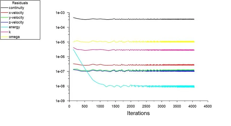
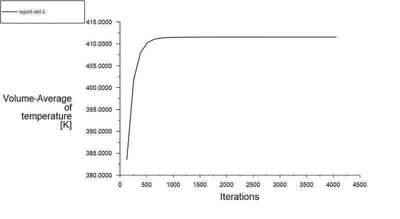
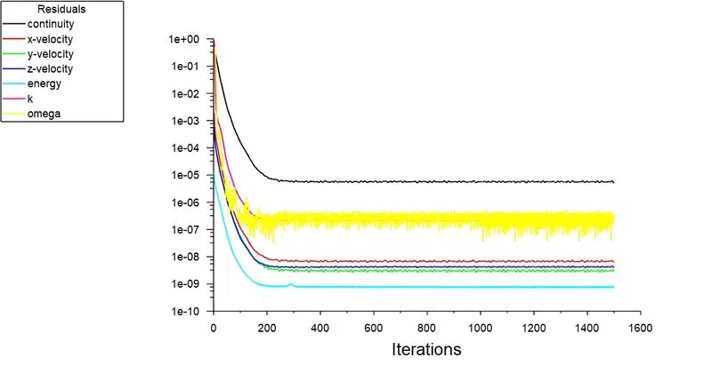
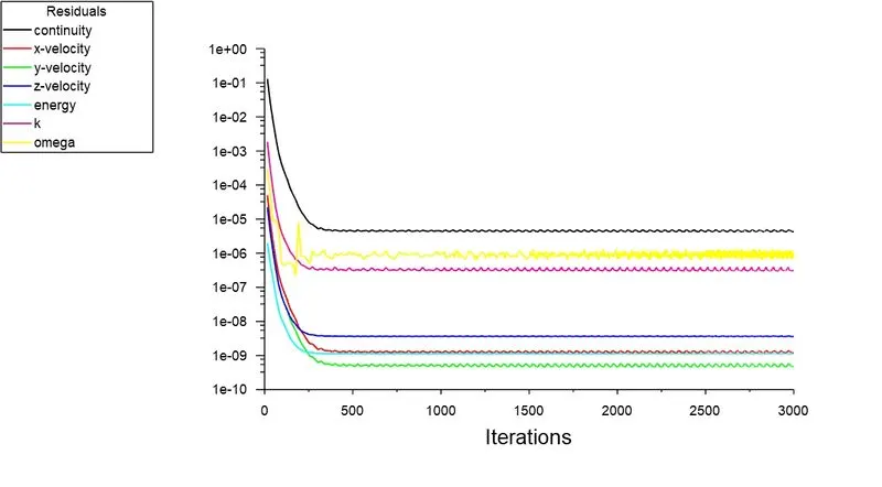
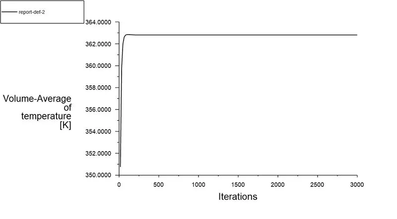
- Created a plots for average temperature at processor,surface heat transfer coefficient at processor and fin interface.and monitored residuals to check the cenvergence of the simulation
Plots:
Velocity -1.5 m/s
- BaseMesh
2.Medium Size Mesh
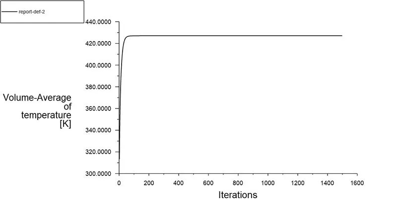
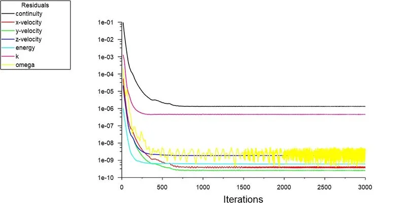
3.Refined Mesh
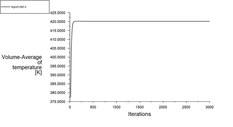
Velocity-3 m/s
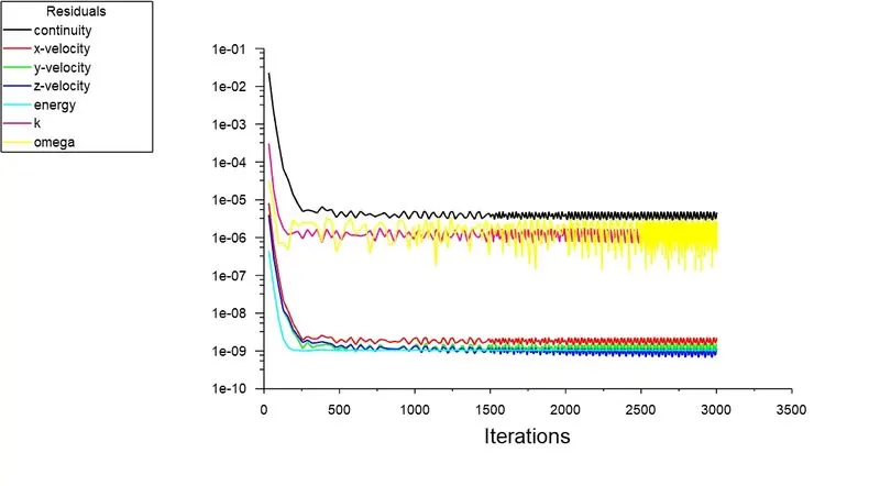
Velocity-4.5 m/s
Attained Max temperature and Surface Heat Transfer coefficient :
For Different Velocities:
temperature attained at the PCB board and processor interface
Temperature attained at Fin-processor Interface:
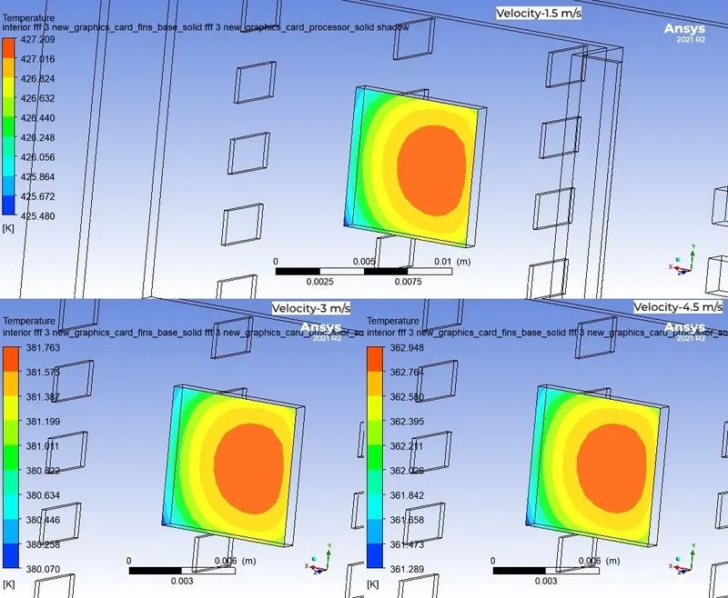
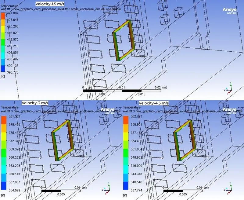
Temperature Attained at Processor-Enclosure Interference
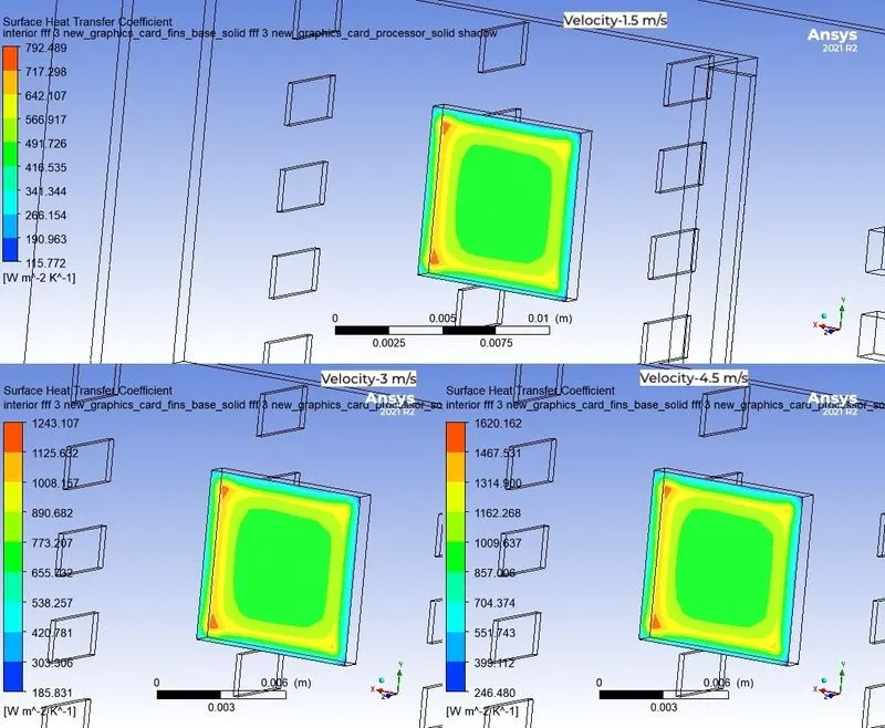
Surface Heat Transfer coefficient at fin-Processor interface
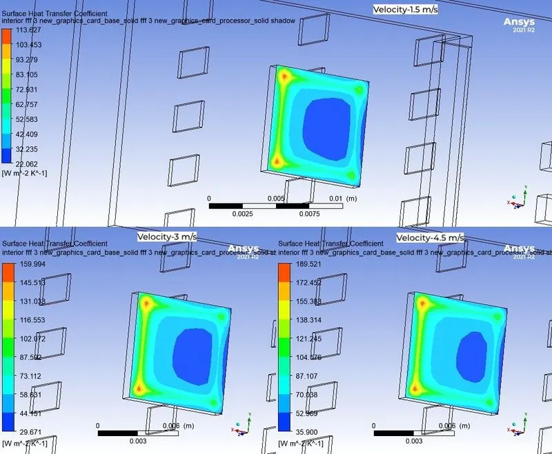
Surface Heat Transfer coefficient at PCB Board-Processor interface
Surface Heat Transfer Coefficient at the processor-Enclosure
Hotspots:
On Fins:
On base:
Graphic card model:
Conclusion:
|
S.No |
Velocity in m/s |
Average Temperature of the processor in K |
Average Surface Heat Transfer Coefficient in W/m^2 K(processor-fin interface) |
Max temperature of the processor in K |
Max Surface Heat Transfer coefficient at the processor interface in W/m^2-K |
|
1. |
1.5 |
427.041 |
559.776 |
427.386 |
792.489 |
|
2. |
3 |
381.610 |
880.216 |
381.943 |
1243.107 |
|
3. |
4.5 |
362.804 |
1150.148 |
363.127 |
1620.162 |
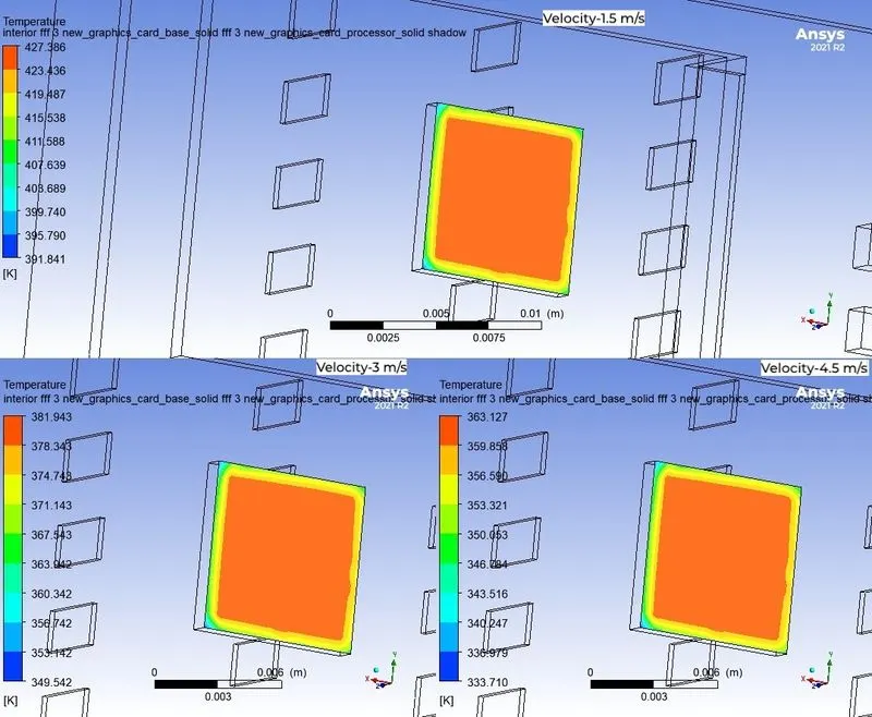
- As the air flow velocity increases over the heatsink and side of the processor will drop the temperature of the processor.(At high Reynolds numbers (in the turbulent regime), there is substantial breaking away of the fluid from the tube wall. This causes significant mixing of the boundary layer and the bulk fluid, enhancing the heat and momentum transfer between the fluid particles.)
- Surface heat transfer coefficient increases as the velocity of the fluid increases.Some theory suggests that Heat Transfer coefficient depends upon the Nature of fluid motion (Laminar or Turbulent flow )
- Thermal resistance (or) Convection Resistance is inversely proportional to the Heat transfer coefficient.The Heatsink comprises of Maximum heat transfer coefficient at the fins present at front where the resistance for rate of heat transfer is so small.
- Creation of inflation layer estimated the thermal effects near the wall (on viscous sub layer).That is the reason of sudden increase on the temperature from base mesh for the medium size mesh
- Due to refinement of the mesh around the inflation layer will drops the temperature by capturing the fluid with more accuracy.
- The maximum temperature would be recorded at the center in width but away from center on length in the flow direction of the processor where covered by the top surface with highly thermal conductivity material and bottom surface with low thermally conductivity material.
- Residual plots and average temperature plot for each and every case is provided to represent that convergence is achieved.
References:
1.A Heat Transfer Textbook:Fifth Edition.,John H Lienhard.
2.Air properties for different temperature https://neutrium.net/properties/properties-of-air
3.Graphics card,https://en.wikipedia.org/wiki/Graphics_card
4.Interface,https://www.multi-circuit-boards.eu/en/pcb-design-aid/pc-pci-boards.html
5.Heat and Mas Transfer,fundamentals and applications,by YUNUS A. ÇENGEL,University of Nevada, Reno and AFSHIN J.GHAJAR ,Oklahoma State University, Stillwate.