Week 6 - CHT Analysis on a Graphics card
Aim and its objective:
- To run the simulation at least three times while altering the velocity from 1 m/sec to 5 m/sec, then talk about the outcomes.
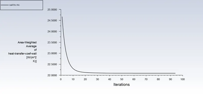
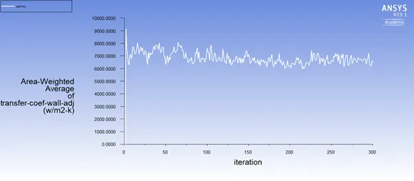
- To find out the processor's maximum temperature and heat transfer coefficient.
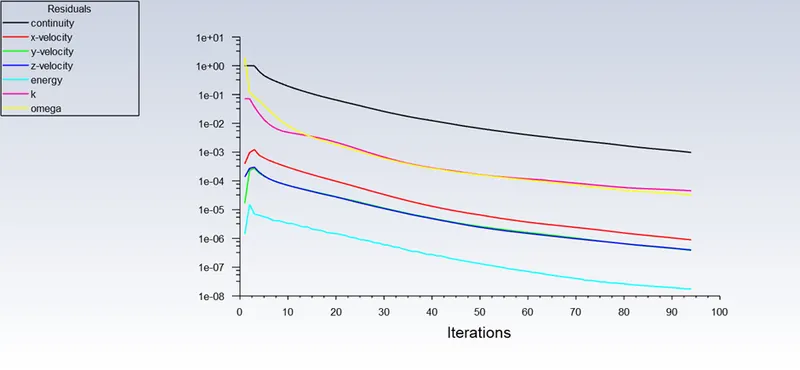
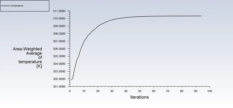
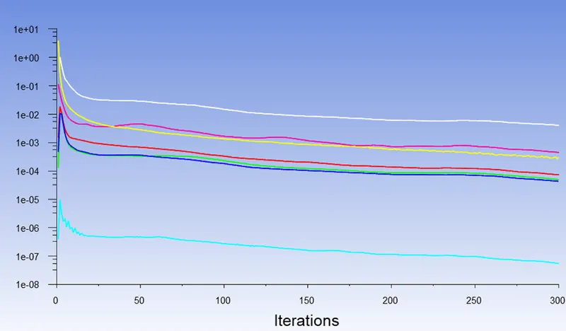
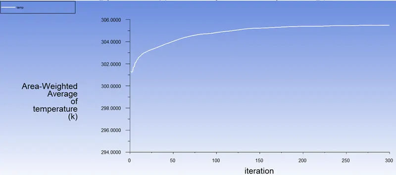
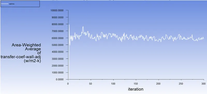
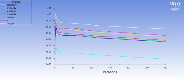
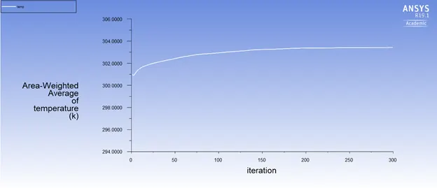
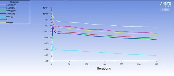
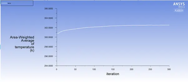
- To provide relevant visuals and charts to demonstrate that the simulation has reached convergence.
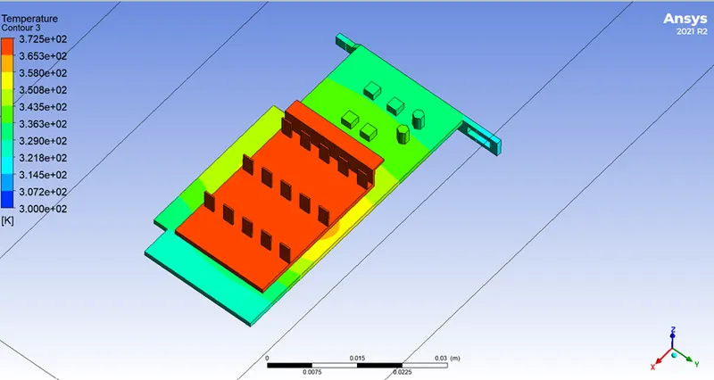
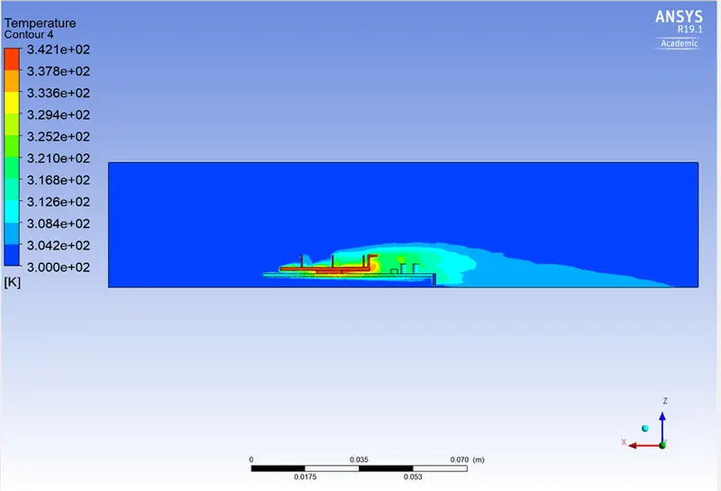
- To determine any model hotspots that may exist.
Introduction
Conjugate Heat Transfer (CHT) analysis
Conjugate Heat Transfer analysis allows for the simulation of heat transfer between solid and fluid domains by exchanging thermal energy at the interfaces between them and transporting via conduction within solids and additionally via convection within fluid domains. Conjugate heat transfer analysis can accurately predict heat transfer by simultaneously solving all the relevant solid and flow field heat transfer processes. Conjugate heat transfer corresponds with the combination of heat transfer in solids and heat transfer in fluids. In solids, conduction often dominates whereas in fluids, convection usually dominates. Conjugate heat transfer is observed in many situations for example conduction through solids, free and forced convection in the gases/fluids, and thermal radiation.
- The three main modes of heat transfer:
‐ Conduction is heat transfer that occurs when a temperature difference exists across a stationary medium.
‐ Convection is the heat transfer between a surface and a moving fluid when there is a temperature difference between the two.
‐ Radiation(thermal radiation) is the emission of energy in the form of electromagnetic waves. In the absence of an intervening medium, there is net heat transfer by radiation between two surfaces at different temperatures.
Importance in practical applications:
- Other Applications of GPUs Besides Gaming Video Editing Video encoding, the process by which video data is prepared and formatted before playing, is supported by modern graphics cards.
- Rendering for 3D graphics.
- Computer learning.
- Bitcoin mining and blockchain technology.
- Recognize how crucial a graphics card is to the development of machine learning. Images are calculated by a computer's graphics card, sometimes referred to as the graphics processing unit (GPU), and then shown on a monitor. It serves as the connection between the calculations made by the processor and the monitor.
Procedure:
Case 1- Baseline setup - Steady case
Pre-processor
Geometry in space claim:
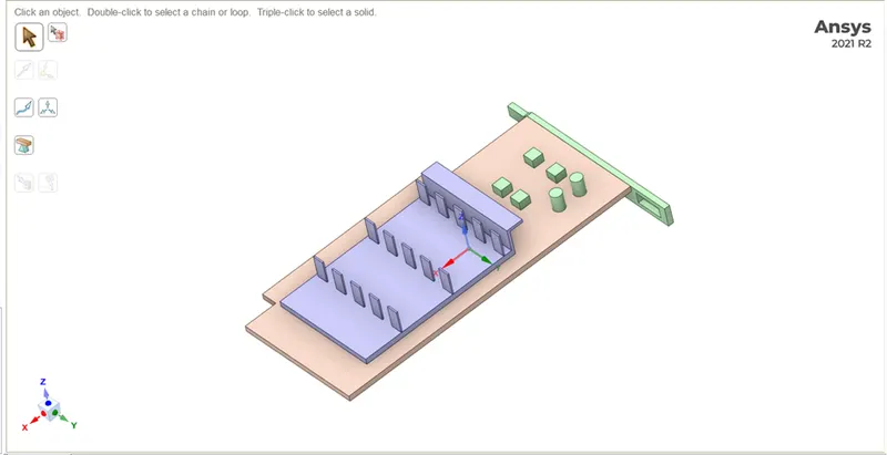
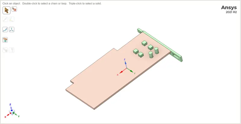
1. Edit the geometry of the downloaded graphics card model inside the enclosure using SpaceClaim.
2. Click on share prep to see any interference-causing edges so that various components can mesh in a conformal manner.
3. Share topology between the various components needs to be enabled so that relevant data may be shared across various mesh zones.
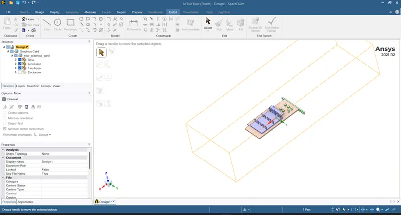
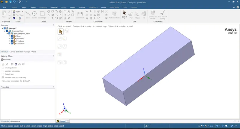
- Shareprep - Most important to do this step in geometry. If it is not done, then there'll be no interfaces where information is shared and mesh will definitely fail. Basically, this step takes care of creating interfaces.
-
Conformal mesh - There would be a face that both solid mesh and fluid mesh will share, which is perfectly interfacing or conforming to the solid mesh.
-
Non-conformal mesh- Actually there'll be a physical gap between two bodies, one vertex should connect with another vertex (not overlap properly). In order to to do that, do share topology in geometry.
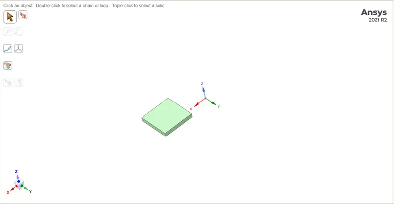
Base:
Processor:
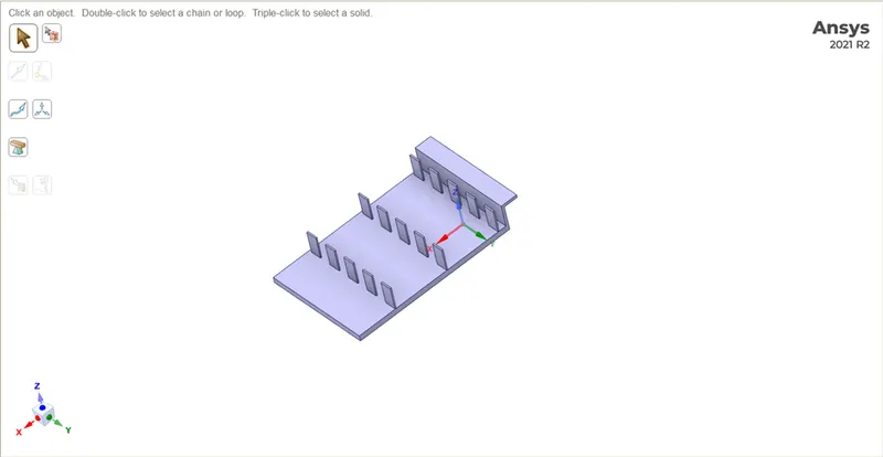
Fins:
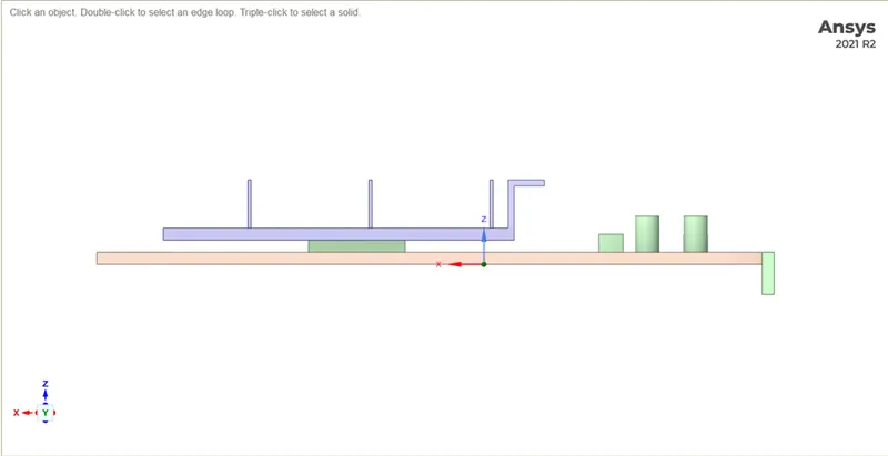
Side view model:
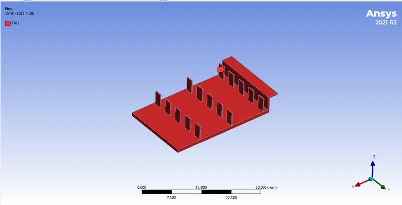
Initial condition (Named selection):
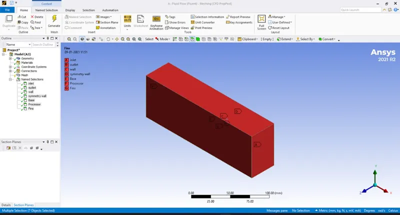
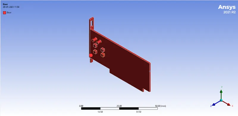
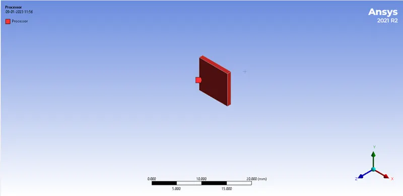
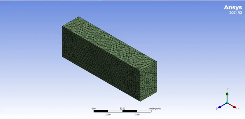
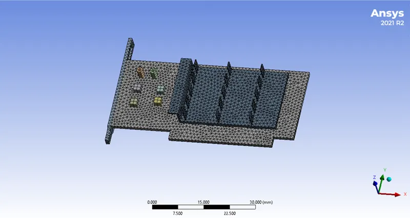
Baseline mesh
Using the Ansys-recommended standard values, the base mesh is produced. We will utilize this mesh to get a preliminary answer that will show us where mesh refinement is necessary.
| Material | Mesh size |
| Base | 1 mm |
| Fin | 1 mm |
| Processor | 1 mm |
| Enclosure | 8 mm |
No of elements and nodes are,
| Nodes | Elements |
|
28657
|
163081
|
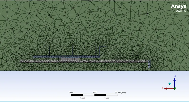
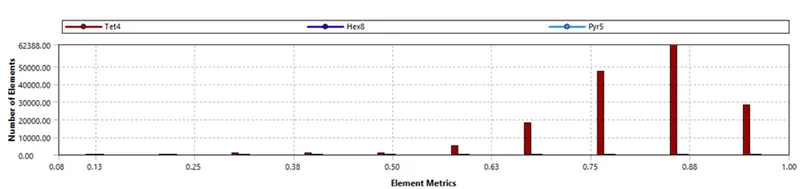
Mesh quality criteria:
Solution setup
Physics setup:
- It is a pressure-based solver type of steady state time to solve the problem and get results.
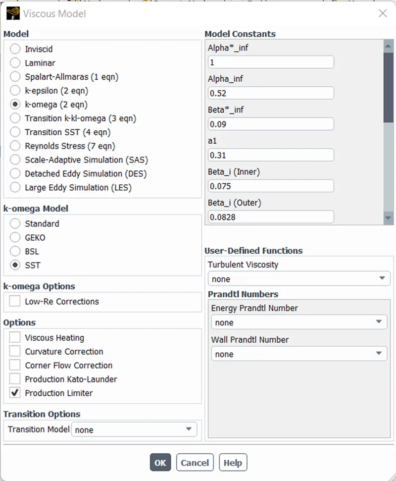
- As it has a high Reynolds number so will go to a k-omega SST model which is a turbulent model and contains temperature to predict conjugating heat transfer in this simulation.
| Solver type | Pressure based |
| Time state | steady state |
| Models | Energy on |
| Models |
k-omega realizable turbulence model
|
| Solution solver |
Hybrid intialization
|
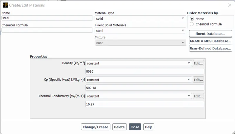
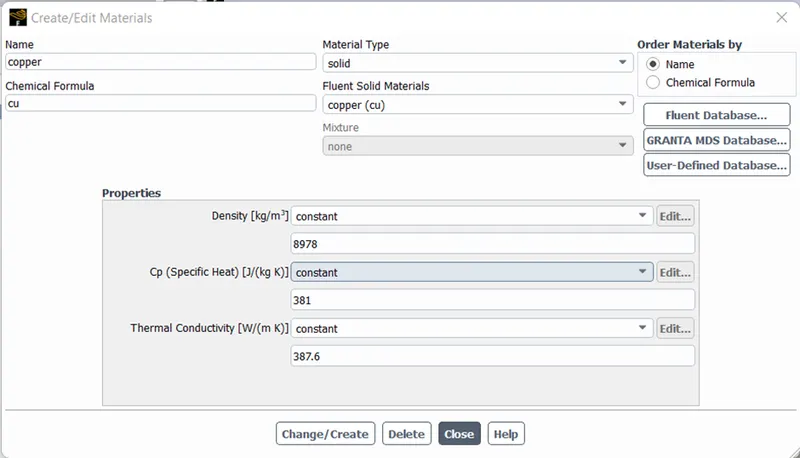
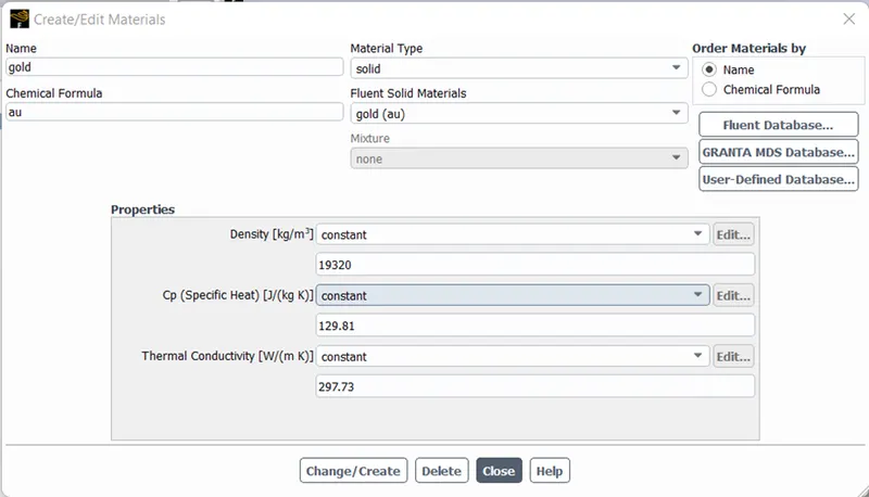
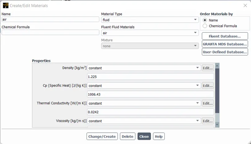
Create materials for each component:
| Parts | Material |
| Base | Steel |
| Fin | Copper (cu) |
| Processor | Gold (au) |
| Enclosure | Air |
Solid- Steel:
Solid- Copper:
Solid- Gold:
Fluid- Air:
Cell-zone conditions:
Base- Steel:
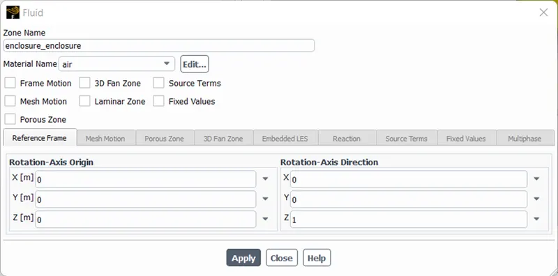
Enclosure- air:
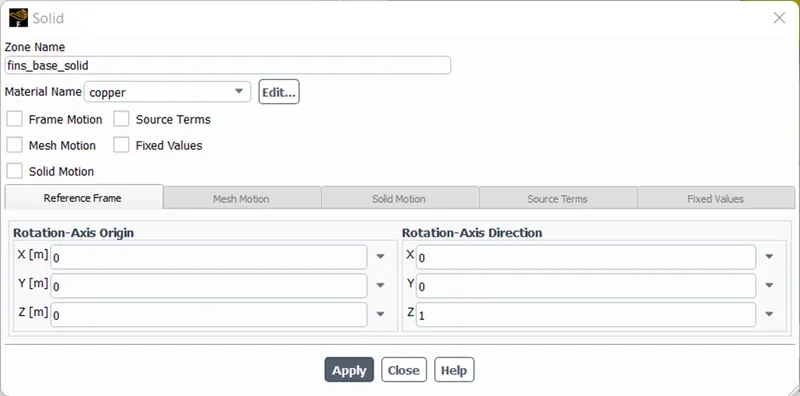
Fins- Copper:
Processor- Gold
- In this instance, we take into account the fact that our CPU is a source of heat generation.
- Go to Zones - Cell zones - and select the editing processor that is in the Solid to set up the source term.
- Following that, choose the material to be gold, allow the source terms, and set the energy source to 1.
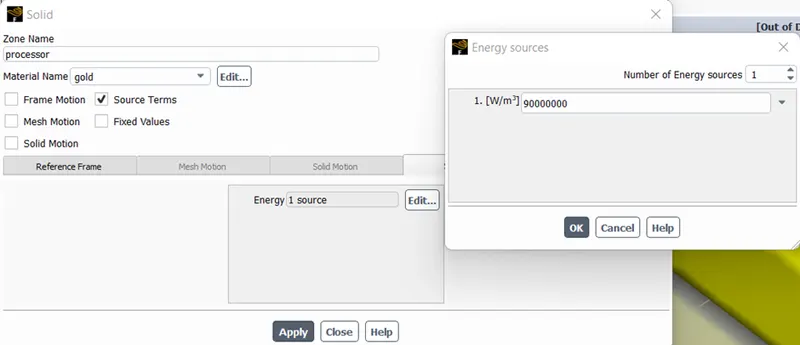
- The energy used by a processor is typically transformed into thermal energy. To determine the amount of heat produced by a processor, divide its entire volume by its power consumption.
- "The power usage of graphics cards today has significantly grown. The highest models require the power supply to deliver between 110 and 270 watts; in fact, a powerful graphics card operating at full capacity consumes as much power as the rest of the PC system's components put together."
- 5.76 Watts of heat energy are produced here. The CPU has a volume of (0.008*0.008*0.001) m^3. Therefore, a constant value of (5.76/(0.008*0.008*0.001)) w/m^3 = 9e7 is given to the Source.
Boundary conditions:
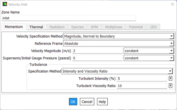
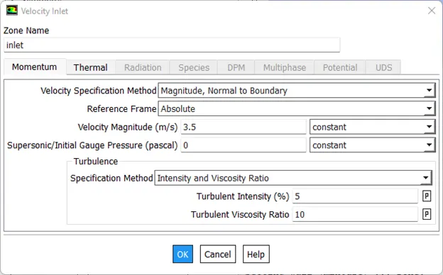
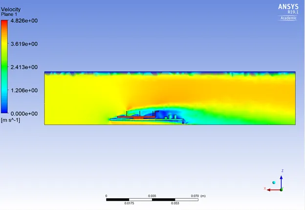
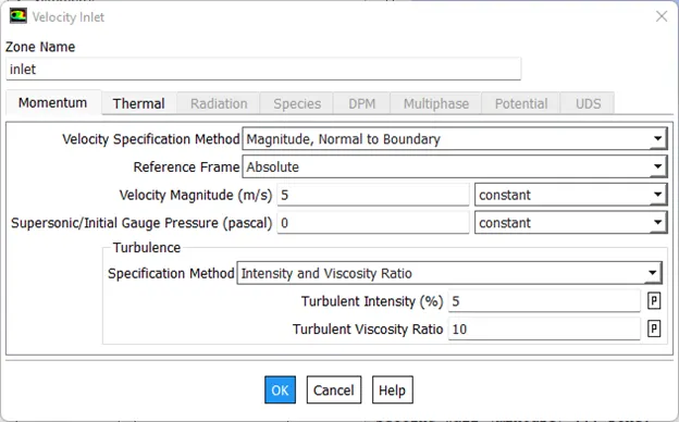
- Inlet: Inlet velocity at 2 m/s.
- Temperature as 300 K.
- Outlet: Pressure outlet at a gauge pressure of 0 Pa.
- Reference and initialization as standard.
- You can explicitly define all the variables using standard initialization. Fluent is designed to make it simple to provide the initial x, y, and z velocities as well as the domain-wide constant fields for temperature, pressure, and other variables. You can explicitly define all the variables using standard initialization. Fluent is designed to make it simple to provide the initial x, y, and z velocities as well as the domain-wide constant fields for temperature, pressure, and other variables. You can explicitly define all the variables using standard initialization. Fluent is designed to make it simple to provide the initial x, y, and z velocities as well as the domain-wide constant fields for temperature, pressure, and other variables.
Simulation output:
Residual plot
Temperature
Heat transfer coefficient
Post processor
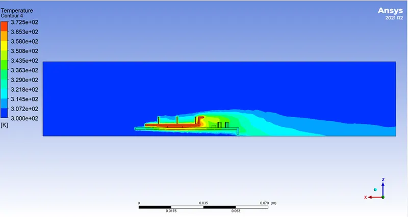
Temperature contour:
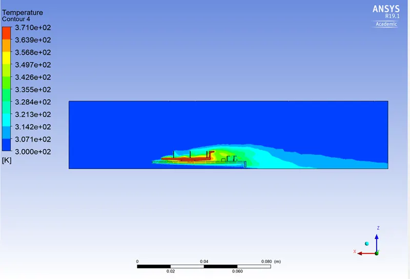
Global hotspot region:
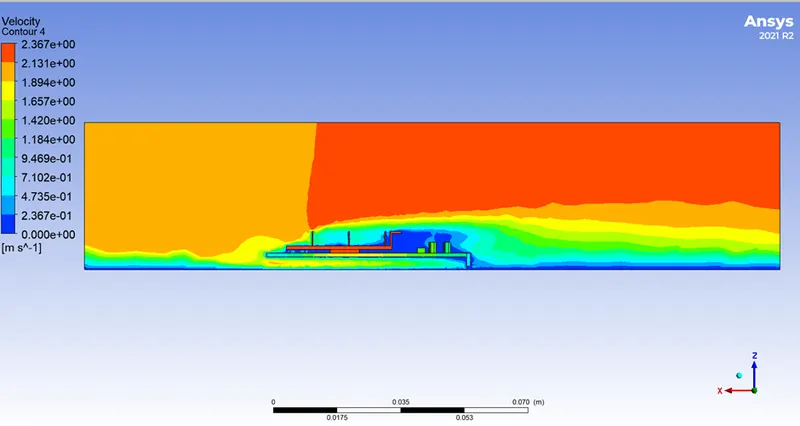
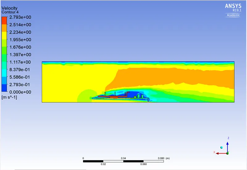
Velocity contour:
Refined mesh:
- To run the simulation by varying the velocity from 1m/sec to 5m/sec for at least 3 velocities and discuss the results.
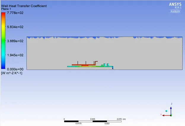
- To find out the maximum temperature and heat transfer coefficient attained by the processor.
| Re-fined mesh | |
| Base | 0.5 mm |
| Fin | 0.5 mm |
| Processor | 0.5 mm |
| Enclosure | 4 mm |
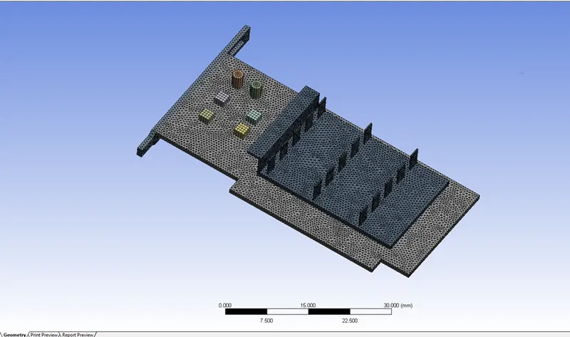
- The elements and nodes are,
| Nodes | Elements |
|
129263
|
750049
|
- The element quality criteria is,

Case 1: Velocity at 2 m/s
Residual plots:
Temperature:
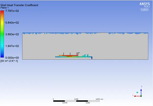
Wall heat transfer coefficient:
Global hotspot region:
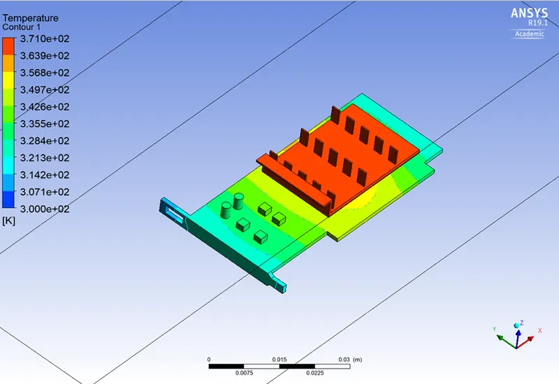
Temperature contour:
Velocity contour:
Case 2: Velocity at 3.5 m/s
Residual plots:
Temperature:
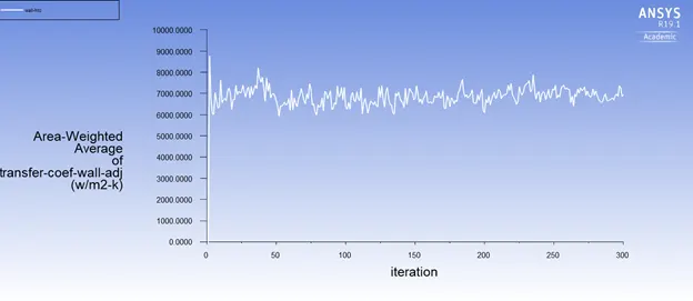
Wall heat transfer coefficient:
Global hotspot region:
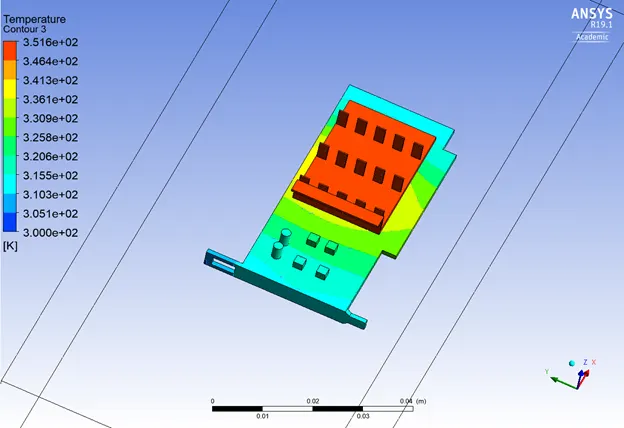
Temperature contour:
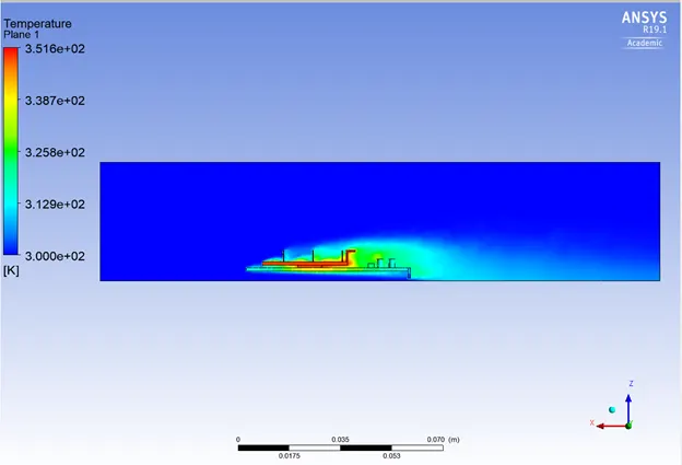
Velocity contour:
Wall heat transfer coefficient:
Case 3: Velocity at 5 m/s
Residual plots:
Temperature:
Wall heat transfer coefficient:
Global hotspot region:

Temperature contour:
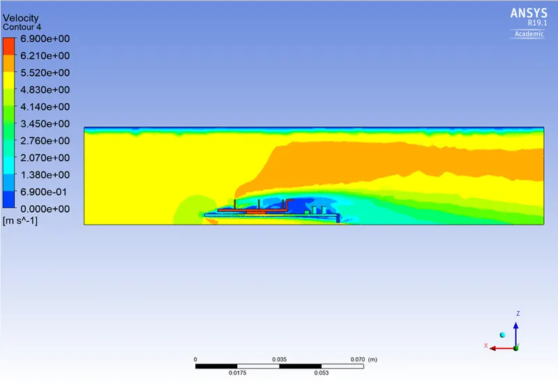
Velocity contour:
Wall heat transfer coefficient:
Results:
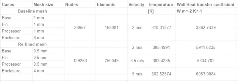
Grid independence test
This is the Grid dependency test, where, analysis begins with a coarse mesh and is refined to a finer mesh for each run until the results do not change significantly and depend on the grid size anymore. As the grid or mesh size approaches zero, the approximate solution is almost equal to the actual solution.
Conclusion:
- As the number of elements rises, precise temperature distribution data are achieved.
- It is apparent from the preceding data that as inlet velocity increases, the net temperature of graphics card components falls.
- As a result, it can be concluded that a higher inlet velocity leads to better cooling and a lower average temperature, protecting the components from harm.
- Furthermore, it is evident that components' temperatures rise as inflow velocity drops from 5 m/s to 1 m/s, further demonstrating that higher velocity improves cooling.