Week 6 - CHT Analysis on a Graphics card
CHT Analysis on a Graphics card
Aim: Perform a steady-state conjugate heat transfer analysis on a model of a graphics card and run the simulation for coarse and refined mesh.
Objectives:
- Run the simulation by varying the velocity from 1m/sec to 5m/sec for at least 3 velocities and discuss the results.
- Find out the maximum temperature and heat transfer coefficient attained by the processor.
- Prove that the simulation has achieved convergence with appropriate images and plots.
- Identify potential hotspots on the model.
Theory:
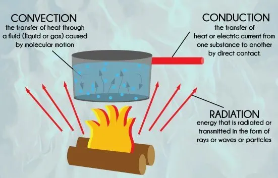
Conjugate heat transfer corresponds with the combination of heat transfer in solids and heat transfer in fluids. In solids, conduction often dominates whereas, in fluids, convection usually dominates. Conjugate heat transfer is observed in many situations. For example, heat sinks are optimized to combine heat transfer by conduction in the heat sink with the convection in the surrounding fluid.
Modes of Heat transfer are illustrated below images.
Examples of CHT:
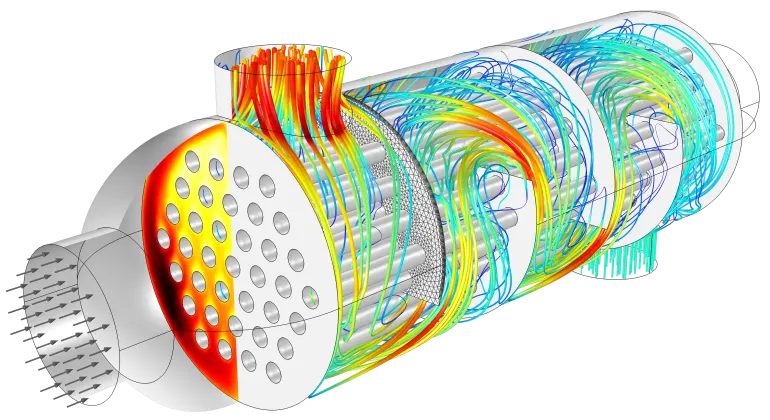
1. Heat Exchanger:
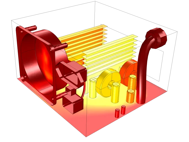
2. Power supply unit:
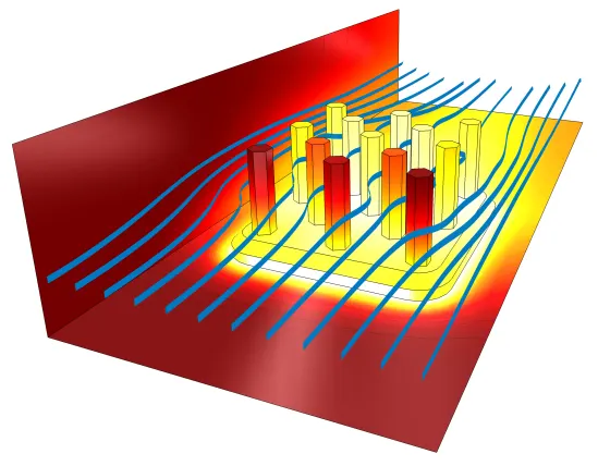
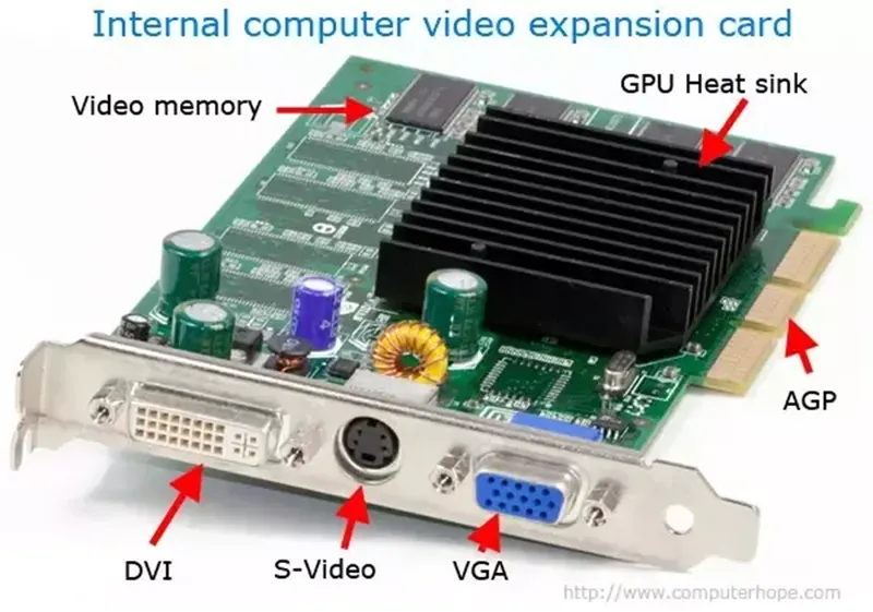
3. Graphics card, GPU:
Simulation and Results:
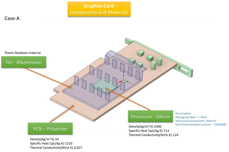
Assuming the Processor emits 1 watt of heat. Hence Heat Flux would be
q = Q/Vc = 1/64 X 10^9 = 15625000 W/M^3
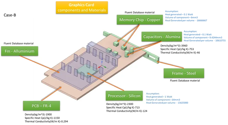
Geometry with assigned Materials:
Meshing
Setup
Setting up animation:
Solution run for the below cases:
Case-A
Case 1: Coarse Mesh (1 m/sec, Mesh Size 10mm and Body size 1mm & 2mm)
Case 2: Refined Mesh (Mesh Size 5mm & Body size 0.5mm)
Case 2.1: Velocity 1 m/sec
Case 2.2: Velocity 3 m/sec
Case 2.3: Velocity 5 m/sec
Case-B
Case 3: Refined Mesh (1 m/sec, Mesh Size 10 and Body size 1 & 2) with heat generated of 0.1 watts for chip and capacitors.
The table below shows the results of all the above cases.
CASE-1
Hot spots on the processor and on the fins
CASE-2 - Hot spots at the Processor and on the fins
Case-3
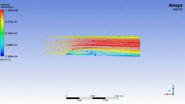
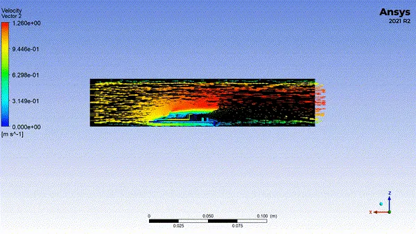
Velocity Animations
Conclusion:
1. The processor attends the maximum temperature hot spot and heat is dissipated to the atmosphere thru fins. Hence some regions of fins also attend high-temperature hot spots.
2. From the results table, we can conclude that if we increase in flow rate, the heat dissipation rate also increases.
3. in Case-3, Hot spots include memory chips and capacitors.
4. All results achieved convergency.
References: