Week 6 - CHT Analysis on a Graphics card
AIM: Perform a steady-state conjugate heat transfer analysis on a model of a graphics card.
OBJECTIVE:
- Simulate by varying the velocity from 1m/sec to 5m/sec for at least 3 velocities and discuss the results.
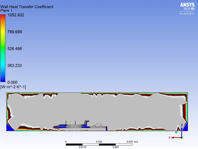
- Find out the maximum temperature and heat transfer coefficient attained by the processor.
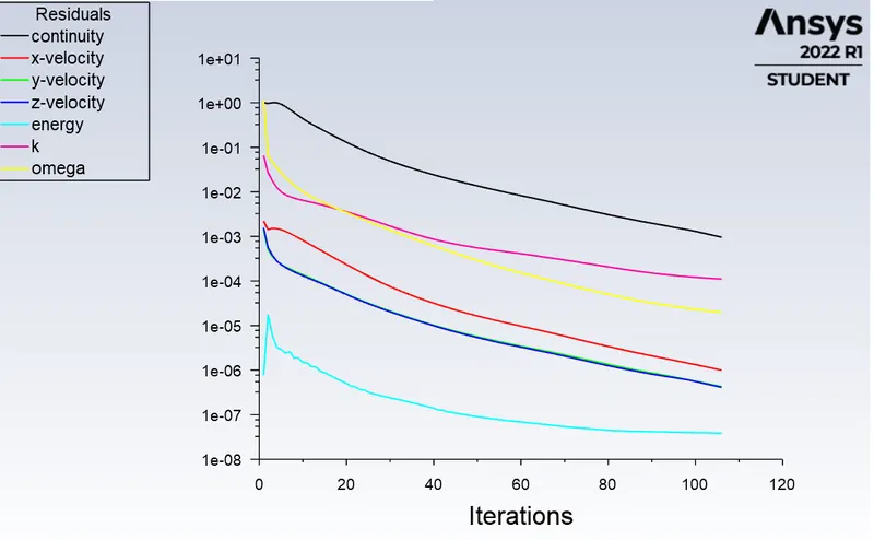
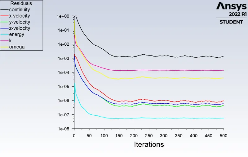
- Prove that the simulation has achieved convergence with appropriate images and plots.
- Identify potential hotspots on the model.
THEORY:
Conjugate Heat Transfer (CHT) Analysis:
Conjugate heat transfer is a type of heat transfer analysis between solids and fluid(s). This type of heat transfer includes both convection (between fluids) and conductive (between solids) heat transfer, as well as both forced and natural convection. Common applications and use cases of this thermal simulation type include electronics cooling, heat exchangers, industrial machinery, some AEC cases, and more.
Practical CHT problems are used to determine:
- The maximum and minimum temperature in various parts of the system. eg: combustion chamber, gas turbines, chemical vessels, etc.
- Temperature Distribution is related to the thermal stress over a particular wall or system etc.
- Overall heat transfer co-efficient.
Flow chart :
- Geometry preparation
- Mesh generation
- Fluent set up
- Post-processing
Geometry:
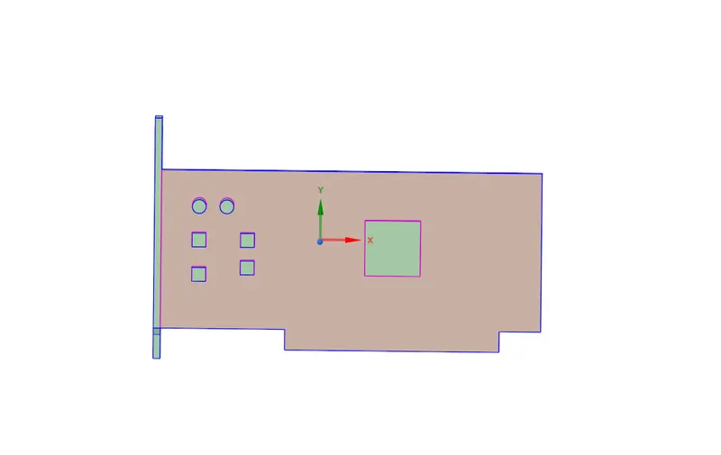
A step file is imported into ANSYS space claim:
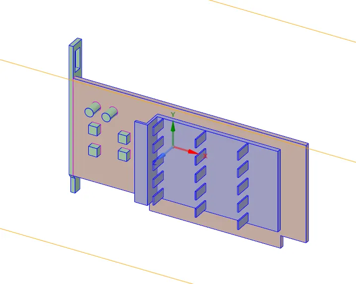
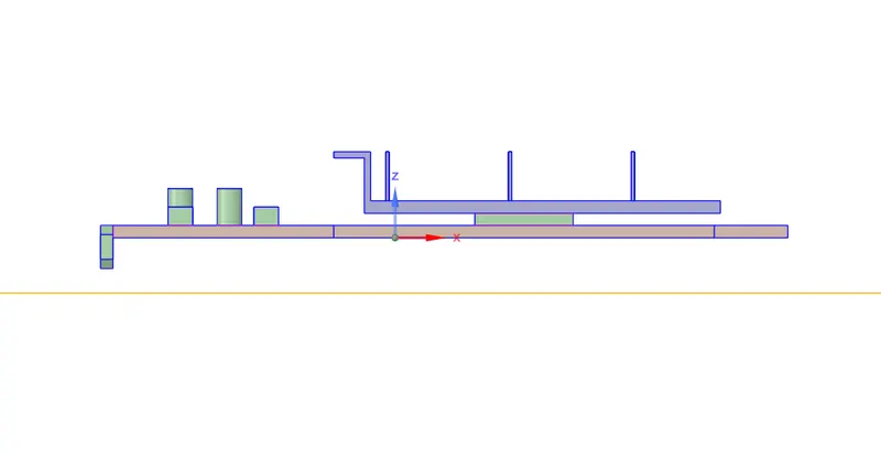
The processor:
Complete with enclosure:
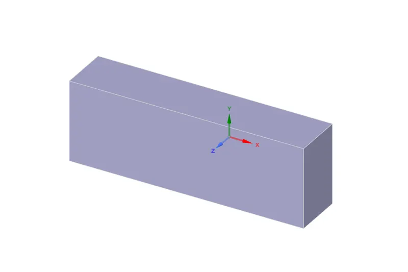
As there is a need of Conformal mesh, the share topology option is opted for. From the share option in Workbench. All the faces and edges that are common between the different components are shared
MESH:
We start the mesh by naming the parts
1. Inlet
2. outlet
3. Wall symmetry
4. Fins
5. Base
6. Processor
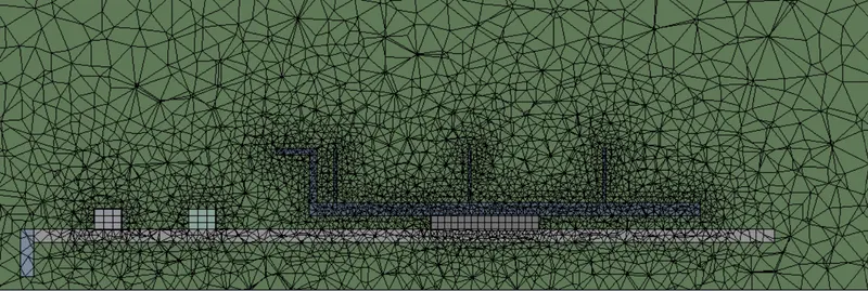
BASE LINE MESH AT DEFAULT SIZE
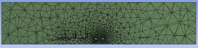
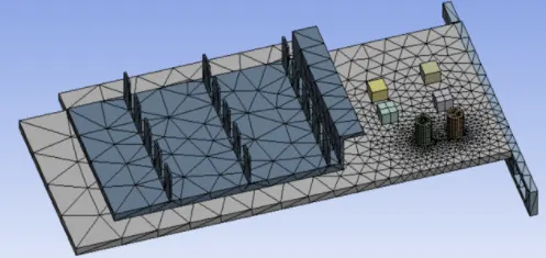
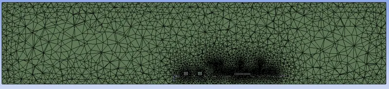
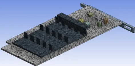
REFINED MESH at different location:
BASE: 3mm
PROCESSOR: 0.5mm
FINS: 0.5mm
OUTER ENCLOSER: 3mm
SET UP SOLUTION
Solver type: pressure based
Steady state solver
Energy equation is on
Turbulent model : K-Omega SST Model
BOUNDARY CONDITIONS:
Inlet velocity=5 m/s
initial temperature= 300k
CELL ZONE CONDITION:
Set processor core as source term as heat is generated by it in graphic card.
consider,
power supplies to core(p)= 6w
we have,
volume of processsor(v)=64 mm^3
there fore heat generated= p/v = 93750000 w/m^3
MATERIAL ASSIGNED ARE AS FOLLOWS:
BASE: steel
COMPONENTS: titanium
FINS: aliminium
PROCESSOR: gold
encloser is filled with air.
RESULTS:
BASE LINE MESH 5 m/s (inlet velocity)
RESIDUAL:
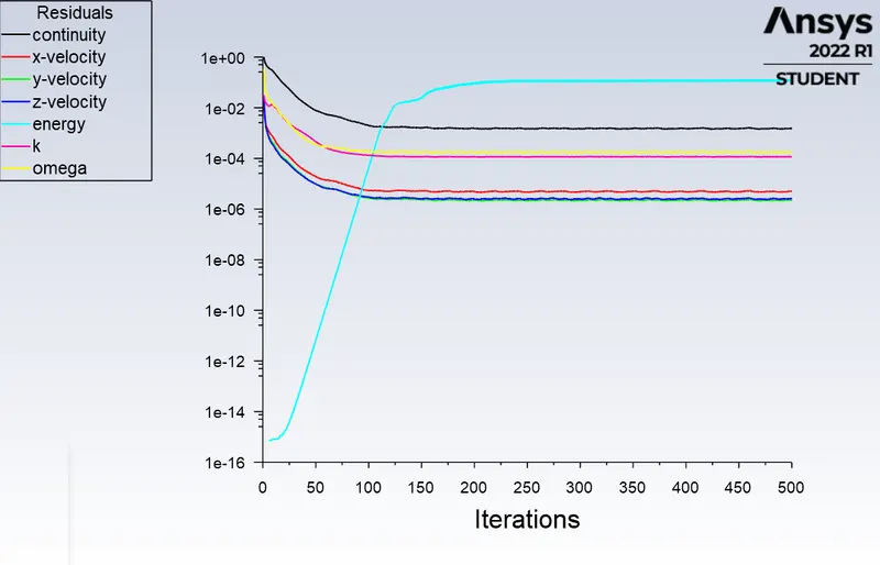
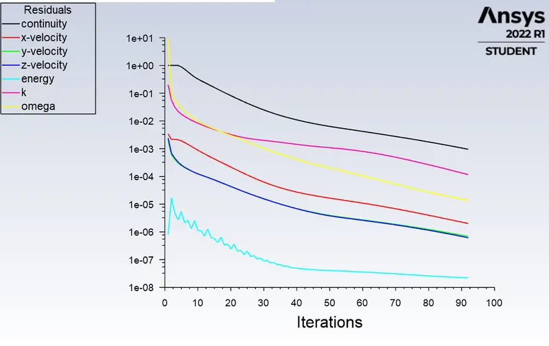
The residulas shows that the simulation is converged at 150 iteration
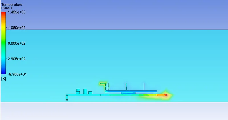
TEMPERATURE
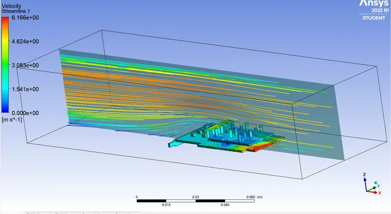
STRAM LINE
VECTOR LINE
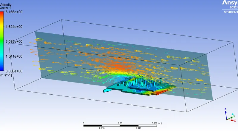
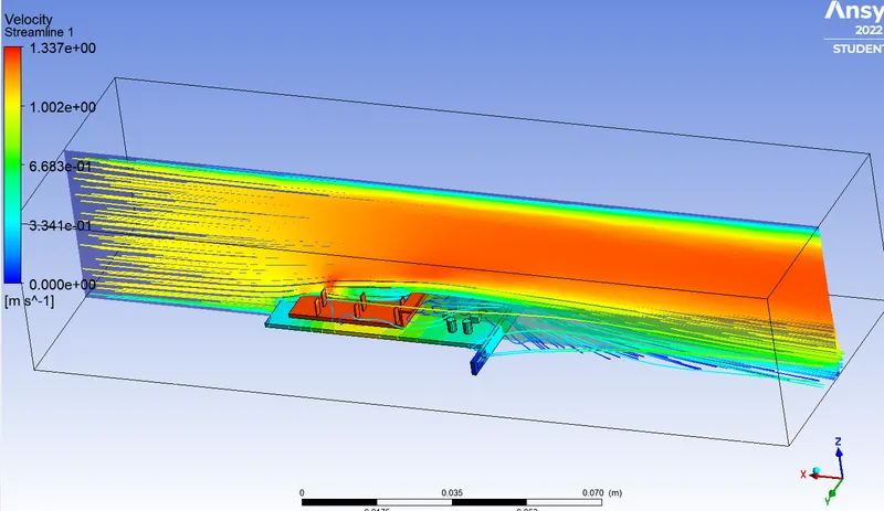
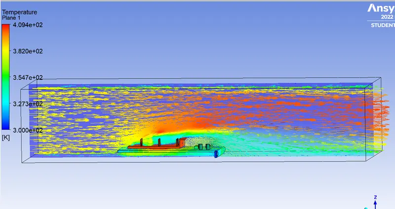
NOW REFINED MESH FOR 1 m/s (velocity)
RESIDUAL:
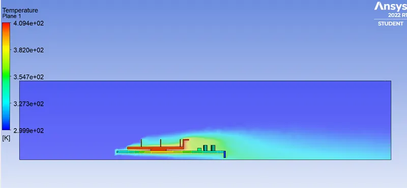
TEMPERATURE:
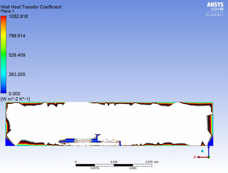
HEAT TRANSFER:
STREAM LINE:
VECTOR LINE:
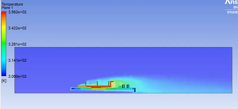
NOW REFINED MESH FOR 3m/s ( inlet velocity)
RESIDUAL:
TEMPERATURE:
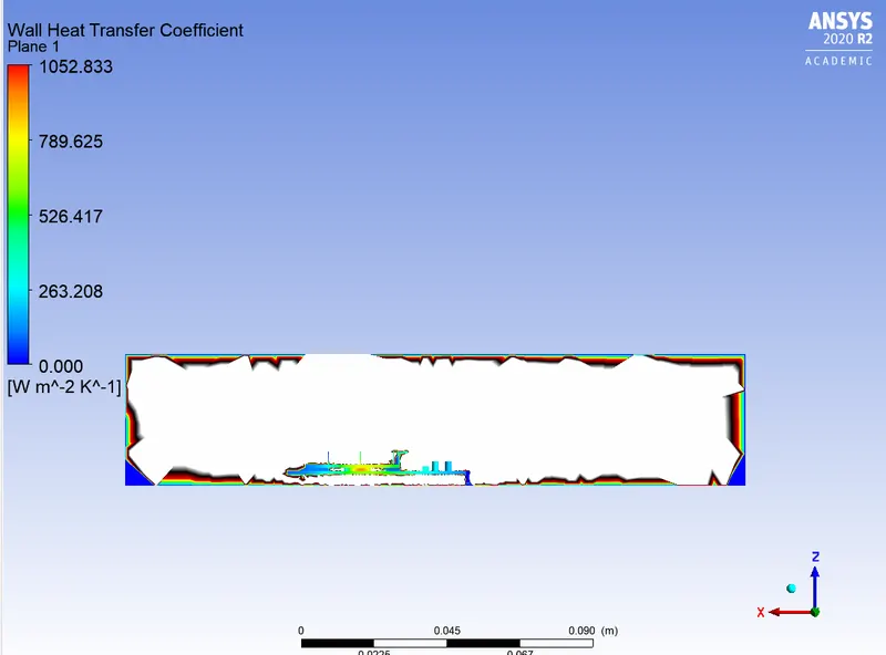
HEAT TRANSFER :
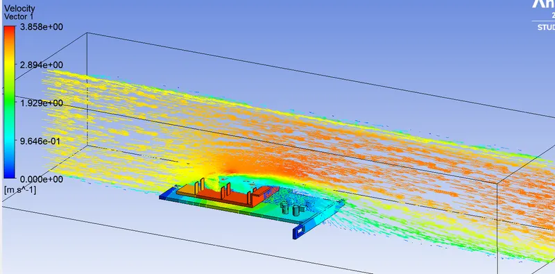
VECTOR LINE:
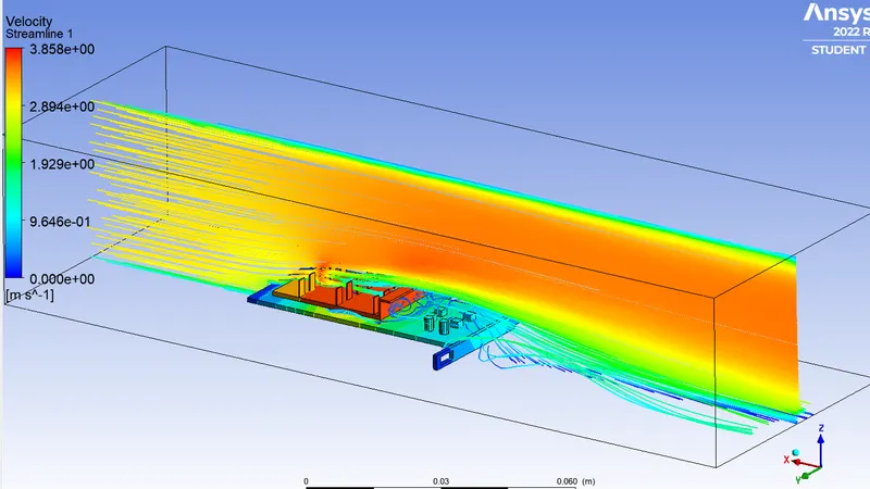
STREAM LINE:
NOW REFINED MESH FOR 5m/s ( inlet velocity)
RESIDUAL:
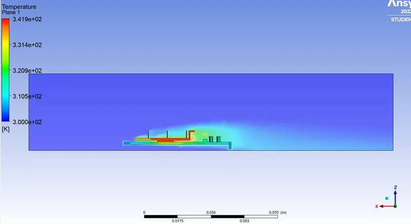
TEMPERATURE:
HEAT TRANSFER:
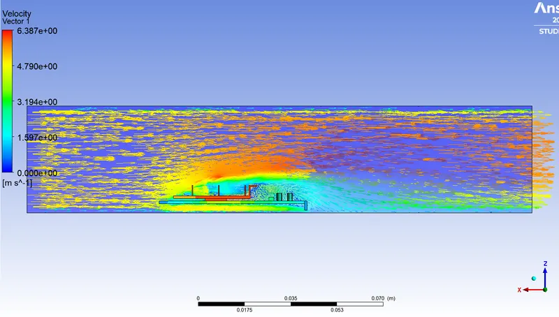
VECTOR LINE:
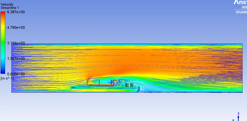
STREAM LINE:
CONCLUSION:
| CASES | VELOCITY(m/s) | TOTAL TEMPERATURE OF GRAPHICS CARD(K) | |
| Refined | 1 | 409 | |
| Refined | 3 | 358 | |
| Refined | 5 | 341 |
Higher velocity in a particular region means a higher Reynolds number. which means the maximum amount of heat transfer is taking place from fluid to the solid in that region. This also results in a Lower temperature of solid in that location.
The potential hotspot for the graphics card is the processor region. Maximum temperature is reached in that region
The Maximum temperature reached depends on the velocity of air at inlet. More the velocity, less is the maximum temperature reached.