Week 6 - CHT Analysis on a Graphics card
CHT ANALYSIS ON A GRAPHICS CARD
AIM:
- To perform a steady-state conjugate heat transfer analysis on a model of a graphics card.
- To run the simulation for best possible mesh with combination of coarse and refined mesh in different regions.
GIVEN:
- Graphics Card STEP file
- Inlet Velocity Range 1m/sec to 5m/sec
OBJECTIVES
- Run the simulation by varying the velocity from 1m/sec to 5m/sec for at least 3 velocities and discuss the results.
- Find out the maximum temperature and heat transfer coefficient attained by the processor.
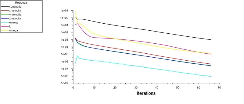
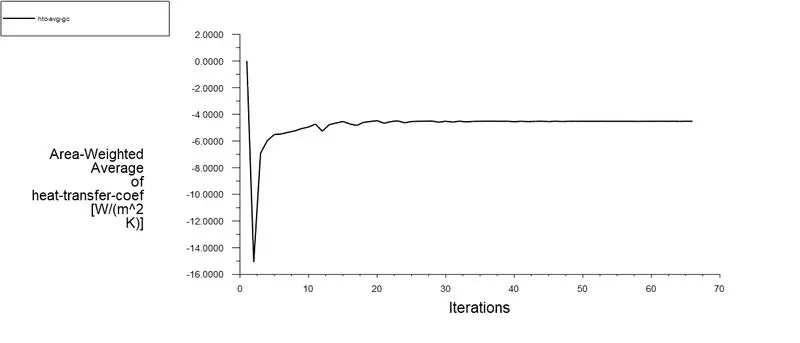
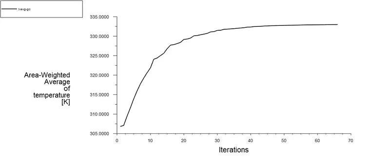
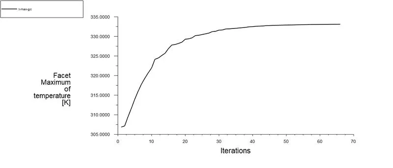
- Prove that the simulation has achieved convergence with appropriate images and plots.
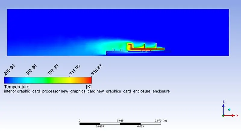
- Identify potential hotspots on the model.
ASSUMPTIONS
Heat capacity : 1W
Silicon Material Properties
Thermal Conductivity = 153 (W/m.k)
Specific Heat Capacity = 703 (J/kg. K)
Density = 2330 (Kg / m^3)
Polystyrene Material Properties
Thermal Conductivity = 0.027 (W/m.k)
Specific Heat Capacity = 1210 (J/kg. K)
Density = 55 (Kg / m^3)
STEPS USED FOR SIMULATIONS
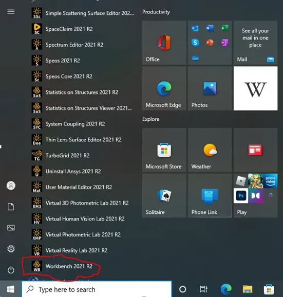
Click on red encircled "Workbench 2021 R2" as shown in the above image to start the simulation.
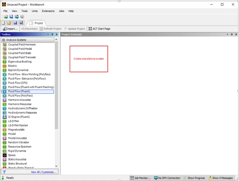
Click On Fluid Flow (Fluent) under Analysis Systems and drag it to create a standalone system.
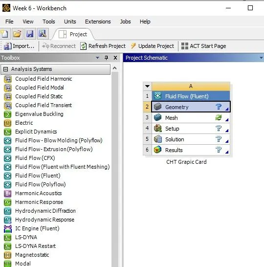
Rename the Project by using the left click and then click the Geometry.
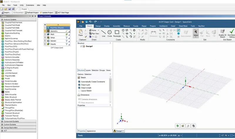
On clicking the geometry, the Space Claim window opens as shown in the above image.
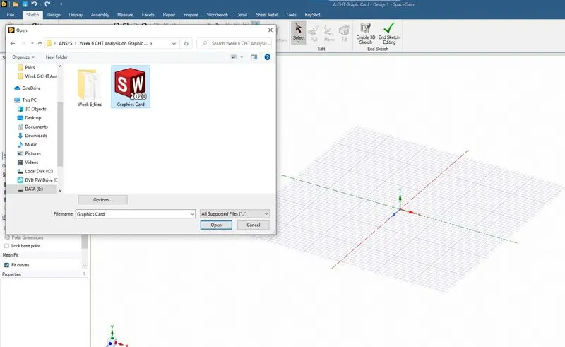
Open the dowloaded Graphics Card.STEP file as shown in the above image.
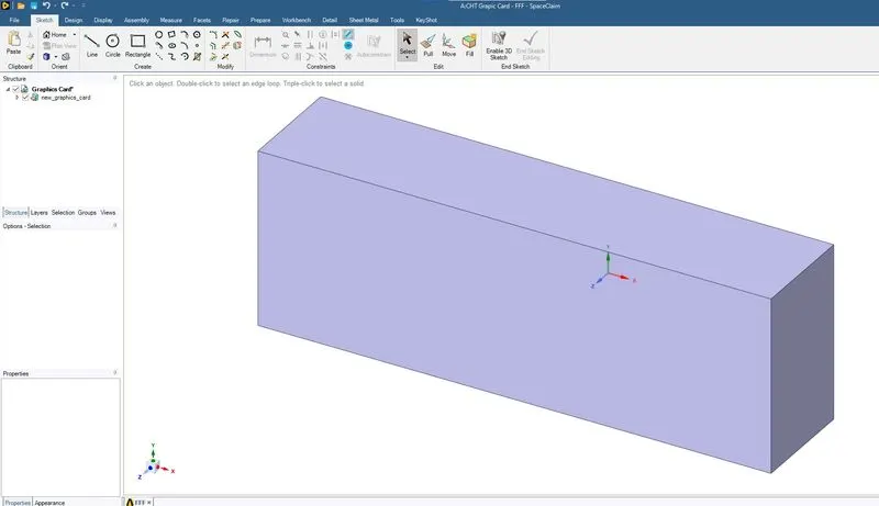
The above image represents the screen after opening the step file in Space Claim. The graphics card model is enclosed in an enclosure.
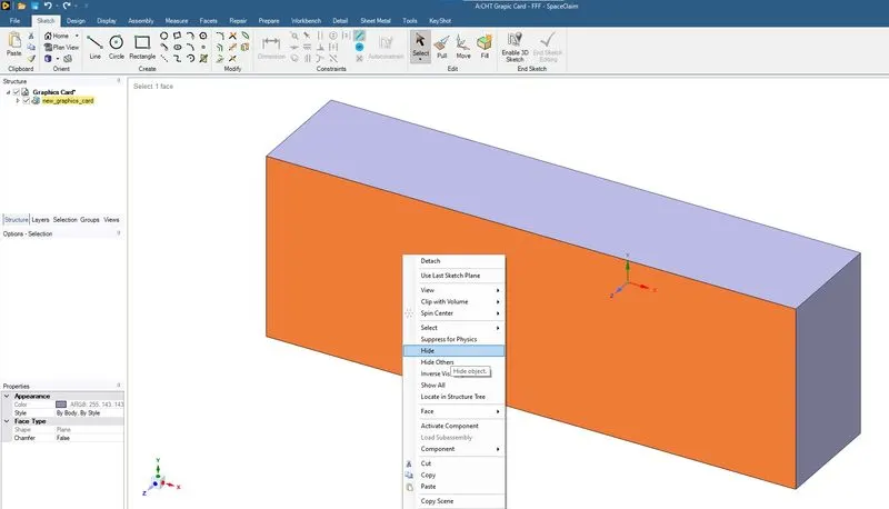
Using the Hide option the enclosure has been hidden as shown in the above images.
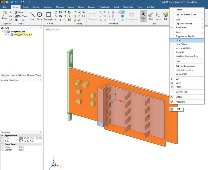
Using the Hide option the selected body has been hidden as shown in the above images.
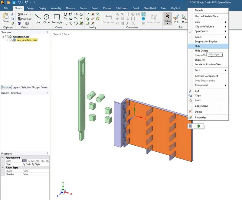
Using the Hide option the selected body has been hidden as shown in the above images.
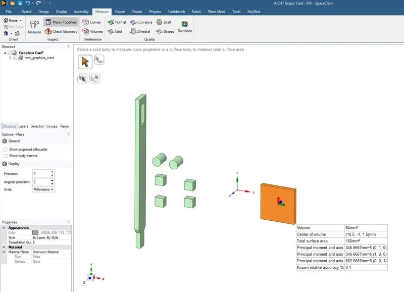
The selected body is graphic card processor. Using the mass properties under Measure tab we get the parameters as shown in the above image.
An interested parameter for us is the volume which will be taken into calculation for volumetric heat generation.
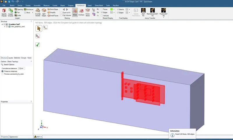
Share topology is used for creating the linked meshes at the common edges and common faces.
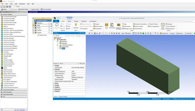
On clicking the mesh module, the meshing window opens as shown in the above images.
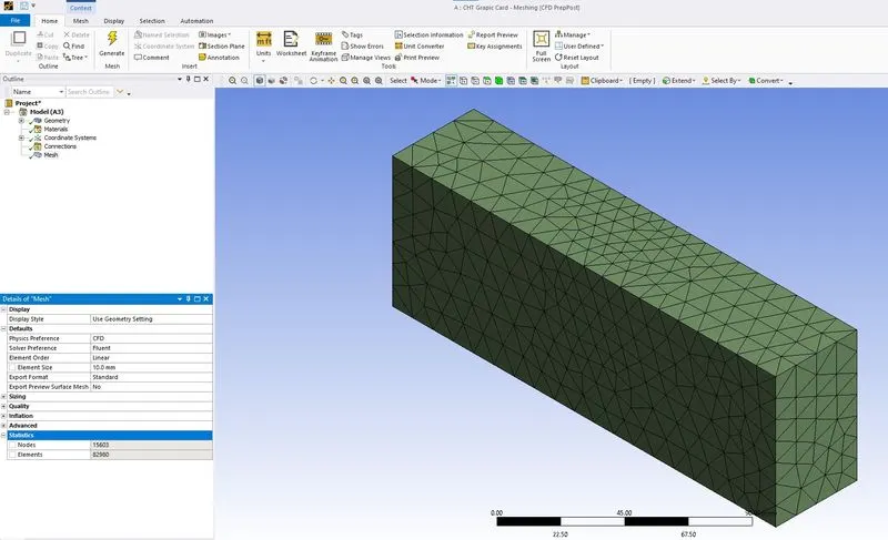
On clicking the Generate under Mesh tab, a deault mesh is generated as shown in the above image.
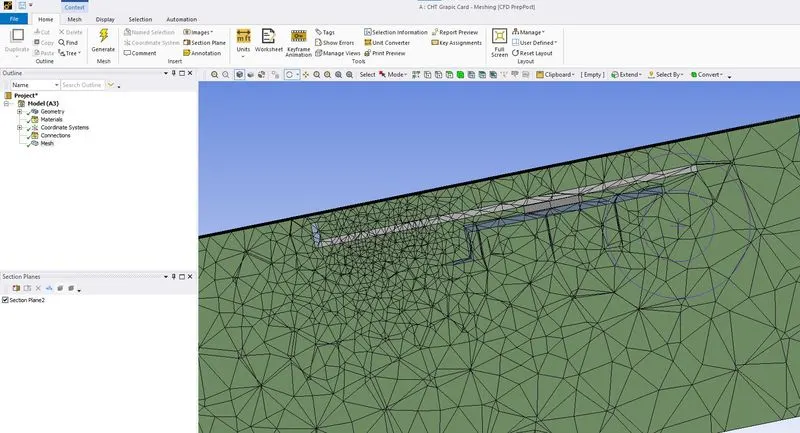
The sectional view of the meshing near the graphic card model.
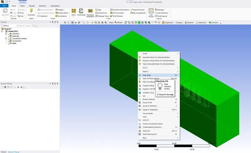
Using the body selection, the highlighted body is selected as shown in the above image. The F8 button or Hide body option is used to hide the selected body.
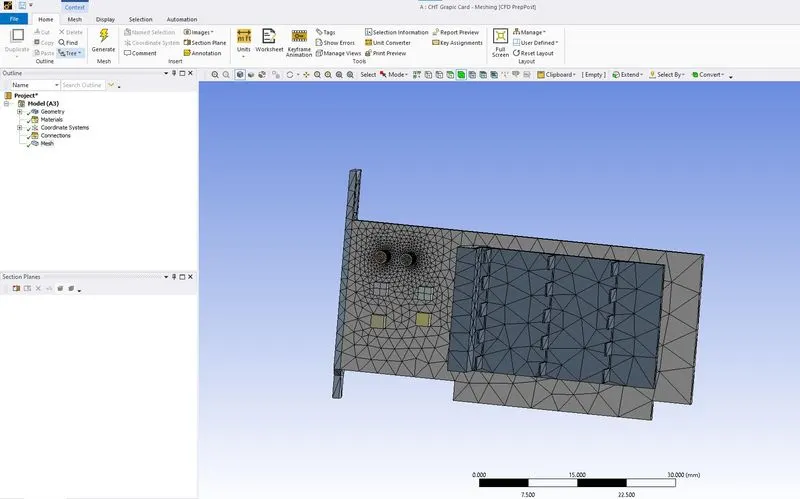
The meshing at the graphic card model is as shown in the above image. Capture curvature is enabled.
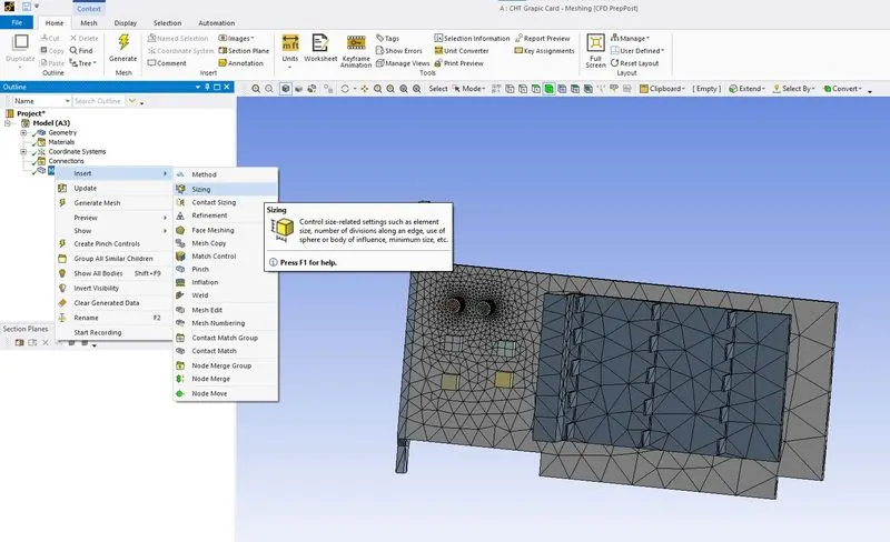
Using Insert Sizing Option, the mesh for the graphic card model is refined.
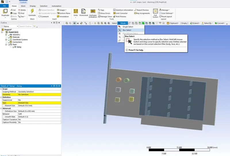
Using the Box Select option and body selection the complete graphic card model is selected as shown in the above image.
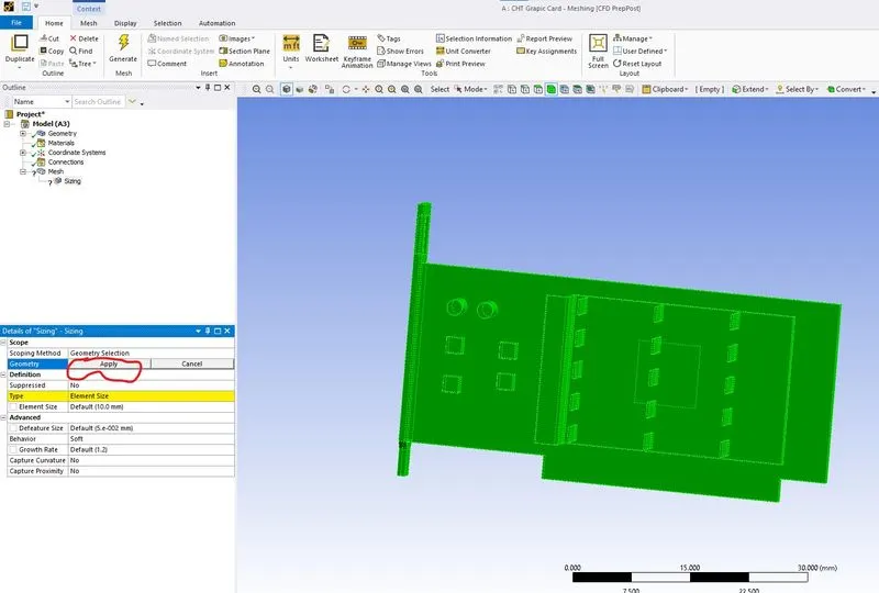
The geometry selection is applied for the selected body.
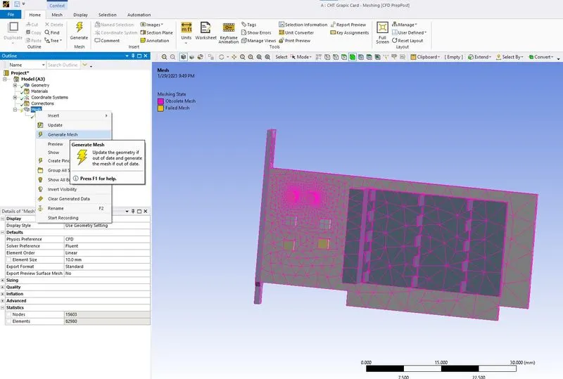
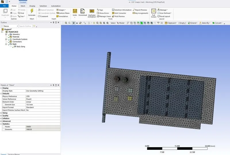
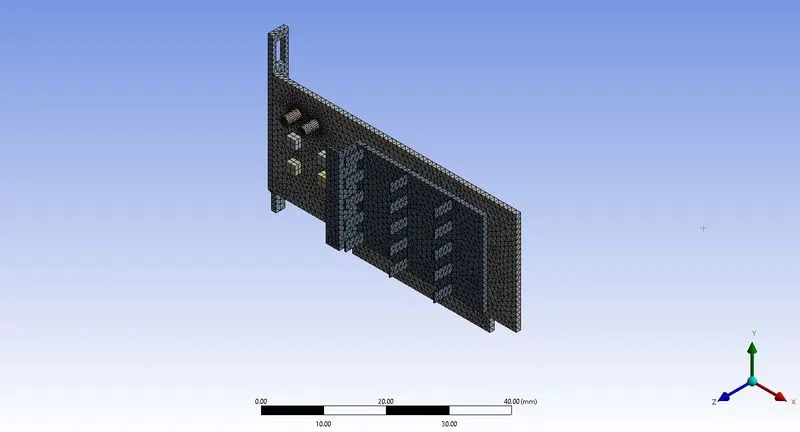
The updated mesh for the grahic card model after body sizing along with the number of elements to be set as coarse mesh.
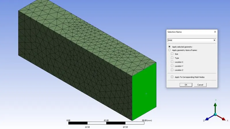
Using Named selection, the selected surface is named as Inlet.
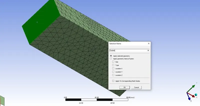
Using Named selection, the selected surface is named as Outlet.
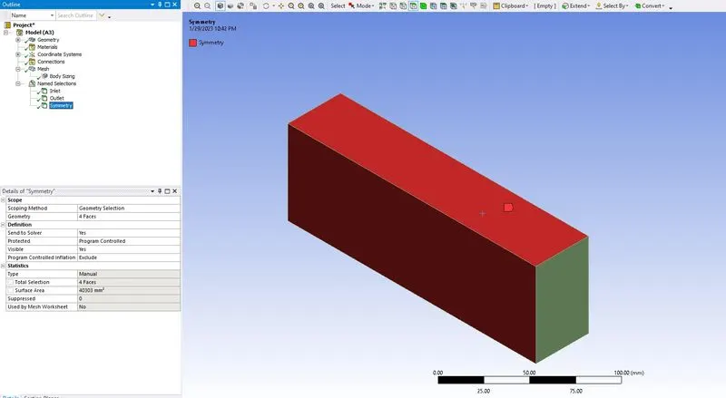
The selected faces are named as symmetry using named selection.
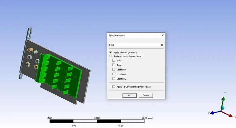
Using the named selection the selected body is named as Fin.
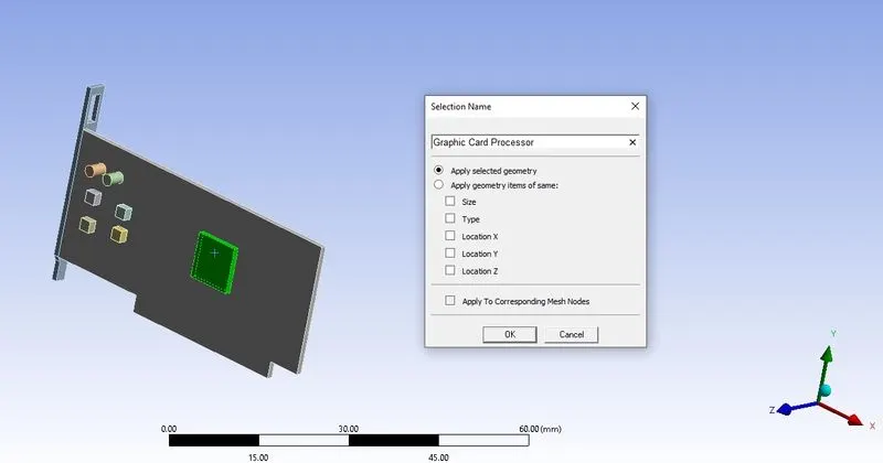
Using the named selection the selected body is named as Graphic Card Processor.
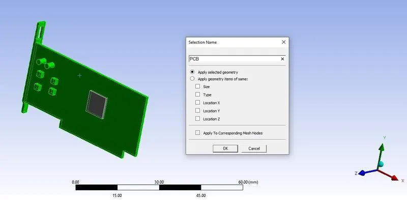
Using the named selection the selected body is named as PCB.
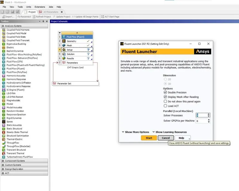
The Ansys Fluent Set up is started as shown in the above image.
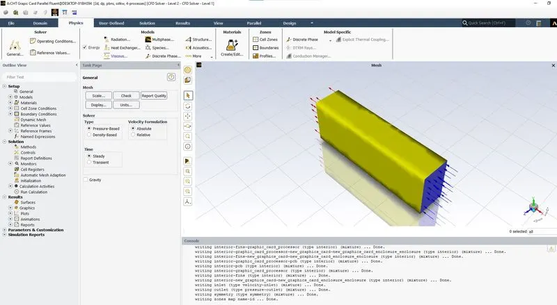
Under Physics Tab in Models the Energy is enabled as shown in the above image.
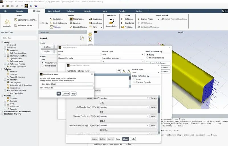
The assumed material Silicon for Graphic Card Processor is defined as shown in the above image.
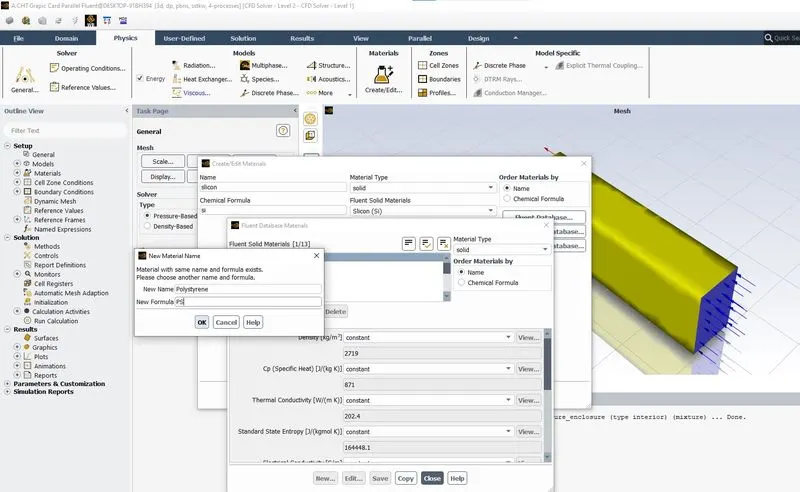
The assumed material Polystyrene for PCB is defined as shown in the above image.
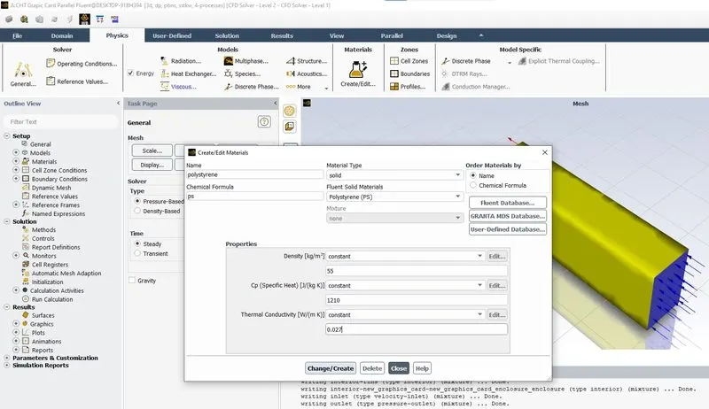
The Polystyrene Material after defining in the materials fluent data base.
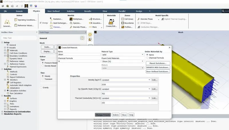
The Silicon material after defining in the materials fluent data base.
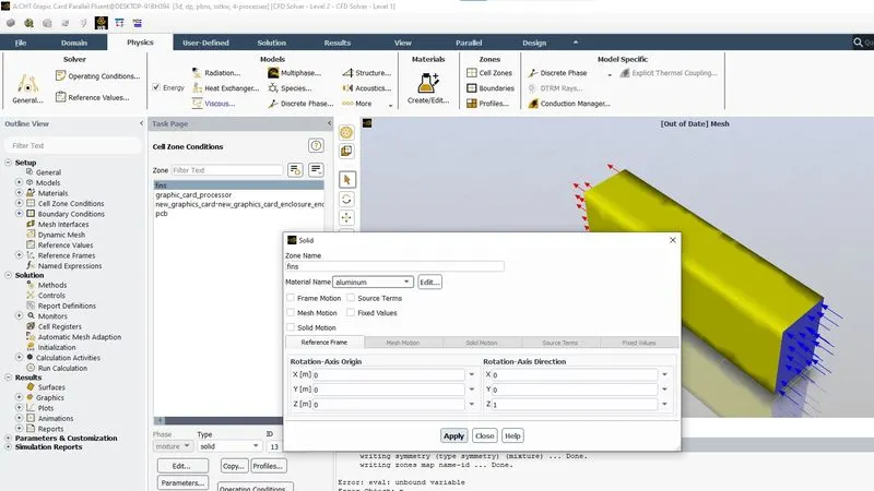
Assigning the material to Fins as aluminium in Cell Zone Conditions.
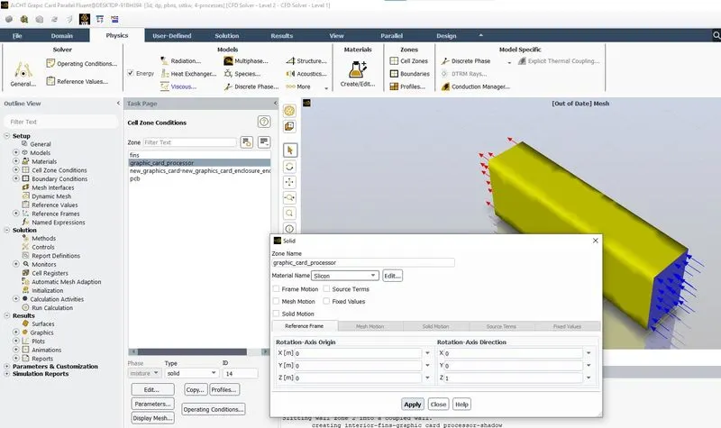
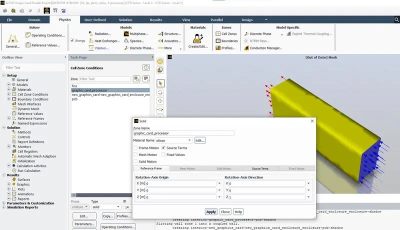
Assigning the material to graphic card processor as Silicon in Cell Zone Conditions.
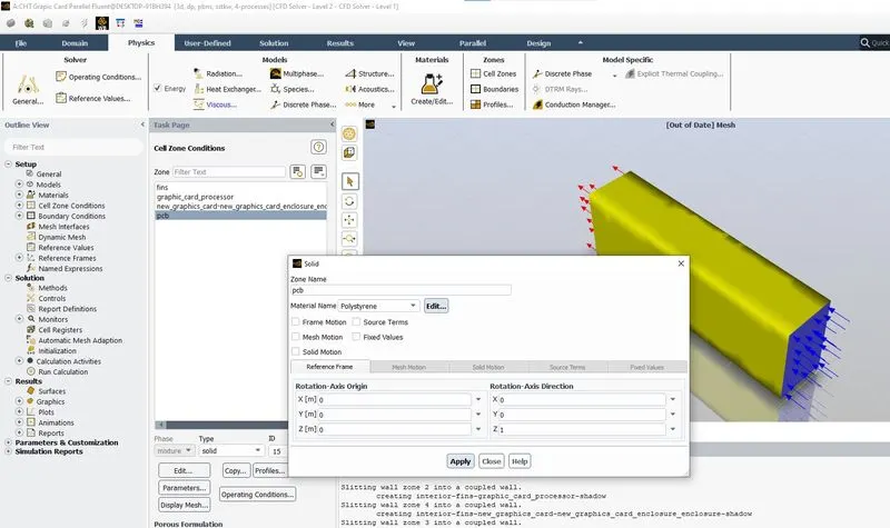
Assigning the material to PCB as Polystyrene in Cell Zone Conditions.
Enabling the source term in cell zone conditions and defining the volumetric heat generation.
Volumetric heat generation = Heat Capacity / Volume of Graphic Card Processor
= 1 (W) / (64 x 10^-9) (m^3)
= ((10^9) / 64) (W / (m^3))
= 15625000 (W/(m^3))
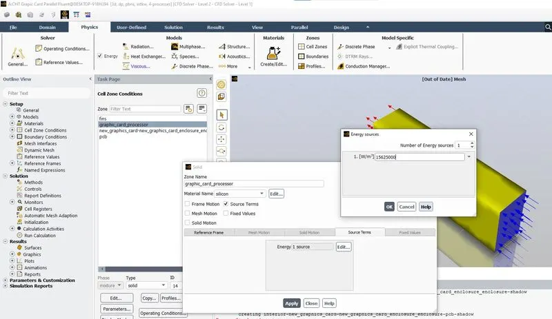
Volumetric Heat Generation is defined as shown in the above image.
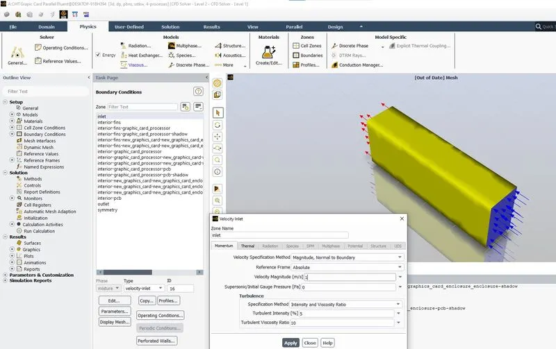
Inlet Velocity is defined as shown in the above image.
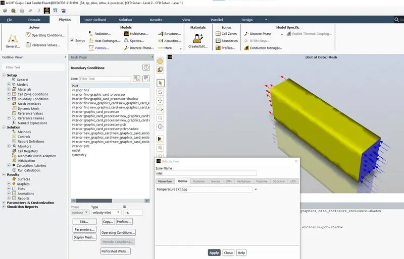
The Inlet Temeperature is defined as shown in the above image.
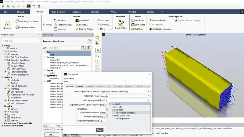
Inlet velocity is set as input parameter for parametric study.
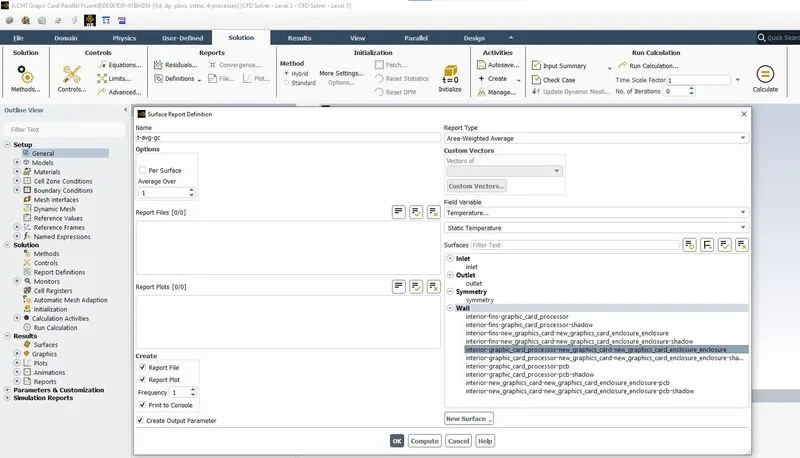
Average temperature plot is defined as shopwn in the above image.
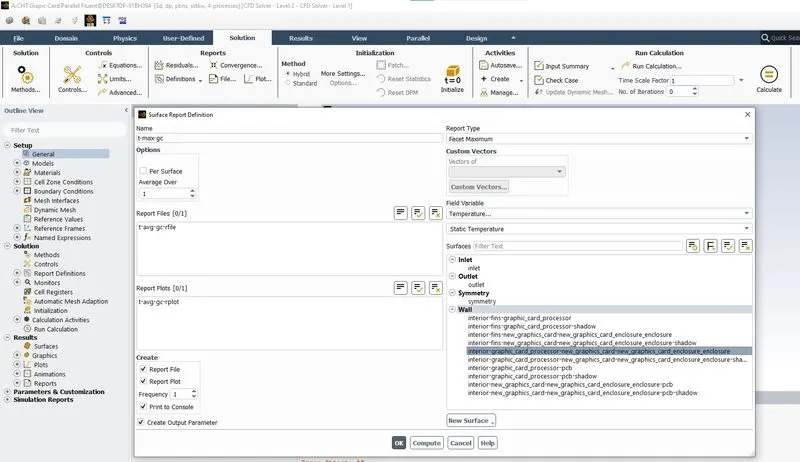
Maximum temperature plot is defined as shownm in the above image.
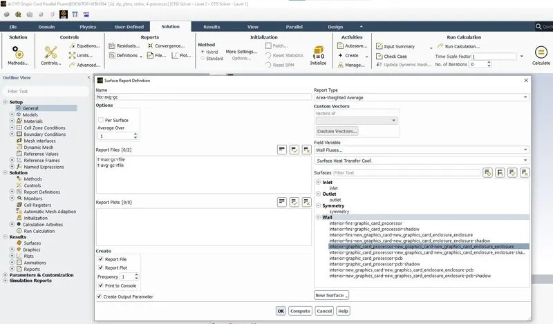
Surface heat transfer coefficient plot is defined as shown in the above image.
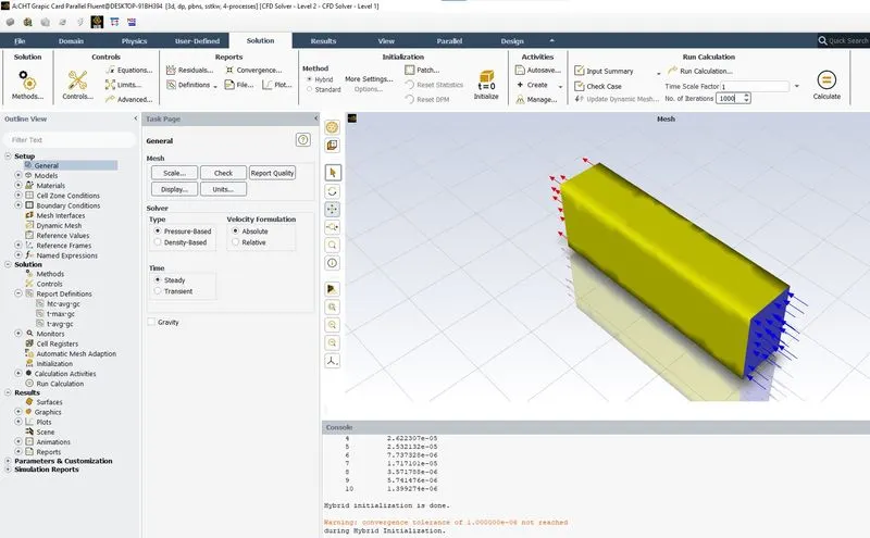
Hybrid initialization is defined as shown in the above image and the calculation is run for 1000 iterations.
Case done using ANSYS Fluent
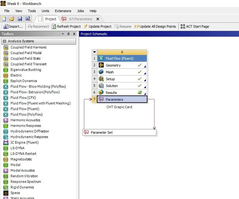
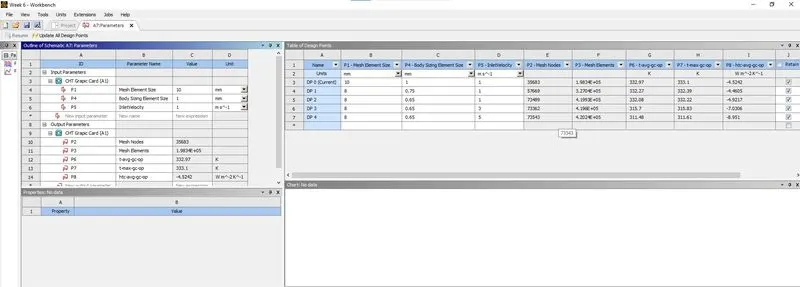
Parametric study has been performed by setting the input and output parameters
1 DP 0 COARSE MESH VEL 1m/s
1.1 SCALED RESIDUALS
1.2 AVERAGE HTC (Heat Transfer Coefficient)
1.3 AVERAGE TEMPERATURE
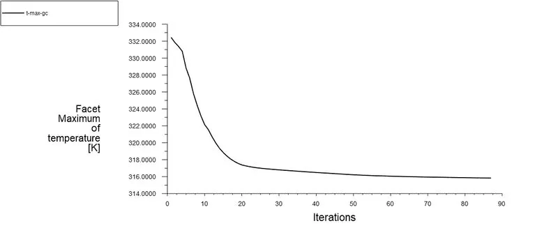
1.4 MAXIMUM TEMPERATURE
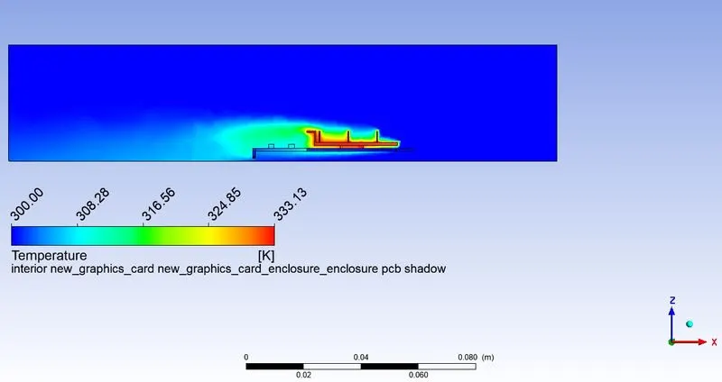
1.5 TEMPERATURE CONTOUR
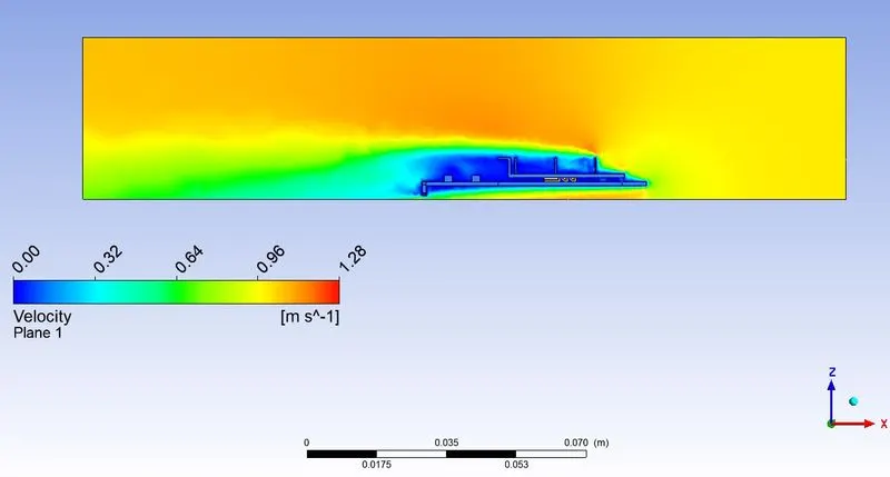
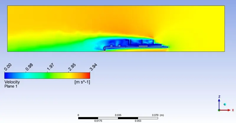
1.6 VELOCITY CONTOUR
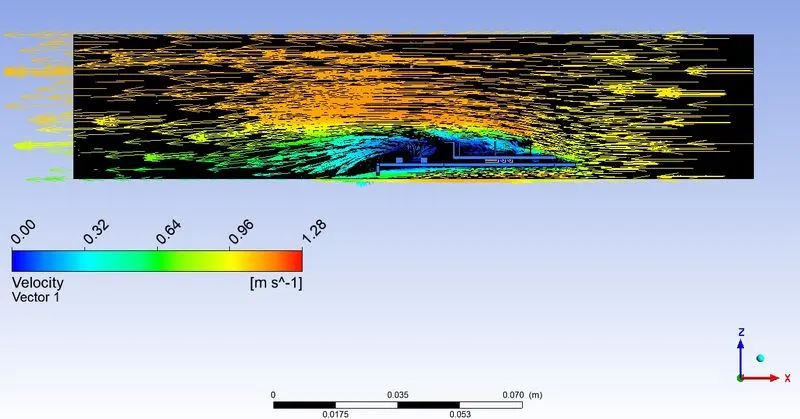
1.7 VELOCITY VECTOR PLOT
2 DP 1 FINE1 MESH VEL 1m/s
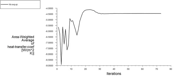
2.1 AVERAGE HTC (Heat Transfer Coefficient)
2.2 AVERAGE TEMPERATURE
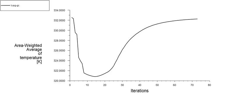
2.3 MAXIMUM TEMPERATURE
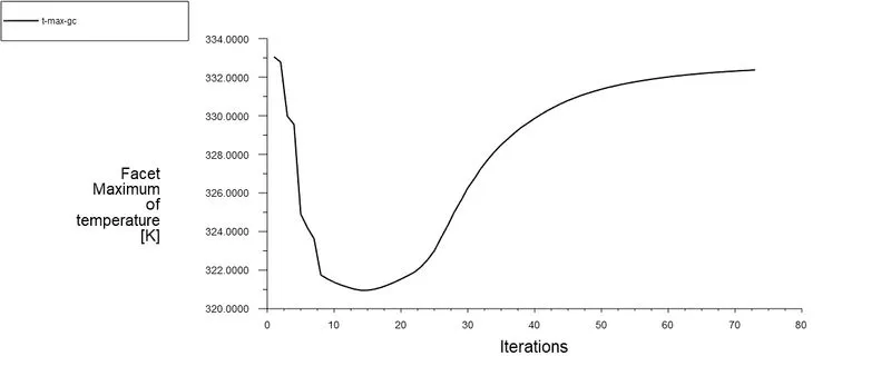
2.4 TEMPERATURE CONTOUR
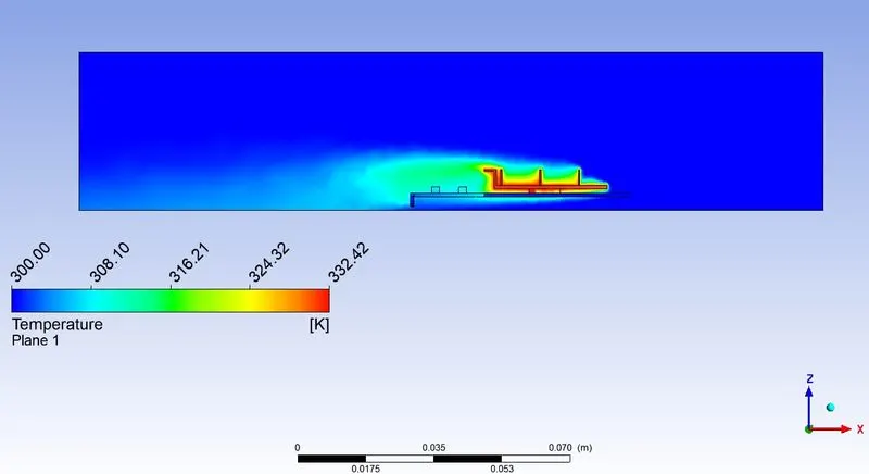
2.5 VELOCITY CONTOUR
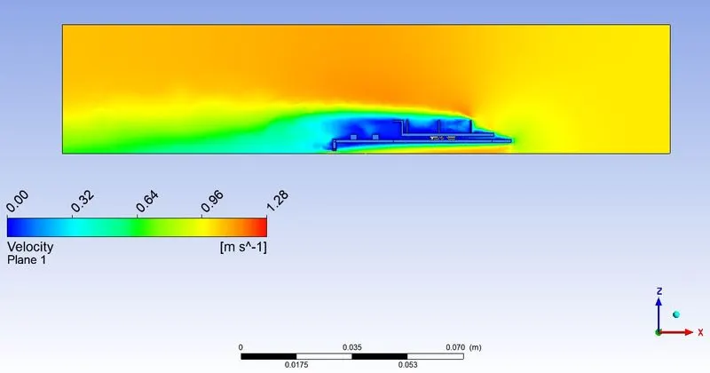
2.6 VELOCITY VECTOR PLOT
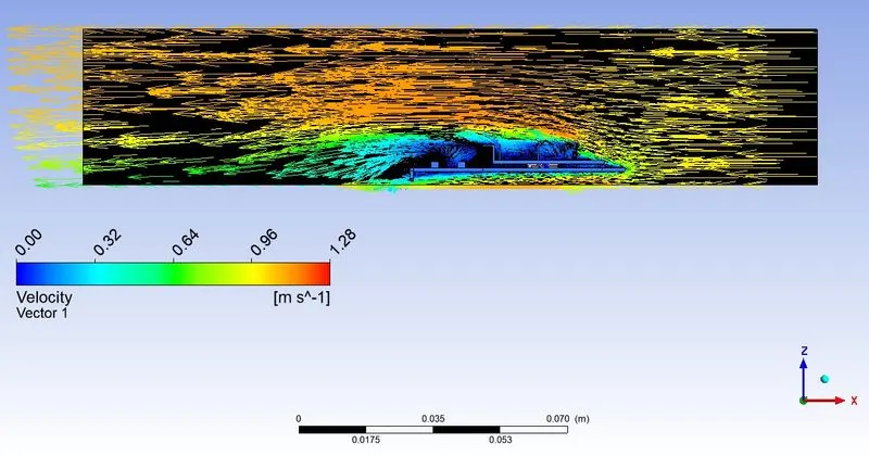
3 DP 2 FINE2 MESH VEL 1m/s
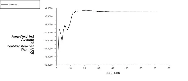
3.1 AVERAGE HTC (Heat Transfer Coefficient)
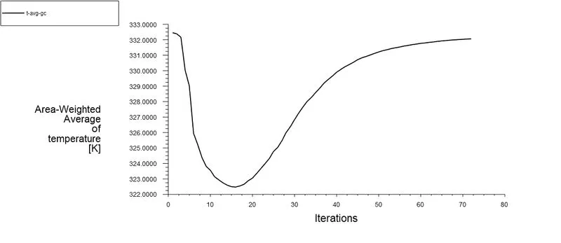
3.2 AVERAGE TEMPERATURE
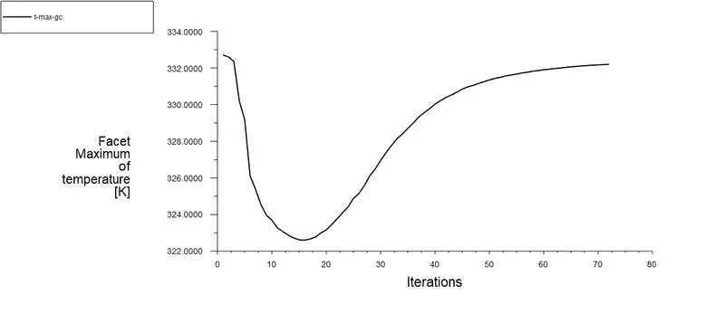
3.3 MAXIMUM TEMPERATURE
3.4 TEMPERATURE CONTOUR
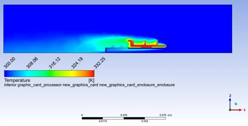
3.5 VELOCITY CONTOUR
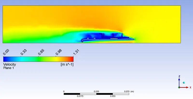
3.6 VELOCITY VECTOR PLOT
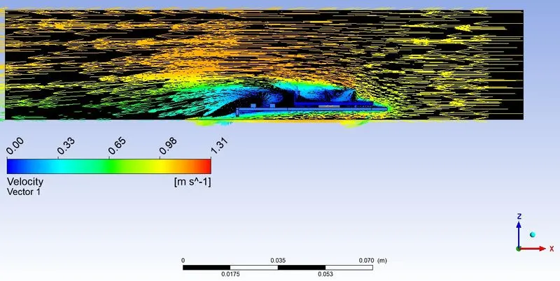
4 DP 3 FINE2 MESH VEL 3m/s
4.1 AVERAGE HTC (Heat Transfer Coefficient)
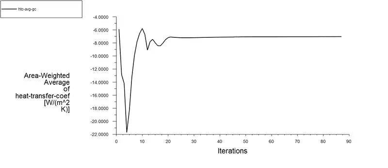
4.2 AVERAGE TEMPERATURE
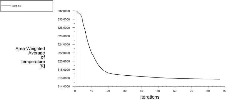
4.3 MAXIMUM TEMPERATURE
4.4 TEMPERATURE CONTOUR
4.5 VELOCITY CONTOUR
4.6 VELOCITY VECTOR PLOT
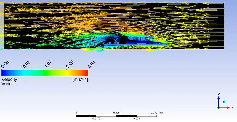
5 DP 3 FINE2 MESH VEL 5m/s
5.1 AVERAGE HTC (Heat Transfer Coefficient)
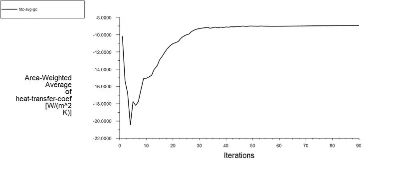
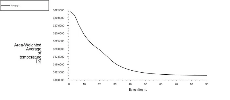
5.2 AVERAGE TEMPERATURE
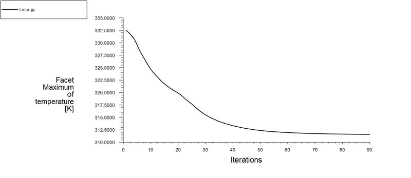
5.3 MAXIMUM TEMPERATURE
5.4 TEMPERATURE CONTOUR
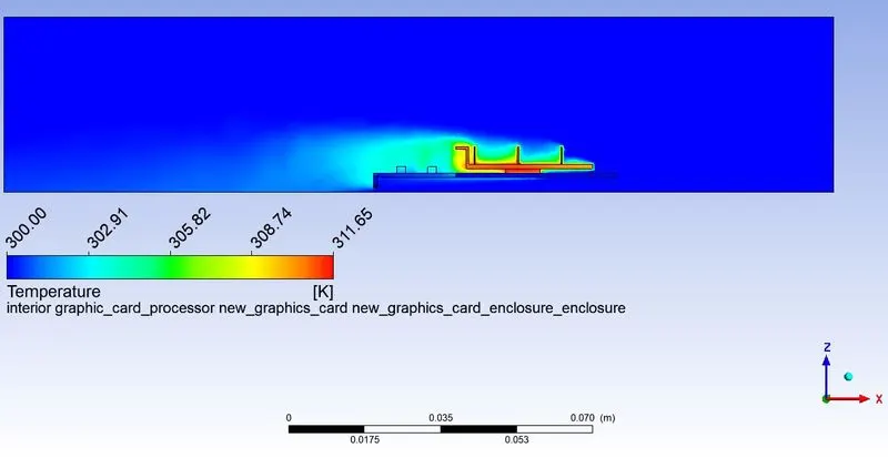
5.5 VELOCITY CONTOUR
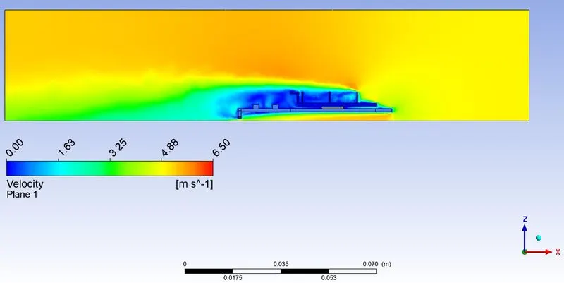
5.6 VELOCITY VECTOR PLOT
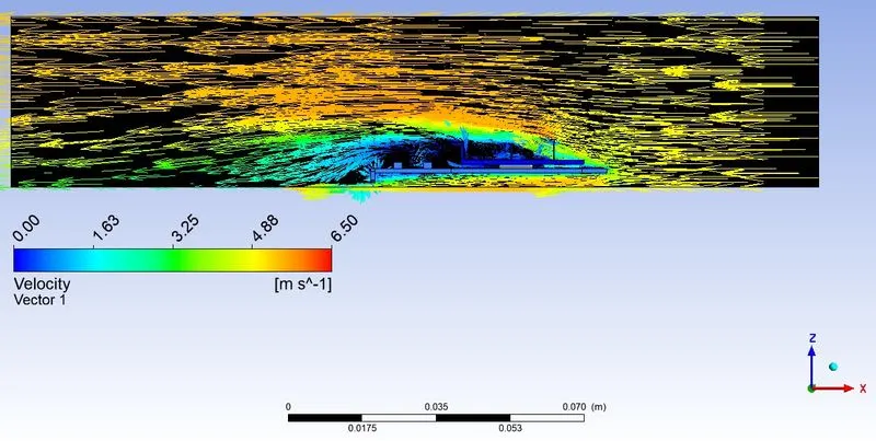
SUMMARY

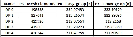
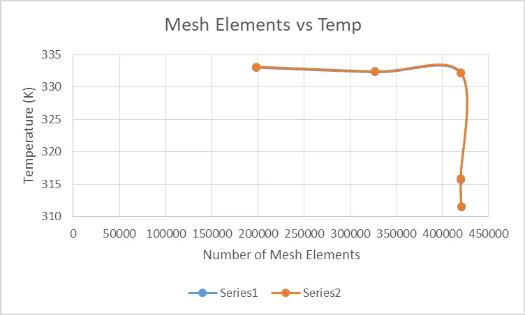
Series 1 - Average Temperature in Kelvin
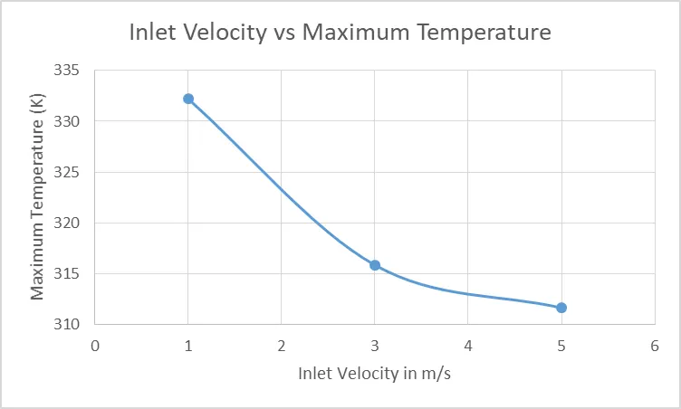
Series 2 - Maximum Temperature in Kelvin

CONCLUSION
- There is no much difference between average temperature and maximum teperature.
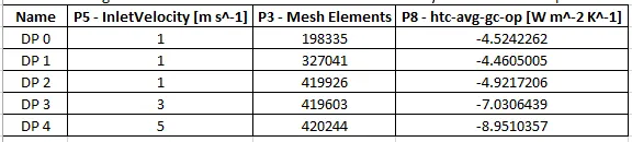
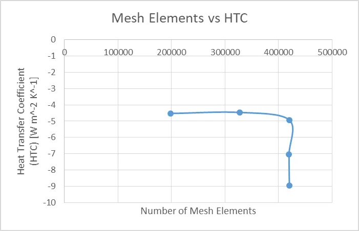
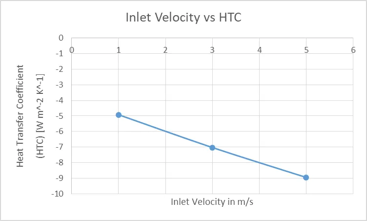
- The change in heat transfer coefficient is negligible if compared with the same inlet velocity.
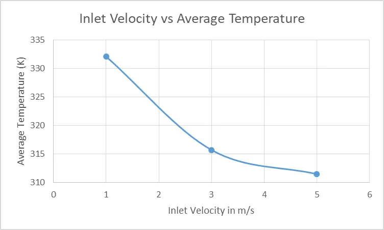
- The change in temperature is negligible if compared with the same inlet velocity.
- Heat transfer coefficient increases with an increase in inlet velocity.
- Average temperature and Maximum temperature decreases with an increase in inlet velocity.